Unit - 3
Potential of charge system, Conductors, Dielectric, Capacitance and Poison’s and Laplace Equations
The electric potential or just potential tells us something about how a charge will move in a given situation. For example, the electric potential due to a point charge of magnitude Q is
V(r) = kQ/r
The electric potential will be positive or negative depending on the sign of the charge Q. If Q is positive, V will also be positive. If Q is negative, V will be negative. The potential is a scalar -- not a vector. So there is no direction associated with that minus sign. The minus sign tells you what the charge is. This also makes it easier to manipulate this quantity than a vector quantity. If Q is positive, it will repel other positive charges. The strength of that repulsion is proportional to 1/r. The unit of potential is called the Volt:
V(r) = kQ/r = Nm/C = J/C= Volts
The potential difference.
In most cases, we are most concerned with differences in potential energy – not the absolute potential energy. We define the potential difference to be the difference in potential energy of a charge at two different points. For example, if I have a charge, q, that is between two charged plates, its motion will depend on how far it is from each plate. If we compare two positions, A and B, we say that VAB is the potential difference between points A and B
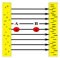
The unit of potential difference is the volt and was named in honor of Alessandro Volta, who discovered the battery. The potential is generally measured with respect to ground.
Key takeaway
Potential Difference | Electromotive Force [EMF] |
Work done by electric force (Fe) on unit positive charge to move it through a distance l in the direction of electric field id called potential difference | EMF is defined as the work done by the force to move unit positive charge from negative to positive terminal of battery. |
P.D = v=w/q=Fel/q | EMF= W/q= Fed/q |
S.I unit is volts | Si Unit is volts |
Potential difference is effect | EMF is a cause |
It depends upon resistance of circuit | It does not depend upon the resistance |
It is always less than emf | It is greater than potential difference |
It does not remain constant | It remains constant |
Potential difference takes place between two points | EMF creates potential difference in entire circuit. |
We have seen so far the charge distributions have been discrete i.e. made up of individual point particles.
If a charge distribution is continuous rather than discrete, we can generalize the definition of the electric field. We simply divide the charge into infinitesimal pieces and treat each piece as a point charge.
We know that charge is quantized so there is no such thing as a truly continuous charge distribution. However, in most practical cases, the total charge creating the field involves such a huge number of discrete charges.
For simplicity we can safely ignore the discrete nature of the charge and consider it to be continuous. This is exactly the kind of approximation we make when we deal with a bucket of water as a continuous fluid rather than a collection of H2O molecules.
Continuous charge distribution: an arrangement of many discrete charges so closely spaced that the charge is treated as a continuum, resulting in a replacement of discrete sums with integrals.
Distribution of charges
(a) Line charge density
(b) Surface charge density
(c) Volume charge density
(d) Some of the components of the total electric field cancel out, with the remainder resulting in a net electric field
Definitions of charge density:
(a) λ - Line charge: charge per unit length (linear charge density); units are coulombs per meter (C/m)
(b)  - Surface charge density: Charge per unit area; units are coulombs per square meter (C/m2)
(c)  - Volume charge density: Charge per unit volume; units are coulombs per cubic meter (C/m3)
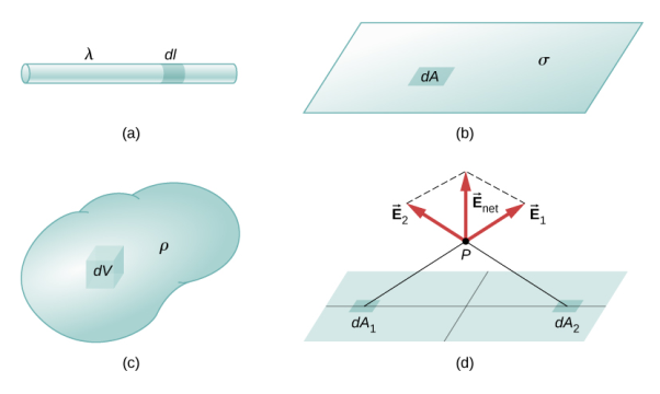
Figure 1: Charge Distribution
Some of the important result for electric field due to point charge, line charge density, surface charge density and volume charge density.
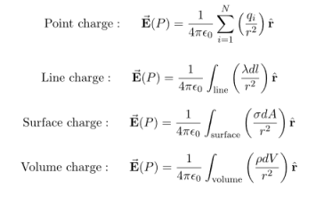
Note carefully the meaning of r in these equations: It is the distance from the charge element λdl,  ,
,  to the location of interest, P(x,y,z) (the point in space where you want to determine the field). However, don’t confuse this with the meaning of
  .
.
If the charge distribution is continuous, the potential at a point P can be found by summing over the contributions from individual differential elements of charge. Dq
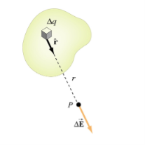
Figure 2: Continuous charge distribution
Consider the charge distribution shown in Figure. Taking infinity as our reference point with zero potential, the electric potential at P due to dq is

Summing over contributions from all differential elements, we have

We established the relation between  and V. If we consider two points which are separated by a small distance
  , the following differential form is obtained.
DV = -
In Cartesian coordinates,
E = Ex  + Ey
+ Ey + Ez
+ Ez
And  = dx
= dx  + dy
+ dy + dz
+ dz
DV = ( Ex  + Ey
+ Ey + Ez
+ Ez ) .( dx
  + dy
+ dy + dz
+ dz )
)
DV = ( Ex dx+ Eydy + Ezdz
This implies
Ex =  Ey =
Ey =  Ez =
Ez = 
By introducing a differential quantity called the “del (gradient) operator”

The electric field can be written as

 =-
=- 
Notice that ∇ operates on a scalar quantity (electric potential) and results in a vector quantity (electric field). Mathematically, we can think of  as the negative of the gradient of the electric potential V. Physically, the negative sign implies that if V increases as a positive charge moves along some direction, say x, with , then there is a non-vanishing component of
  in the opposite direction(-Ex
  )
)
In the case of gravity, if the gravitational potential increases when a mass is lifted a distance h, the gravitational force must be downward.
If the charge distribution possesses spherical symmetry, then the resulting electric field is a function of the radial distance r, i.e.  = Er
= Er 
In this case, .dV=- Er dr.
If V(r) is known, then  may be obtained as

For example, the electric potential due to a point charge q is
V = 

Using the above formula, the electric field is simply
E = 

LAWS IN ELECTROSTATICS
There are some important laws we used in electrostatics.
Coulomb’s Law:
The magnitude of the electric force that a particle exerts on another particle is directly proportional to the product of their charges and inversely proportional to the square of the distance between them. The direction of the force is along the line joining the particles.
Mathematically, the electric force F that a particle of charge q’ exerts on a particle of charge q at a distance r is given by the formula
F =k

Where k is a constant of proportionality. This formula not only gives the magnitude of the force, but also the direction, if we interpret a positive value of the force F as repulsive and a negative value as attractive.
When a small positive test charge is brought near a large positive charge, it experiences a force directed away from the large charge. If the test charge is far from the large charge, the electrostatic force given by Coulomb's law is smaller than when it is near. This data of direction and magnitude of an electrostatic force, due to a fixed charge or set of fixed charges, constitutes an electrostatic field. The electric field is defined as the force per unit charge exerted on a small positive test charge (q 0) placed at that point. Mathematically,
E = 
Note that both the force and electric field are vector quantities.
Figure 3: is a pictorial representation of the electric fields surrounding a positive charge and a negative charge. These lines are called field lines or lines of force.
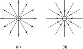
Figure 3: Electric field lines of (a) positive and (b) negative point charges.
Figure 4 shows the electric fields for opposite charges, similar charges, and oppositely charged plates.
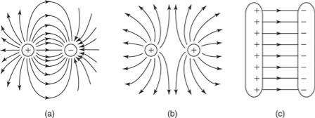
Figure 4: Electric field lines of (a) two opposite charges, (b) two like charges, and (c) two oppositely charged plates.
Electric flux
Electric flux is defined as the number of field lines that pass through a given surface. In Figure , lines of electric flux emerging from a point charge pass through an imaginary spherical surface with the charge at its center.
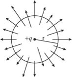
Figure 5: Electric flux
Gauss’s law of electrostatics
It states that the electric flux through any closed surface is proportional to the total electric charge enclosed by this surface.
Φ=q/ϵ0
Gauss’s law for magnetism
Gauss’s law for magnetism states that no magnetic monopoles exists and that the total flux through a closed surface must be zero.
Net flux = ∫ B • dA = 0
Faraday’s law
Faraday’s law states that a current will be induced in a conductor which is exposed to a changing magnetic field
Key Takeaways
- Coulomb’s Law states that the magnitude of the electric force that a particle exerts on another particle is directly proportional to the product of their charges and inversely proportional to the square of the distance between them. The direction of the force is along the line joining the particles.
- Electric flux is defined as the number of field lines that pass through a given surface.
- Gauss’s law of electrostatics states that the electric flux through any closed surface is proportional to the total electric charge enclosed by this surface.
ELECTRIC FIELD DUE TO A DIPOLE
Case (i) Electric field due to an electric dipole at points on the axial line
Consider an electric dipole placed on the x-axis as shown in Figure 6. A point C is located at a distance of r from the midpoint O of the dipole along the axial line.
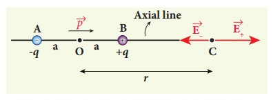
Figure 6: Electric field of the dipole on the axial line
The electric field at a point C due to +q is
 ………(1)
Since the electric dipole moment vector  is from –q to +q and is directed along BC, the above equation is rewritten as
 ………(2)
Where p ^ is the electric dipole moment unit vector from –q to +q.
The electric field at a point C due to –q is
 ………(3)
Since +q is located closer to the point C than –q,  , is stronger than
  , Therefore, the length of the
  vector is drawn larger than that of
  vector.
The total electric field at point C is calculated using the superposition principle of the electric field.
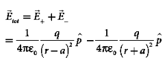 ………(4)
 ………(5)
 ………(6)
Note that the total electric field is along  , since +q is closer to C than –q.
The direction of  , is shown in Figure 7.
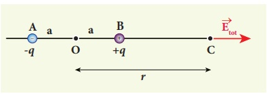
Figure 7: Total electric field of the dipole on the axial line
If the point C is very far away from the dipole then (r >> a). Under this limit the term ( r2 − a2 )2 ≈ r4 . Substituting this into equation (6), we get
 ………(7)
If the point C is chosen on the left side of the dipole, the total electric field is still in the direction of  .
.
Case (ii) Electric field due to an electric dipole at a point on the equatorial plane
Consider a point C at a distance r from the midpoint O of the dipole on the equatorial plane as shown in Figure 8 .
Since the point C is equidistant from +q and –q, the magnitude of the electric fields of +q and –q are the same. The direction of  is along BC and the direction of
  is along CA.
  and
and  are resolved into two components; one component parallel to the dipole axis and the other perpendicular to it. The perpendicular components |
 | sinθ and |
 | sinθ are oppositely directed and cancel each other. The magnitude of the total electric field at point C is the sum of the parallel components of
  + and
+ and  and its direction is along -
 as shown in the Figure 8.
 ………(8)
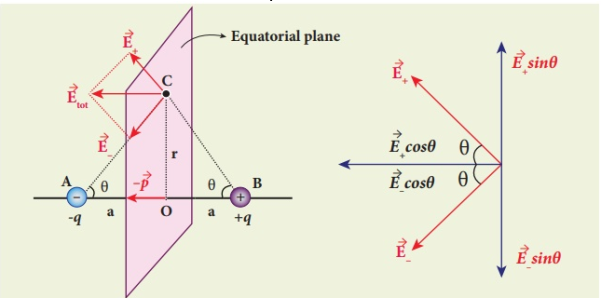
Figure 8: Electric field of the dipole at a point on the equatorial plane
The magnitudes  + and
+ and  are the same and are given by
 ………(9)
By substituting equation (9) into equation (8), we get
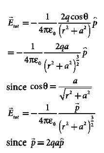 ………(10)
At very large distances (r>>a), the equation (10) becomes
 ………(11)
Important inferences
(i) From equations (7) and (11), it is inferred that for very large distances, the magnitude of the electric field at points on the dipole axis is twice the magnitude of the electric field at points on the equatorial plane. The direction of the electric field at points on the dipole axis is directed along the direction of dipole moment vector  but at points on the equatorial plane it is directed opposite to the dipole moment vector, that is along -
 .
.
(ii) At very large distances, the electric field due to a dipole varies as 1/r3. Note that for a point charge, the electric field varies as 1/r2. This implies that the electric field due to a dipole at very large distances goes to zero faster than the electric field due to a point charge. The reason for this behaviour is that at very large distance, the two charges appear to be close to each other and neutralize each other.
 (iii) The equations (7) and (11) are valid only at very large distances (r>>a). Suppose the distance 2a approaches zero and q approaches infinity such that the product of 2aq = p is finite, then the dipole is called a point dipole. For such point dipoles, equations (7) and (11) are exact and hold true for any r.
Key takeaway
- Electric field due to an electric dipole at points on the axial line is given as
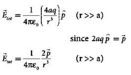
- Electric field due to an electric dipole at a point on the equatorial plane At very large distances (r>>a) given as

Problem:
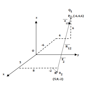
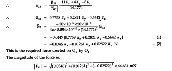
A charge Q1=-20µC is located at P(-6,4,6) and a charge Q2=50µC is located at R(5,8,-2) in a free space . Find the force exerted on Q2 by Q1 in vector form. The distances given are in meters.
From the co-ordinates of P and R the respective position vectors are :

And


Potential Gradient
Consider that in space let W be the unique function of x,y,z co-ordinates in the cartesian system. This is scalar function denoted as W(x,y,z) . Consider the vector operator in cartesian system denoted as  called del. It is defined as


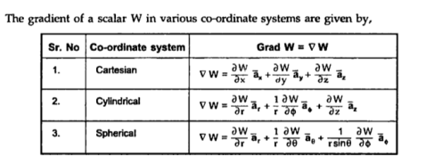
Properties:
The various properties of a gradient of a scalar field W are:
- The gradient
 W gives the maximum rate of change of W per unit distance
 - The gradient
 W always indicates the direction of the maximum rate of ch W.
 - The gradient
 W at any point is perpendicular to the constant W surface passes through the point.
 - The directional derivative of W along the unit vector
 ( dot product which is the projection of
  W always indicates the direction of maximum rate of ch W.


Problem:
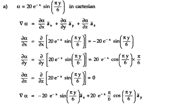
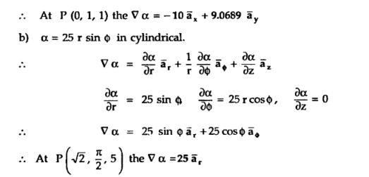
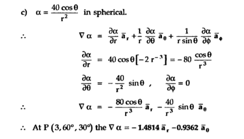
A scalar field is given by


A conductor has an abundance of charge that is free to move. Let us consider an example, in the figure below. When an external Electric Field Ee is applied, the positive free charges are pushed along the same direction as that of the field and the negative free charges move in the opposite direction. This charge migration takes place very quickly. The free charges first accumulate on the surface of the conductor and form an induced surface charge. Then the induced charges set up an induced internal Electric Field Ei, which cancels the externally applied Electric field Ee. This leads to an important property of a conductor:
A perfect conductor ( ) cannot contain an electrostatic field within it.
A conductor is called an equipotential body which means that potential is same everywhere in the conductor. This is because E = - = 0.
= 0.
Under static conditions,
E=0,  = 0, Vab = 0 inside a conductor.
Where Vab is the potential difference between points a and b in the conductor.
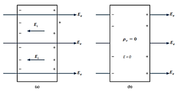
Figure 9: (a) An isolated conductor under the influence of an applied field. (b) A conductor has zero electric field under static conditions.
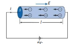
Figure 10: A cylindrical conductor at Potential V
We now consider a conductor whose ends are maintained at a potential difference V, as shown in Figure 5. In this case, E  0 inside the conductor. Since there is no static equilibrium in Figure 5 and the conductor is not isolated but is wired to a source of electromotive force, which compels the free charges to move and prevents the eventual establishment of electrostatic equilibrium. Thus, in this case an electric field must exist inside the conductor to sustain the flow of current.
As the electrons move, they encounter some damping forces called resistance. Based on Ohm's law the resistance of the conducting material is determined.
We assume the conductor has a uniform cross section of area A and is of length l. The direction of the electric field E produced is the same as the direction of the flow of positive charges or current I. This direction is opposite to the direction of the flow of electrons. The electric field applied is uniform and its magnitude is given by:
E =  ….(1)
….(1)
Since the conductor has a uniform cross section,
 ….(2)
….(2)
 ……(3)
……(3)
Hence,  ………(4)
 ……(5)
……(5)
Where  , the resistivity of the conductor. Eq. 5 is used in determining the resistance of the conductor when area of cross-section is uniform.
Definitions:
A dielectric is an electrical insulator that can be polarized by an applied electric field. Or
A dielectric is non-conducting material which stores electrical charges.
In other words, A material that does not conduct electricity but on applying electric field, induced charges produced on its faces. Such an insulator is called Dielectric.
Dielectrics are insulators i.e. non-conducting substances which are bad conductor of electric current. Dielectric materials can stores an electrostatic charge while dissipating minimal energy in the form of heat.
Examples of dielectric are Mica, Plastics, Glass, Porcelain and Various Metal Oxides and even dry air is also example of dielectric. The dielectric constant of a vacuum is, of course, unity.
Classification of Dielectric
The response of a dielectric material depends on the nature of its molecules. The molecules of a dielectric is of two types
- Polar molecules
- Non polar molecules
Polar Molecules: Polar Molecules are those in which centre of gravity of positive and negative charge does not coincide with each other. This is because they all are asymmetric in shape. Examples: H2O, CO2, NO2 etc. The molecule of material are composed of two or more different atoms, which have permanently dipole moment because the centre of gravity of positive charge and negative charge does not coincide with each other but separated by a finite (small) distance.
Normally this type of molecular dipole in polar dielectric are randomly oriented such that their net dipole moment becomes zero and material act as a neutral material.
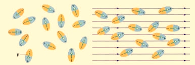
Figure 11: Effect of electric felid on dielectric
Polar Molecules are those type of dielectric in which the possibilities that the positive and negative molecules will coincide with each other is null or zero.
Non-Polar Molecule: Non-polar molecules are those in which centre of gravity of positive charge and negative charge coincide with each other. The molecule has zero dipole moment as they all are symmetric in shape. Examples: O2, N2, H2 etc.
Dielectrics materials in which the molecule's center of gravity of positive charge and negative charge coincide with each other and so the molecules are electrically neutral and hence zero dipole moment.
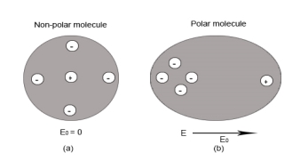
Figure 12: Polar molecules & Non polar molecules
Difference between Dielectric and Insulators
Dielectrics are often confused with insulators. Here are some points of differences
- Dielectric is the material which stores the electrical energy in an electric field whereas insulator is that material which blocks the flow of electrons.
- Dielectric material is polarised whereas insulator material doesn’t get polarised.
- Molecules in dielectric are weakly bounded as compared to molecules in insulator.
- Dielectric material has high dielectric constant whereas insulator has low dielectric constant.
- Examples of Dielectric material are dry air, vacuum, Glass, Porcelain, Various Metal Oxides and distilled water. Whereas Examples of insulator are cotton, plastic, rubber etc.
In dielectric material molecules are tightly bounded to the nucleus and not able to move freely as in case of conductor. But when a dielectric material is placed in an electric field, electric charges do not flow through the material as they flow in case of an electrical conductor but only slightly shift from their average equilibrium positions causing dielectric polarization. Because of dielectric polarization, positive charges are displaced in the direction of the field and negative charges shift in the direction opposite to the field. In dielectric molecules are tightly bound to the nucleus and not able to move freely as in case of conductors. The dielectric material is largely used in the manufacturing of capacitor.
Response of Dielectric to External Electric Field
In case of Polar Molecules -When the electric field is not present, it causes the electric dipole moment of these molecules in a random direction. This is why the average dipole moment is zero. If the external electric field is present, the molecules align themselves in the direction electric field and resulted in having dipole moment.
In case of Non-Polar Molecules – As we know nonpolar molecule has zero dipole moment. In spite of zero dipole, when a dielectric nonpolar material is placed in an electric field. The positive and the negative charges in a nonpolar molecule experience forces in opposite directions. This force causes the separation between the charges and hence nonpolar molecule experiences induced dipole moment.
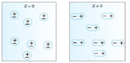
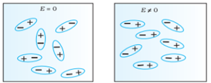
Figure 13 (a) (left) Non Polar Molecule (b) (right) Polar Molecule
Key Takeaways
- A dielectric is non-conducting material which stores electrical charges.
- Examples of dielectric are Mica, Plastics, Glass, Porcelain and Various Metal Oxides and even dry air is also example of dielectric.
- The molecules of a dielectric is of two types Polar molecules and Non-polar molecules
- Polar Molecules are those in which centre of gravity of positive and negative charge does not coincide with each other.
- Non-polar molecules are those in which centre of gravity of positive charge and negative charge coincide with each other. The molecule has zero dipole moment as they all are symmetric in shape.
- In the presence of electric field molecules gets polarized.
When electric field passes from one medium to the other it is necessary to study the conditions at the boundary between two media. The conditions existing at the boundary of two media when field passes from one medium to the other are called boundary conditions.
Depending on the nature of the media there are two situations of boundary conditions:
- Boundary between conductor and free space
- Boundary between two dielectrics with different properties
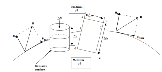
Fig 14. The boundary between conductor and free space.
Consider a boundary between conductor and free space. The conductor has infinite conductivity. For ideal conductor
The field intensity inside the conductor is zero and flux density inside a conductor is zero.
No charge can exist within a conductor. The charge appears on the surface in the form of surface charge density.
The charge density within the conductor is zero.
Thus  within the conductor is zero
  is the surface charge density.
In order to determine the boundary conditions, use the closed path and Gaussian surface.
 at the boundary.
Let  be the electric field intensity in the direction making some angle with the boundary. This
  is resolved into two components
The component tangential to the surface
The component normal to the surface.

The integral of  carried over a closed contour is zero that is the work done in carrying unit positive charge along the closed path is zero.
Consider a rectangular closed path abcda as shown in figure. It is traced in clockwise direction hence  is divided into four parts:

The closed contour is placed in such a way that its two sides a-b and c-d are parallel to tangential direction to the surface while the other two are normal to the surface at the boundary.
The rectangle with height  and width
  is placed in a manner that half of it is conductor and remaining half is free space. Thus
  is in the conductor and
  in free space.
The portion of c-d in conductor where  hence the corresponding integral is zero.

The width  therefore E is constant hence,

But  is tangential to the boundary hence

Now b-c is parallel to the normal component therefore  along this direction. Let

For small height  EN is assumed constant and taken out of integration.

But out of b-c , b-2 is in free space and 2-c is in the conductor when 

For path d-a the condition is same as for b-c only direction is opposite.

Substituting eq 4 and 8 and 3 and 9 we get

Thus, the tangential component of the electric field intensity is zero at the boundary between conductor and free space.
DN at the boundary
To find the normal component of  select a closed Gaussian surface in the form of right circular cylinder as shown in figure.
  is placed in such a way that
  is in the conductor and
  is in free space. Its axis is normal direction to the surface.
According to Gauss’s law ,

The surface integral must be evaluated over three surfaces top , bottom and lateral.
Let the area of top and bottom be same 

The bottom surface is in conductor where  hence corresponding integral is zero.
The top surface is in free space hence top surface is shifted at the boundary with 

The lateral surface area is 2π r  where r is the radius of the cylinder. But as
  ->0 this area reduces to zero and the integral is zero.
While only component  is normal having magnitude DN the top surface is very small over which DN can be assumed constant and taken out of integration.

From Gauss’s Law

But at the boundary the charge exists in the form of surface charge density  s
s

Equating 16 and 17 we get

Thus the flux leaves the surface normally and the normal component of flux density is equal to surface charge density

Boundary conditions between conductor and dielectric
The free space is dielectric with  . Thus if the boundary is between conductor and dielectric with

Problem:
A potential field is given as V = 100 e -5x sin 3y cos 4z V. Let point P (0.1, ,
,  ) be located at a conductor free space boundary. At point P find the magnitudes of
a) V b)  c) Et d) EN e)
  f) DN g)
At P , x=0.1 , y=  z =
z =  / 24.
/ 24.
V = 100 e – 0.5 sin 3 / 12 cos 4
 / 24 = 37.1422 V
 = -
= -  V =
V = 
= -100[-5 e 5x sin 3y cos 4z  + e -5x (3) (cos3y)(cos 4z)
  + e-5x (sin 3y) (4) (-sin 4z)
At P
 = [-100[-1.857
  = 1.114
  + 85.776
  ]= 185.7
  -111.4
  + 85.776
|E| = 232.9206 V/m
c ) Et = 0 V/m P is on the boundary.
d ) EN = | | = 232.9206 V
e )  = 8.854 x 10 -12 [185.7
  -111.4
  + 85.776
  ]
]
 = 1.992 nC /m2
DN =  = 1.992 nC /m2
 = 1.992 nC / m2
A capacitor is essentially a device consisting of an arrangement of conductors for storing charges. As a consequence, it also stores electrostatic energy. The simplest capacitor consists of two conductors, one carrying a charge Q and the other a charge -Q. Let  1 be the potential of the first conductor and
  2 that of the second. Since the conductor is an equipotential surface, the potential difference between the conductors
  1 -
1 -  2 is also constant, and is given by

Q = C 
A capacitor consisting of a single conductor (like the spherical conductor described above) may be considered to be one part of a conductor pair where the second conductor containing the opposite charge is at infinity.
Parallel Plate Capacitor:
A parallel plate capacitor consists of two parallel metal plates, each of area A separated by a distance d. A potential difference  is maintained between the two plates. If the charge on the positive plate is +Q and that on the negative plate is -Q, the electric field in the region between the two plates is

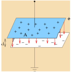
The potential difference between the plates is

The value of capacitance C is

Key takeaway
The capacitance for a parallel plate capacitor is proportional to the surface area and inversely proportional to the separation between its plates.
Consider a long straight cylindrical conductor A of radius r metres. Let the conductor operate at such a potential (VA) that charge QA coulombs per metre exists on the conductor. It is desired to find the expression for VA. The electric intensity E at a distance x from the centre of the conductor in air is given by

As x approaches infinity, the value of E approaches zero. Therefore, the potential difference between conductor A and infinity distant neutral plane is given by:

Consider a single phase overhead transmission line consisting of two parallel conductors A and B spaced d metres apart in air. Suppose that radius of each conductor is r metres. Let their respective charge be + Q and − Q coulombs per metre length.

The total p.d. Between conductor A and neutral infinite plane is
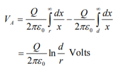
Similarly, p.d. Between conductor B and neutral infinite plane is


Both these potentials are w.r.t. The same neutral plane. Since the unlike charges attract each other, the potential difference between the conductors is
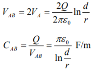
Capacitance to neutral: Above equation gives the capacitance between the conductors of a two wire line. Often it is desired to know the capacitance between one of the conductors and a neutral point between them. Since potential of the mid-point between the conductors is zero, the potential difference between each conductor and the ground or neutral is half the potential difference between the conductors. Thus, the capacitance to ground or capacitance to neutral for the two wire line is twice the line-to-line capacitance.

From the Gauss’s law in the point form Poisson’s equation can be derived. Consider the Gauss’s law in the point form as

It is known that for a homogeneous, isotropic, and linear medium, flux density and electric field intensity are directly proportional. Thus,
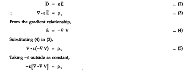

If in a certain region volume change density is zero which is true for dielectric medium then the Poissons equation takes the form

This is special case of Poisson’s equation is called Laplace’s equation. The  operation is called the Laplacian of V
References:
- W.H. Hayt, “Engineering Electromagnetics”, TMH Publication 2006
- N.N.Rao Electromagnetic Engg. V Edition, Prentice Hall. 2005
- Fawwaz T.Ulaby Applied Electromagnetics, Prentice Hall. 1999
- Krauss Electromagnetic Engg. IV Edition, Tata Mc Graw Hill. 2003
- Shevgaonkar Electromagnetic Waves,T ata Mc Graw Hill 2002