Unit - 4
The steady Magnetic Field and Magnetic forces
Let us consider a conductor carrying direct current I and a steady magnetic field is produced around it. The law helps us to obtain magnetic field intensity  produced at a point P due to differential current element idL. The current carrying conductor is as shown in the figure.
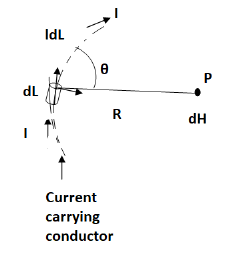
Consider differential length dL and differential current IdL. This is a small part of the current carrying conductor. The point P is at a distance R from differential current element.  is the angle between the differential current element and the line joining point P to the differential current element?
Bio-Savart Law states that the magnetic field intensity  produced at point P due to differential current IdL is,
Proportional to the product of current I and differential length dL.
The sine of angle between the element and the line joining point P to the element.
Inversely proportional to the square of distance R between point P and the element.
Bio-Savart law can be stated as,
d α I dL sin Ɵ / R 2
d =k I dL sin Ɵ / R 2
Where k = constant of proportionality
In SI units, k = 1/ 4 π.
d = I dL sin Ɵ / 4πR 2
In vector form,
Let dL = Magnitude of vector length  and
and
 R = Unit vector in the direction from differential current element to point P.
Then from rule of cross product,
 x
x  R = dL |
 R| sin Ɵ = dL sin Ɵ |
 R|=1
R|=1
Replacing we get
d = I d
= I d  x
x  R / 4πR 2 A/m
 R =
R =  / |
/ | =
=  / R
/ R
d = I d
= I d  x
x  / 4πR 3 A/m
This is the mathematical form of Bio-Savarts Law.
According to direction of cross product the direction of  is normal to the plane containing two vectors and the normal direction along the progress of right- handed screw turned from
  through smaller angle
  towards the line joining element to point P.
Therefore, direction of  is normal to the plane of paper.
According to right- handed screw rule the direction of  is going into the plane of paper.
The entire conductor is made of differential elements. Therefore, in order to obtain the total magnetic field take the integral
 =
=  d
d  x
x  R / 4πR 2
The closed line integral is required to ensure that all the current elements are considered because current can flow only in the closed path provided by close circuit.
If the current element is considered at point 1 and point P at point 2 as shown in the figure, then
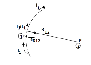
D  2 = I1 d
  1 x x
1 x x  R 12 / 4πR 2 12
Where
I1 = current flowing through dL1 at point 1.
DL1 = Differential vector length at point 1
 R12 = Unit vector in the direction from element at point 1 to point P at point2.
 R12 =
R12 =  / |
/ | | =
| =  / R12
/ R12
 =
=  d
d  x
x  R12 / 4 π R 2 12 A/m
This integral form is called Biot-Savart law.
Problem:
Find the incremental field strength at P2 due to the current element of 2πa2 Am at P1. The co-ordinates of P1 and P2 are (4,0,0) and (0,3,0) respectively.
Solution:
The two points P1 and P2 along with the I1dL1 current element at I1 are shown in figure.
According to Bio-Savart law
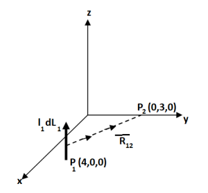
d  = I1 d
  x
x  R12 / 4 π R 2 12
 = (0-4)
  + (3-0) ay + 0. Az
 R12 =
R12 =  12 /|
12 /|  12 |
12 |
= -4  x + 3
x + 3  y /
y /  16 + 9
= -4  x + 3
x + 3  y /5
y /5
While I1 dL1 = 2
 A m.
A m.

Gauss’s Law is useful to obtain  in case of complex problems. I magnetostatics complex problems can be solved using Ampere’s Law.
It states that
The line integral of magnetic field intensity  around closed path is exactly equal to direct current enclosed by that path.
The mathematical representation of Ampere’s circuital law is
 ---------------------(1)
This law is useful to determine  when current distribution is symmetrical.
Proof:

Consider a long straight conductor carrying direct current I placed along z axis as shown in figure. Consider a closed circular path of radius r which encloses the straight conductor carrying direct current I. The point P is at perpendicular distance r from the conductor.
Consider  at point P which is direction
  direction tangential to circular path at point P.
Therefore,

While  obtained at point P, from Biot-Savart law due to infinitely long conductor is,
 = 1/ 2 π r .
  ɸ . r dɸ .
  ɸ
ɸ
= 1/ 2  r . dɸ = 1/ 2 π . dɸ
Integrating  .
.  over the entire closed path
 .
.  =
=  dɸ = 1/ 2 π [ɸ] 0 2π = I. 2 π/ 2 π
This proves that the integral  .
.  along closed path gives the direct current enclosed by that closed path.
Steps to Apply Amper’s Circuital Law:
Step1: Consider a closed path preferably symmetrical such that it encloses the direct current I once. This is Amperian path.
Step2: Consider differential length  depending upon the co-ordinate system used.
Step3: Identify the symmetry and find in which direction  exists according to co-ordinate system used.
Step 4: Find  .
.  . Make sure that
  and
and  are in the same direction.
Step 5: Find the integral of  .
.  around the closed path. And equate it to current I enclosed by the path.
To apply Ampere’s circuital law the following conditions must be satisfied,
- The
 ie either tangential or normal to the path, at each point of the closed path.
 - The magnitude of
 must be same at all points of the path where
  is tangential.
 due to straight conductors
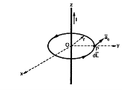
Consider an infinitely long straight conductor which is placed along z-axis carrying direct current I as shown in figure. Consider the Amperian closed path enclosing the conductor as shown in figure. Consider point P on the closed path at which  is obtained. The radius of the path is r from the conductor. The magnitude of
  depends on r and the direction is always tangential to the closed path. So,
  has only component in
 direction say H
  .
.
Consider elementary length  at point P in cylindrical co-ordinates it is r d
 in
in 
 = Hɸ
= Hɸ  ɸ and
ɸ and  = r dɸ .
 ɸ
ɸ
 .
.  = Hɸ
= Hɸ  ɸ . r dɸ .
 ɸ = Hɸ r dɸ
According to Ampere’s circuit law,
 = I
= I
 ɸ . r. dɸ = I
Hɸ . r  . dɸ = I
Hɸ . r [2π] =I
Hɸ = 1/ 2π r
Hence  at point P is given by
 = Hɸ.
= Hɸ.  ɸ = 1/ 2 π r.
  ɸ
ɸ
The theorem permits transformation of certain integral calculated over the surface into line integral stated as.
The line integral of the tangential component of a vector around closed path L is equal to the surface integral of the normal component of curl
  over the
  enclosed by the path L.
In symbol the statement of theorem becomes

Here we have a vector function of position is vector element of distance around the boundary, and is the normal to the surface chosen to point up if the position direction of transporting the boundary is chosen,
Proof:
Let’s divide the surface S into a set of small approximately rectangular area as shown in figure. The theory will first be proved for the separate rectangular area and den by combining the result.
Latest choose the the X and Y axis two point along the sides of the rectangle, z axis along the normal n as shown in figure 3.3 of the coordinates of point A are (x,y) the coordinates of B,C and D will be x+dx, y, x+dx, y+dy, x,y+dy respectively as shown in figure 3.4. Thus the elemental area of rectangle ABCD will be

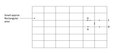
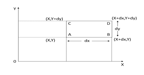
Figure. Proof of stokes theorem
Curl  that is
 is given by

Therefore

Now,  will be length be AB+ BC-CD-DA (negative sign is due to direction along the length)
Therefore


If we go around so always to keep surface on the left
Substituting the value of
From equation 2 we get

Hence the theorem is proved.
In free space
In free space, magnetic flux density B is defined as:
 Webers/m2 or Tesla (T).
 (henry/meters)
μ is the permeability of free space.
The total magnetic flux through a surface is given by

Applying the definition of the divergence,

Therefore, the lines H or B are closed lines (E or D are open lines).
Conductor
For the magnetic flux between the conductors of a coaxial line of length d, the magnetic flux density is given by

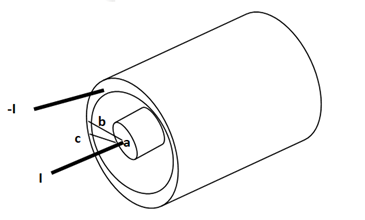
The magnetic flux contained between the conductors in a length d is the flux crossing any radial plane extending from  = a and
  = b and from z=0 and z=d.


Problem: A radial field  = 2.39 x 10 6 / r cos
  A/m exists in free space. Find the magnetic flux crossing the surface defined by 0 ≤
 ≤ π/4 and 0 ≤ z ≤ 1m.
Solution:
The portion of the cylinder is shown in figure. The flux crossing the given surface is given by
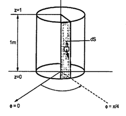

 normal to
  direction is,


Problem: Find the flux passing the portion of the plane  = π / 4 defined by 0.01 < r < 0.05m and 0<z<2 m. A current filament of 2.5 A is along z-axis in the
  direction in free surface.
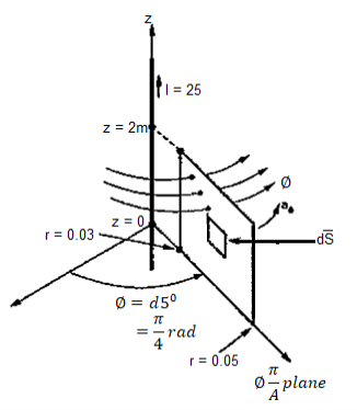
Due to current carrying conductor in free space along z-axis

 A/m
A/m


The flux crossing the surface is given by


 normal to
  direction


If Vm is the scalar magnetic potential, then it must satisfy the equation
 x
x  Vm =0
Vm =0
But the scalar magnetic potential is related to the magnetic field intensity  as
as
 = -
= -  Vm
Vm
 x (-
x (-  =0 that is
  x (
x (  =0
=0
 x (
x (  =
=  that is
  =0
=0
Thus scalar magnetic potential Vm can be defined for source free region where  that is the current density is zero.
 = -
= -  Vm only for
  =0
=0
Vector magnetic potential:
The vector magnetic potential is denoted as  and measured in Wb/m . It has to satisfy equation that divergence of a curl of a vector is always zero.
 .
.  =0
=0
 .
.  =0
=0
 =
= 

The curl of a vector magnetic potential is the flux density.
Now  .
.  =
= 

 /
/  =
= 
 =
= 


 =
= 

 x
x  x A = =

Using vector identity to express on L.H.S we write

 = =
= =  J
J
J = 1/  [
[ 
 ] = 1/ 1/
  [
[  x
x  ) -
) -  2
2  ]
]
Thus if vector magnetic potential is known then current density J can be obtained.
Solved Examples
Q1. The plane of a circular coil is horizontal. It has 10 turns each of 8 cm radius. A current of 2 A flows through it, which appears clock wise from a point vertically above it. Find the magnitude and direction of the magnetic field at the centre of the coil due to current.
Sol. Here, n=10, I=2A
r= 8cm = 0.08 m
Magnitude of magnetic field induction at the centre of the circular coil carrying current is


Q2. A long straight solid metal road of radius 4 cm carries a current 2A uniformly distributed over its circular cross section. Find the magnetic field induction of a distance 3 cm from the axis of wire.
Sol. The point P is lying inside the rod at perpendicular distance (r=3cm) from the axis of wire. Draw a circular closed path of radius r with centre on axis of rod such that the point P lies on this closed path.
Current enclosed by closed path

The magnetic field produced due to current flowing in the rod at every point over the closed path is tangential to it and is equal in magnitude at all points of path.
Line integral of  over closed path is


Or,


Q3. Determine the magnetic flux density B distance d meter from infinite straight wire carrying current I.
Sol. Let P be the point where B is to be evaluated consider an element it yr=dl of infinite wire shown in figure 1 tattoo distance r from point P.
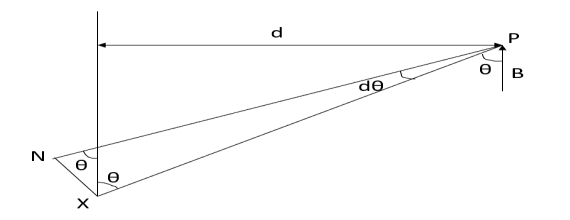
Figure: An infinite wire carrying a current I
Magnetic field B at P due to element dl from equation is given by

We see that
 d
d
Therefore, 


Substituting their values in above expression we have


Q4. Compute curl A if .
.
Sol. Given that


Partial derivatives will be


Putting these values of partial derivations in in equation


Q5. Verify that the vector field is both irrational (π has zero curl) and
Solenoid (π has zero divergence)
Sol. (i) given that

The partial derivatives will be


Putting these values of partial derivatives in curl equation


Hence the given field A is irrational since its curl zero
(ii) substituting the above calculated value of partial derivatives


Hence the given field is solenoid since divergence is zero.
Q6. Find the work done by the force vector  .
.
Around the closed path as shown in figure.
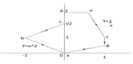
Sol. The total work done by the force vector is

The integrals consists of 7 parts which can be calculated separately


This problem can be solved by Stokes theorem.
According two stokes theorem, the work done by force vector is
 where S is surface bounded by the closed path and F is the given force vector for this force vector the curl is equal to
Choose normal vector


Q7. Find the curl of magnetic field and show that it is proportional to the current density.
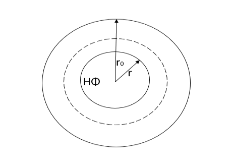
Figure. Cross section of cylindrical conductor
Sol. For the cylindrical coordinates

But is entirely in the Q directions

The variation of is along r axis


Which is proportional to J.
Q8. Calculate the magnetic flux density due to coil 100 ampere turn and area of  on the axis of coil at a distance 10 metre from the centre and at a point distance 10 metres in a direction at right angle to axis.
Sol. B on the axis of the coil


(ii) B ad perpendicular to axis
B at any point ( ) is given by


M- Magnetic moment of a current loop and is equal to 

When


Putting the given values we have


Q9. Circuit carrying a current of I ampere from a regular polygon of n side inscribed in circumscribing circle of radius R. Calculate the magnetic flux density at the centre of the polygon and show that for a circular loop if n tends to infinity.
Sol. Since the given regular polygon has n sides


P is perpendicular chopped from centre to the sides AB and OAB is an equilateral triangle.


B due to AB is given by


 due to regular polygon of n sides will be

When n tends to


 at the centre of the circular loop of radius R.
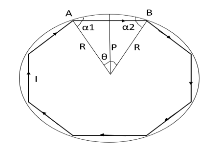
Figure: Regular polygon inscribed in a circle of radius R.
The emf of a moving point charge is


When calculating the derivatives the retarded time depends on r and t. This complicates algebra significantly.
For instance

Where
 is the acceleration of particle in retarded time.


The magnetic field of a point charge is always perpendicular to the electric field and to the vector from the retarded point.
Both fields depend both on velocity and acceleration of a moving charge!
Ampere law state that the force  betweentwo parallel wires carrying
  is proportional to

Where r is the distance between the centres of the wire.
The force is attractive if the currents are in the same direction and is repulsive if they are opposite in direction. Equation (1) can be rewritten as

Where K is proportionality constant
K=
 Is absolute permeability of the medium and its unit is henxy per met x

Is permeability of free space that is vacuum and is equal to  henxy/metre and
  is relative permeability
Substituting the value of K we have

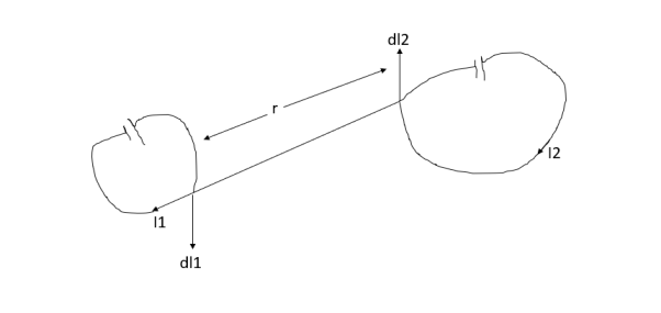
Figure: Force between the pair of current 
In general case of a pair of currents as shown in figure the force which one current exert on the other. When both are in free space is given by a more complex expression. But it is proportional to 

Where  is force exerted on currents
  by current
 and the integrals are evaluated over the two wires. The vector
  point in the direction of the positive current flow,
 is the unit vector pointing from
  and r is the distance between the two elements
  .
.
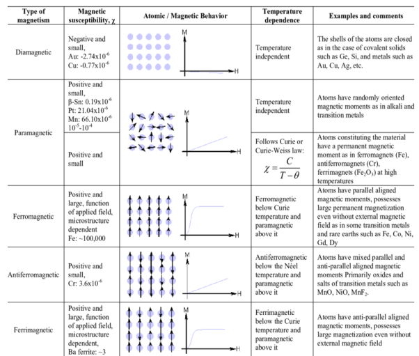
A material is magnetically characterized based on the way it can be magnetized. This depends on the material’s magnetic susceptibility – its magnitude and sign.
Three basic magnetisms are:
- Dia-magnetism
- Para-magnetism
- Ferro-magnetism.
- Anti-ferro-magnetism and ferri-magnetisms are considered as subclasses of ferro-magnetism.
Dia-magnetism
- Very weak; exists ONLY in presence of an external field, non-permanent.
- Applied external field acts on atoms of a material, slightly unbalancing their orbiting electrons, and creates small magnetic dipoles within atoms which oppose the applied field. This action produces a negative magnetic effect known as diamagnetism.
- The induced magnetic moment is small, and the magnetization (M) direction is opposite to the direction of applied field (H).
- Thus, the relative permeability is less than unity i.e. magnetic susceptibility is negative, and is in order of -10-5.
- Materials such as Cu, Ag, Si, Ag and alumina are diamagnetic at room temperature.
Para-magnetism
- Slightly stronger; when an external field is applied dipoles line-up with the field, resulting in a positive magnetization. However, the dipoles do not interact.
- Materials which exhibit a small positive magnetic susceptibility in the presence of a magnetic field are called para-magnetic, and the effect is termed as para-magnetism.
- In the absence of an external field, the orientations of atomic magnetic moments are random leading to no net magnetization.
- When an external field is applied dipoles line-up with the field, resulting in a positive magnetization.
- However, because the dipoles do not interact, extremely large magnetic fields are required to align all of the dipoles.
- In addition, the effect is lost as soon as the magnetic field is removed.
- Since thermal agitation randomizes the directions of the magnetic dipoles, an increase in temperature decreases the paramagnetic effect.
- Para-magnetism is produced in many materials like aluminium, calcium, titanium, alloys of copper. Magnetic susceptibility of these materials is slightly positive, and lies in the range +10-5 to +10-2.
Ferro-magnetism
- Both dia- and para- magnetic materials are considered as non-magnetic because they exhibit magnetization only in presence of an external field.
- Certain materials possess permanent magnetic moments even in the absence of an external field.
- This is result of permanent unpaired dipoles formed from unfilled energy levels.
- These dipoles can easily line-up with the imposed magnetic field due to the exchange interaction or mutual reinforcement of the dipoles. These are chrematistics of ferromagnetism.
- Materials with ferro-magnetism (Examples: Fe, Co, Ni, Gd) possess magnetic susceptibilities approaching 106.
- Above the Curie temperature, ferro-magnetic materials behave as para-magnetic materials and their susceptibility is given by the Curie-Weiss law, defined as
χm = C/T-TC
Where C – material constant, T – temperature, Tc – Curie temperature.
Anti-ferro-magnetism
- Dipoles line-up, but in opposite directions, resulting in zero magnetization.
- Eg: Mn, Cr, MnO, NiO, CoO, MnCl2
- Exchange interaction which is responsible for parallel alignment of spins is extremely sensitive to inter-atomic spacing and to the atomic positions. This sensitivity causes anti-parallel alignment of spins.
- When the strength of anti-parallel spin magnetic moments is equal, no net spin moment exists, and resulting susceptibilities are quite small.
- One noticeable characteristic of anti-ferro-magnets is they attain maximum susceptibility at a critical temperature called Neel temperature. At temperatures above this, anti-ferro-magnets become para-magnetic.
Ferri-magnetism
- Some ceramic materials exhibit net magnetization. Eg: Fe3O4, NiFe2O4, (Mn.Mg)Fe2O4, PbFe12O19, Ba Fe12O19, YIG – yttrium iron garnet Y3Fe5O12.
- In a magnetic field, the dipoles of a cation may line up with the field, while dipoles of other cation may not. These ceramics are called ferrites, and the effect is known as ferri-magnetism.
- Ferri-magnetism is similar to anti-ferro-magnetism in that the spins of different atoms or ions line up anti-parallel. However, the spins do not cancel each other out, and a net spin moment exists.
- Below the Neel temperature, therefore, ferromagnetic materials behave very much like ferromagnetic materials and are paramagnetic above the Neel temperature.
- These materials exhibit a large but field dependent magnetic susceptibility similar to ferro-magnets.
- They also show Curie-Weiss behavior. As these ceramics are good insulators, electrical losses are minimal, and hence ferrites have lot of applications in devices such as high frequency transformers.
Key takeaway
Each orbit consists of electrons which orbit the central positive nucleus. The electrons also rotate about their own axes. Thus, an internal magnetic field is produced by electrons orbiting around the nucleus as in Figure 10 (a) or electrons spinning as in Figure 10 (b). Both these electronic motions produce internal magnetic fields Bi that are like the magnetic field produced by a current loop of Figure 11. The equivalent current loop has a magnetic moment of m = IbSan, where S is the area of the loop and Ib is the bound current (bound to the atom).
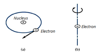
Figure: (a) Electron orbiting around the nucleus (b) Electron Spin

Figure: Circular current loop equivalent to electronic motion of electron
Without an external B field applied to the material, the sum of m, s is zero due to random orientation as in Figure (a). When an external B field is applied, the magnetic moments of the electrons more or less align themselves with B so that the net magnetic moment is not zero, as illustrated in Figure (b).
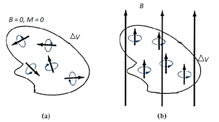
Figure: Magnetic dipole moment in a volume  : (a) before B is applied (b) after B is applied.
Permeability
The phenomenon of magnetism and electromagnetism depends on certain property of material called as permeability. Every medium is supposed to have two permeabilities.
a) Absolute permeability 
b) Relative permeability  0
0
To measure  r vacuum or free space is chosen. It has an absolute permeability of 4
 x 10-7 H/m. For any other medium
 =
=  0
0  r
r
Examples
Que) The amount of flux present in around magnetic bar was measured at 0.013 weber. If the material has a diameter of 14cm, calculate the flux density.
Sol: Area= r2
r2
Diameter=2r
r=14/2=7cm=0.07m
Area=3.14 x 0.072=0.0154m2
Flux Density B== A=0.013/0.0154=0.843 Tesla
Que) Calculate the radius of the material having flux density of 0.5 T and flux present around the magnetic bar is 0.02T.
Sol: Flux Density B= A
A
A=  B=0.02/0.5=0.04 m2
Area= r2
r2
r=0.113m
Que) A wire 2.5m long is bent into a square and into a circle. If the current flowing through the wire is 100 A, find the magnetising force at the centre of the square and the centre of the circle?
Sol: Value of h at centre of square will be H= =
=  =144 AT/m
Value of H at the centre of circle is H=I/2 r
r
=125.6AT/m
Que) Calculate the magnetising force and flux density at a distance of 4cm from a long straight circular conductor carrying a current of 250A and placed in air?
Sol: H=I/2 r
r
=250/2 x 0.04=994.71 AT/m
B= μoH
=4 x10-7x994.71=1.25x10⁻³ Wb/m2
Examples
Que) The amount of flux present in around magnetic bar was measured at 0.013 weber. If the material has a diameter of 14cm, calculate the flux density.
Sol: Area= r2
r2
Diameter=2r
r=14/2=7cm=0.07m
Area=3.14 x 0.072=0.0154m2
Flux Density B== A=0.013/0.0154=0.843 Tesla
Que) Calculate the radius of the material having flux density of 0.5 T and flux present around the magnetic bar is 0.02T.
Sol: Flux Density B= A
A
A=  B=0.02/0.5=0.04 m2
Area= r2
r2
r=0.113m
Que) A wire 2.5m long is bent into a square and into a circle. If the current flowing through the wire is 100 A, find the magnetising force at the centre of the square and the centre of the circle?
Sol: Value of h at centre of square will be H= =
=  =144 AT/m
Value of H at the centre of circle is H=I/2 r
r
=125.6AT/m
Que) Calculate the magnetising force and flux density at a distance of 4cm from a long straight circular conductor carrying a current of 250A and placed in air?
Sol: H=I/2 r
r
=250/2 x 0.04=994.71 AT/m
B= μoH
=4 x10-7x994.71=1.25x10⁻³ Wb/m2
Q) Find the H field within the slab when it is (a) permanently magnetized with magnetization Moi, (b) a linear permeable material with permeability A.
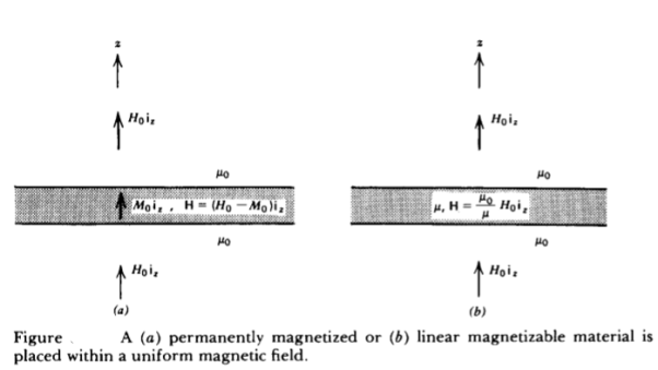
A) For both cases, requires that the B field across the boundaries be continuous as it is normally incident. (a) For the permanently magnetized slab, this requires that
 oH0 =
oH0 =  o(H+M0)
H=H0-M0
Note that when there is no externally applied field (Ho = 0), the resulting field within the slab is oppositely directed to the magnetization so that B = 0.
(b) For a linear permeable medium requires
 oH0 =
oH0 =  o(H)
o(H)
H=  o/
o/ ) H0
) H0
For  >
>  o the internal magnetic field is reduced. If H0 is set to zero, the magnetic field within the slab is also zero.
Consider two stationary loops of wire, labeled 1 and 2—see Figure. Let us run a steady current I1 around the first loop to produce a magnetic field B1. Some of the field-lines of B1 will pass through the second loop. Let Φ2 be the flux of B1 through loop 2

Where dS2 is a surface element of loop 2. This flux is generally quite difficult to calculate exactly (unless the two loops have a particularly simple geometry). However, we can infer from the Biot-Savart law,

That the magnitude of B1 is proportional to the current I1. This is ultimately a consequence of the linearity of Maxwell’s equations. Here, dl1 is a line element of loop 1 located at position vector r1. It follows that the flux Φ2 must also be proportional to I1.
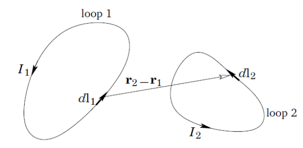
Thus, we can write
Φ2 = M21 I1,
Where M21 is a constant of proportionality. This constant is called the mutual inductance of the two loops.
Let us write the magnetic field B1 in terms of a vector potential A1, so that
B1 = ∇×A1.
It follows from Stokes’ theorem that

Where dl2 is a line element of loop 2. However, we know that

The above equation is just a special case of the more general law,

For j(r1) = dl1 I1/dl1 dA and d3r _ = dl1 dA, where dA is the cross sectional area of loop 1. Thus,

Where r2 is the position vector of the line element dl2 of loop 2, which implies that

In fact, mutual inductances are rarely worked out using the above formula, because it is usually much too difficult. However, this expression— which is known as the Neumann formula—tells us two important things. Firstly, the mutual inductance of two current loops is a purely geometric quantity, having to do with the sizes, shapes, and relative orientations of the loops. Secondly, the integral is unchanged if we switch the roles of loops 1 and 2. In other words,
M21 = M12.
Hence, we can drop the subscripts, and just call both these quantities M.
This is a rather surprising result. It implies that no matter what the shapes and relative positions of the two loops, the magnetic flux through loop 2 when we run a current I around loop 1 is exactly the same as the flux through loop 1 when we run the same current around loop 2.
We have seen that a current I flowing around some wire loop, 1, generates a magnetic flux linking some other loop, 2. However, flux is also generated through the first loop. As before, the magnetic field, and, therefore, the flux, Φ, is proportional to the current, so we can write
Φ = L I.
The constant of proportionality L is called the self-inductance. Like M it only depends on the geometry of the loop. Inductance is measured in SI units called henries (H): 1 henry is 1 volt-second per ampere. The henry, like the farad, is a rather unwieldy unit, since inductors in electrical circuits typically have inductances of order one micro-henry.
References:
- W.H. Hayt, “Engineering Electromagnetics”, TMH Publication 2006
- N.N. Rao Electromagnetic Engg. V Edition, Prentice Hall. 2005
- Fawwaz T. Ulaby Applied Electromagnetics, Prentice Hall. 1999
- Krauss Electromagnetic Engg. IV Edition, Tata Mc Graw Hill. 2003
- Shevgaonkar Electromagnetic Waves, Tata Mc Graw Hill 2002