Unit - 5
Boundary conditions, Maxwell’s equation and wave propagation
To derive normal and tangential boundary conditions for magnetostatics:
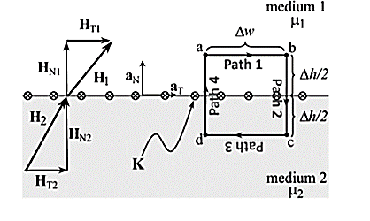
According to Ampere’s circuit law:
 dL = I enc
The current enclosed by the path is

Break H into four Integrals
 =Kw
=Kw
Path 1: =
=  T1 a T dL a T = H T1
Path 2:  N1 aN dL aN +
  N2 aN dL aN = -(HN1 + HN2)
Path 3:  dL =
dL =  T2aT dLaT= -HT2
Path 4:  dL =
dL =  N2dL aN+
  N1 a NdL aN = (H N1 + H N2)
Combing the results, we get
 dL = Ienc

Tangential BC = HT1 – HT2 = K
A more general expression for the first magnetostatic boundary condition can be written as

Where a21 is a unit vector normal going from media 2 to media 1.
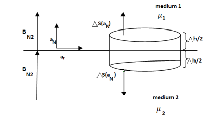
Gauss’s Law for Magnetostatic fields:
 ds = 0
To find the second boundary condition, we center a Gaussian pillbox across the interface as shown in Figure.
We can shrink h such that the flux out of the side of the pillbox is negligible.
Then we have

For normal BC

Thus, we see that the normal component of the magnetic flux density must be continuous across the boundary.
B N1 = B N2

We can say that
H N1 ≠ H N2
Problem:
The magnetic field intensity is given as H1 = 6ax + 2ay + 3az (A/m) in a medium with mr1 = 6000 that exists for z < 0. We want to find H2 in a medium with mr2 = 3000 for z >0.
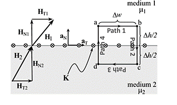
Step (a) and (b): The first step is to break H1 into its normal component (a) and its tangential component (b).
Step (c): With no current at the interface, the tangential component is the same on both sides of the boundary.
Step (d): Next, we find BN1 by multiplying HN1 by the permeability in medium 1.
Step (e): This normal component B is the same on both sides of the boundary.
Step (f): Then we can find HN2 by dividing BN2 by the permeability of medium 2.
Step (g): The last step is to sum the fields.
- First law: whenever flux linkage with the coil changes an emf is induced in that conductor
- Second law: the magnitude of induced emf is equal to the rate of change of flux linkage
Explanation: suppose a coil has n turns and flux through it change from initial value of Ø1 to Ø2 in line t sec
Initial flux linkage = N Ø
Final flux linkage = NØ2
 Induced emf
Putting the above equation in differential form
e = rate of change of flux linkage

The direction of this induced emf is given by lenis law which states the polarity of induced emf is always such that it tends to set up a current which flow in such a direction so as to oppose the cause that produces it.

Displacement Current: Derivation & Its Properties
In electromagnetic theory, the phenomenon of the magnetic field can be explained concerning a change in the electric field. The magnetic field is produced in the surroundings of the electric current (conduction current). Since the electric current might be in the steady-state or varying state. The concept displacement current depends on the variation of time of the electric field E, developed by the British physicist James Clerk Maxwell in the 19th century. He proved that the displacement current is another kind of current, proportional to the rate of change of electric fields and also explained mathematically. Let’s discuss the displacement current formula and necessity in this article.
What is the Displacement Current?
The sort of current created as a result of the rate of electric displacement field D is known as displacement current. It's a time-varying quantity that Maxwell's equations introduce. It's explained in terms of electric current density units. The law of Ampere circuits introduces it.
Ampere is the SI unit for displacement current (Amp). This dimension can be measured in length units, which can be maximum, minimum, or equivalent to the actual distance travelled from start to finish.
Derivation
Consider the fundamental circuit that gives the displacement current in a capacitor to understand the displacement current formula, dimensions, and derivation of displacement current.
Consider a parallel plate capacitor with a power supply requirement. When power is applied to the capacitor, it begins to charge and there is no current flow at first. The capacitor charges continually and builds above the plates as time passes. A change in the electric field between the plates during the charging of a capacitor over time causes the displacement current.
From the given circuit, consider the area of the parallel plate capacitor = S
Displacement current = Id
Jd = displacement current density
d= €E ie., related to electric field E
€ = permittivity of the medium between the plates of a capacitor
The displacement current formula of a capacitor is given as,
Id= Jd × S = S [dD / dt]
Since Jd = dD/dt
The displacement current will have the same unit and effect on the magnetic field as the conduction current, according to Maxwell's equation.
▽×H=J+Jd
Where,
H = magnetic field B as B=μH
μ = permeability of the medium in between the plates of a capacitor
J = conducting current density.
Jd =displacement current density.
As we know that ▽(▽×H) =0 and ▽. J=−∂ρ/∂t=−▽(∂D/∂t)
By using Gauss’s law that is ▽. D=ρ
Here, ρ = electric charge density.
Hence, we can conclude that, Jd=∂D/∂t displacement current density and it is necessary to balance RHS with LHS of the equation.
Properties
The following are the properties of displacement current: • It is a vector quantity that obeys the continuity property in a closed path. • It varies with the rate of change of current in an electric density field.
• When the current in a wire's electric field is constant, it gives zero magnitudes.
• An electric field's fluctuating time is a factor.
• It had a positive, negative, or zero magnitude with both direction and magnitude.
• Regardless of the path, the length of this can be taken as the shortest distance between the starting and ending points.
• It can be measured in length units.
• It has a minimum, maximum, or equivalent magnitude of displacement to the actual distance from the spot for a certain period.
• It is dependent on the presence of an electromagnetic field.
• When the starting and finishing points are the same, it returns zero.
The static electric field  exist without a magnetic field
  demonstrated by a capacitor with static charge Q.
Similarly, a conductor with constant current I has magnetic field  in absence of an electric field
  .
.
But in time varying fields  cannot exist without each other.
Maxwell’s equations are nothing but set of four expressions derived from Ampere’s circuit law, Farady’s law, Gauss’s law for electric field and Gauss’s law for magnetic field.
- Maxwell’s equation derived from Faradays law:
According to the concept from electrostatic field the work done over a closed path or closed contour that is stating point same as terminating point is always zero.
Mathematically it can be represented as
 -----------------------(1)
The above equation is called integral form of Maxwell’s equation derived from Faradays law of static field.
Using Stroke’s theorem converting close line integral into surface integral we get


But  cannot be zero which means
  = 0.
= 0.
Point form of Maxwell’s equation derived from differential form.
- Maxwell’s equation derived from Ampere’s Circuital Law:
According to the basic concept of magnetostatics an Amper’s circuital law states that the line integral of magnetic field intensity  around closed path is exactly equal to direct current enclosed by that path.
Mathematically 
Now the current enclosed is equal to the product of current density normal to the closed path and area of closed path. Hence, we get
 where
where
Hence evaluating the above equations, we get

The above expression is integral form of Maxwell’s equation from Ampere circuital law for static field.
Now by applying Stoke’s theorem LHS of the equation can be converted into surface integral

Hence, we get

- Maxwell’s equation derived from Gauss Law:
According to Gauss law of electrostatic fields the electric flux through any closed surface is equal to the total charge enclosed by that surface. Mathematically we can write
 1
1
The most common form to represent Gauss law mathematically is volume charge density Pv hence, we can write
 ----2
----2
The above equation is called integral form of Maxwell’s equation derived from Gauss Law.
To establish the relationship between  and Pv converting closed surface integral into volume integral using divergence theorem as
 ----3
----3
Comparing 2 and 3 we get

- Maxwell’s equation derived from Gauss Law for Magnetostatic field.
According to Gauss law for magneto static field the magnetic flux cannot reside in closed surface due to non-existence of single magnetic pole.
Mathematically we can write

The above equation is called Integral form of Maxwell’s equation derived from Gauss law for static magnetic field.
Now using divergence theorem we can write


Now dV cannot be zero that means  .
.
Key takeaway
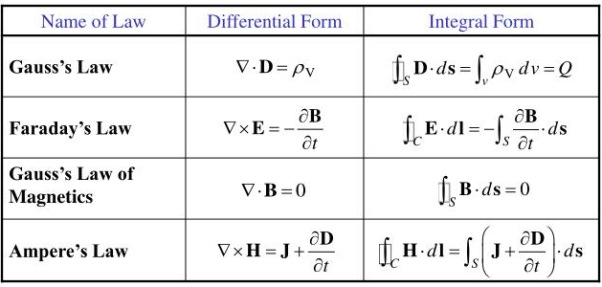
Ampere's circuit law states that the line integral of H around a closed path is the same as the net current Ienc enclosed by the path.
In other words, it can be said that the circulation of H equals Ienc:
 …. (1)
Ampere's law is similar to Gauss's law, since Ampere's law is easily applied to determine H when the current distribution is symmetrical.
Ampere’s law is a special case of Biot-Savart’s Law, it can be derived from Biot-Savart’s Law.
By applying Stokes's theorem to the left-hand side of equation 1, we get:

But

If we compare the two surface integrals, then:
 …….(2)
This is the third Maxwell Equation; it is essentially Ampere's law in differential
Form, whereas eq. 1 is the integral form.
Also, in Eq. 2  ; that is a magnetostatic field is not conservative.
For time varying Magnetic Fields, (2) is written as:

The term  is known as displacement current density.
Magnetic Flux Density
The magnetic flux density B is similar to the electric flux density D. As D =  in free space, the magnetic flux density B is related to the magnetic field intensity H as:
B = ……..(1)
Where  is a constant known as the permeability of free space. The constant is in henrys per meter (H/m) and has the value of

The magnetic Flux through a surface S is given by:
 …….(2)
Where the magnetic flux  ' is in webers (Wb) and the magnetic flux density is in webers per square meter (Wb/m2) or Tesla’s (T).
Unlike electric flux lines, magnetic flux lines always close upon themselves. This is because it is not possible to have isolated magnetic poles (or magnetic charges).
 ……….(3)
This equation is referred to as the law of conservation of magnetic flux or Gauss's law for magnetostatic fields. Although the magnetostatic field is not conservative, magnetic flux is conserved.
By applying Divergence Theorem to equation 3, we obtain:
 ………..(4)
This equation is the fourth Maxwell's equation. It also shows that magnetostatic fields have no sources or sinks. It means that magnetic field lines are always continuous.
Problem:
The following four vector fields are given in Cartesian co-ordinate system. The vector field, which does not satisfy the property of magnetic flux density, is
(a) 

(c) 

Solution
As we know that divergence of magnetic field is zero, therefore B=0
For  the above relation becomes


From the given options, option(c) does not satisfy the above relation.
Hence the correct option is (c)
Wave propagation in loss dielectrics
The imperfect conductors are called as lossy dielectrics. They are basically poor insulators where the free charges conduct to some extent. Here  which means the conductor is imperfect as well as the dielectric.
The equation for propagation constant will now be


We can calculate the values of  by substituting values of
  . The propagation constant for lossy medium is defined by the above equation. The value of intrinsic impedance for this medium is given as
η =
Since 
η = |η| ohms
ohms
Because of the complex quantity, η is represented in polar form as shown in the above equation where Өn is the phase angle difference between electric and magnetic fields. Thus, in lossy dielectric medium there exist a phase difference between the electric and magnetic fields.
The intrinsic impedance can be expressed as
η = 
=  /
/  (1 + (σ/
  )]
)]
η = (√ (µ/ є)) (1 / √ (1 – j (σ/  )) ohms
And the angle Өn is given as
Өn = ½ [(π/2) – tan-1 ( / σ)]
/ σ)]
This angle depends on the frequency of the signal as well as properties of the lossy dielectric medium. Then, w becomes very small for a low frequency signal. Thus, the phase angle is given as
Өn = (π/4)
For very high frequency signal, w becomes very large then,
Өn = 0
So, the range of Өn of a lossy dielectric for complete frequency range is 0 Өn (π/4)
Plane waves in lossless dielectrics
Reflection by perfect dielectric- normal incidence
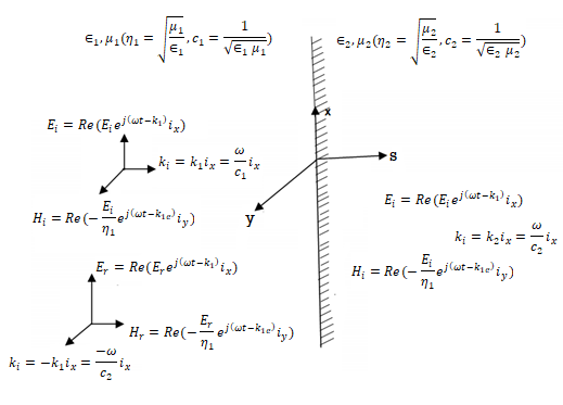
The perfect conductor with a lossless dielectric of permittivity  and permeability
  , as in Figure with a uniform plane wave normally incident from a medium
  with permittivity and permeability
  . In addition to the incident and reflected fields for z 0.
The unknown quantities  and
and  can be found from the boundary conditions of continuity tangential E and H at z=0,


From which we find reflection R and transmission field T field co-efficients as


Where 1 + R = T.
Plane wave in free space
In an electromagnetic wave, electric and magnetic field vectors are perpendicular to each other and at the same time are perpendicular to the direction of propagation of the wave. This nature of electromagnetic wave is known as Transverse nature.
Maxwell proved that both the electric and magnetic fields are perpendicular to each other in the direction of wave propagation. He considered an electromagnetic wave propagating along positive x-axis. When a rectangular parallelepiped was placed parallel to the three co-ordinate axis, the electric and magnetic fields propagate sinusoidal with the x-axis and are independent of y and z-axis.
A wave in which the values of variable are constant in a plane perpendicular to the direction of propagation of the wave is called plane wave. These planes may also termed as wave fronts.
Solutions of Maxwell’s Equations - Uniform Plane Waves
The sources of time varying electromagnetic fields are time varying charges and currents, whether man-made or naturally occurring. However, examination of Maxwell’s equations shows that, even in empty space (with no sources), and fields cause each other. This means that, although these fields must originate in source regions, they can propagate through source-free regions. Because solutions in source regions are very hard to obtain, let us consider what kind of fields can exist in source-free regions.

These equations are still very complicated (4 different partial derivatives). Let’s try to find simple solutions. We do this by making assumptions. After finding simplest solutions, we:
(i) Find what kind of source would generate this type of field (waves).
(ii) Show that these simple solutions are useful approximations to real electromagnetic waves.
Assumption for Solution:
Can we find a solution such that:
1.) No variation exists in x and y directions.
2.)  or
or  also is oriented along one of the axes.
Ampere’s Law becomes:

Or, with our assumptions:

Compare for transmission line:

In a similar manner,
 ………….(1)
Faraday’s Law becomes:
 ………….(2)
Thus, if  is only in the
  direction, then is only in the. If we differentiate (2) with respect to z, we get:

Substitute from (2),

We get

This is called the wave equation.
Compare for transmission line: (same).

We will assume dielectric media; lossless:

Dimensional analysis:


In the units we are using:
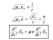
By exactly the same method, we also get:
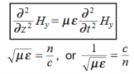
For example, the same equation is true for  and
and  . Thus,
  and
and  must have the same type of functional dependence. This wave equation still has many possible solutions. In fact, it can be shown by direct substitution that

Are the solutions

t is important to note that f1 and f2 can be any function.
The field we find directly from the equation:

Suppose
 …………(3)
Differentiate (3) with respect to z
 …………(4)
Integrate with respect to time
 …………(5)

This leads to a new quantity that relates the electric and magnetic fields:


Rewriting:
Units of  =
=  =
=  = Ω
= Ω
 0 = Impedance of free space =
  =377 Ω
 = impedance of a lossless dielectric =
  =
= =
= 
Note that  and
and  are in time phase and space quadrature
The directions of the vectors are such that:

This vector  , always points in the direction of propagation. These types of waves are called Uniform Plane Electromagnetic Waves.
“Plane” refers to the fact that, at any instant in time, the surfaces of constant phase are planes (here, constant).
“Uniform” means no variation in transverse direction. The wave derived here is one oscillating at a single frequency. The frequency is determined by the source. If the source has multiple frequencies, so will the wave. In communications, modulating a carrier wave results in multiple frequencies. But before we can study such fields, we must thoroughly understand single frequency sinusoidal waves.
Key Takeaways
- A wave in which the values of variable are constant in a plane perpendicular to the direction of propagation of the wave is called plane wave. These planes may also be termed as wave fronts.
- This vector
 , always points in the direction of propagation. These types of waves are called Uniform Plane Electromagnetic Waves.
Plain waves in good conductors
A uniform plane wave with x-directed electric field is normally incident upon a perfectly conducting plane at z =0, as shown in Figure. The presence of the boundary gives rise to a reflected wave that propagates in the -z direction. There are no fields within the perfect conductor. The known incident fields traveling in the +z direction can be written as


While the reflected fields propagating in the -z direction are similarly


Where in the lossless free space

The minus sign difference in the spatial exponential phase factors of (1) and (2) as the waves are traveling in opposite directions. The amplitude of incident and reflected magnetic fields are given by the ratio of electric field amplitude to the wave impedance.
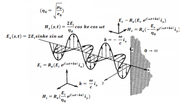
The negative sign in front of the reflected magnetic field for the wave in the -z direction arises because the power flow S, = E, x H, in the reflected wave must also be in the -z direction. The total electric and magnetic fields are just the sum of the incident and reflected fields. The only unknown parameter E, can be evaluated from the boundary condition at z =0 where the tangential component of E must be continuous and thus zero along the perfect conductor:
The total fields are the sum of incident and reflected fields

=
=

=
=
The electric and magnetic fields are 90* out of phase with each other both in time and space.
Poynting theorem states that the net power flowing out of a given volume V is equal to the time rate of decrease of stored electromagnetic energy in that volume decreased by the conduction losses is the total power leaving the volume = rate of decrease of stored electromagnetic energy ohmic power dissipated due to motion of charge.
Proof:
The energy density carried by the electromagnetic wave can be calculated using Maxwell's equations


 (5)
(5)
 (6)
(6)
 (7)
(7)


=

So from equation (vii) 
 (viii)
Integrating equation (viii) over a volume V enclosed by a surface S

Or 
As 
Or 
Or 
Or 
That is the Total power leaving the volume = rate of decrease of stored e.m.f energy - ohmic power dissipated due to charge motion
This equation (ix) represents the poynting theorem according to which the net power flowing out of a given volume is equal to the rate of decrease of stored electromagnetic energy in that volume minus the conduction losses.
When an alternating current pass through a conductor it does not flow uniformly all over the conductor. The concentration of current is higher on the surface of the conductor than at the centre, thus increasing the effective resistance. This effect is called the skin effect which is prominent at the higher frequency. The skin effect increases with the increase of cross section and permeability of conductor and reduced in stranded conductors.
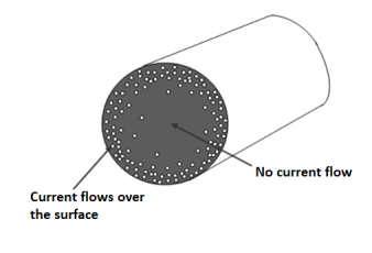
The solid conductor considered can be thought of having a number of strands one over the other, each carrying some portion of the current, so the inductance of the each stand will be vary and will increase towards the center. The high reactance of the strands near the center will increase the tendency of the current to flow with greater density near the outer stands. This result in a more power loss for a given r.m.s value of current, or the effective resistance is increased, also skin effect decreases the effective internal reactance. According to Maxwell and Rayleigh, the ratios of skin-effect resistance to direct current resistance and the skin-effect reactance to direct current reactance are given as:
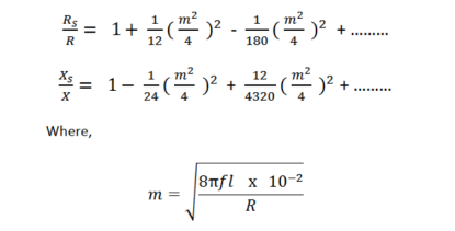
Hence the skin effect resistance and reactance depend upon frequency. For high-frequency currents, the skin effect predominates. The above formulae are not much used practically. For practical purpose the value of m is given as.

The empirical formula for Rs are:

The Skin effect depends upon the following factors:
- Nature of material.
- It is directly proportional to diameter of conductor.
- It is proportional to frequency of supply. Skin effect increases with the increase in frequency.
- It Depends on the shape of the conductor. Skin effect less for standerd conductor than the solid conductor.
References:
- W.H. Hayt, “Engineering Electromagnetics”, TMH Publication 2006
- N.N.Rao Electromagnetic Engg. V Edition, Prentice Hall. 2005
- Fawwaz T.Ulaby Applied Electromagnetics, Prentice Hall. 1999
- Krauss Electromagnetic Engg. IV Edition, Tata Mc Graw Hill. 2003
- Shevgaonkar Electromagnetic Waves, Tata Mc Graw Hill 2002