Unit - 2
Per Unit Representation
Major components of a power system are- synchronous generators, synchronising equipment, circuit breakers, isolators, earthing switches, bus-bars, transformers, transmission lines, current transformers, potential transformers, relay and protection equipment, lightning arresters, station transformer, motors for driving auxiliaries in power station. Some of the components will be discussed here as shown in Fig.

Component 1: Synchronous Generators: The synchronous generators used in generating stations are revolving field type owing to its inherent advantages. The synchronous generators, based on the type of prime movers to which they are mechanically coupled, may be classified as: (i) Hydro-generators (ii) Turbo-generators, and (iii) Diesel engine driven generators.
Power Transformers: Power transformers are used for stepping-up the voltage for transmission at generating stations and for stepping-down voltage for further distribution at main step-down transformer substations. Usually naturally cooled, oil immersed, known as ON type, two winding, three-phase transformers, are used up to the rating of 10 MVA. The transformers of rating higher than 10 MVA are usually air blast cooled. For very high rating, the forced oil, water cooling and air blast cooling may be used. For regulating voltage, the transformers used are provided with on load tap changer.
Switchgear: Everyone is familiar with low voltage switches and rewirable fuses. A switch is used for opening and closing of an electric circuit while a fuse is used for over-current protection. Every electric circuit needs a switching device and protective device. Switching and protective devices have been developed in different forms. Switchgear is a general term covering a wide range of equipment concerned with switching and protection.
Circuit Breakers: Circuit breakers are mechanical devices designed to close or open contact members, thus closing or opening of an electrical circuit under normal or abnormal conditions. Automatic circuit breakers, which are usually employed for the protection of electrical circuits, are equipped with a trip coil connected to a relay or other means, designed to open the breaker automatically under abnormal conditions, such as over-current.
Isolators: Since isolators (or isolating switches) are employed only for isolating circuit when the current has already been interrupted, they are simple pieces of equipment. They ensure that the current is not switched into the circuit until everything is in order. Isolators or disconnect switches operate under no load condition. They are not equipped with arc quenching devices. They do not have any specified current breaking capacity or current making capacity. The isolators in some cases are used for breaking charging current of transmission line.
Earthing Switch: Earthing switch is connected between the line conductor and earth. Normally it is open and it is closed to discharge the voltage trapped on the isolated or disconnected line. When the line is disconnected from the supply end, there is some voltage on the line to which the capacitance between the line and earth is charged.
This voltage is significant in hv systems. Before commencement of maintenance work it is necessary that these voltages are discharged to earth by closing the earthing switch. Normally, the earthing switches are mounted on the frame of the isolator.
Component # 3. Bus-Bars:
Bus-bar (or bus in short) term is used for a main bar or conductor carrying an electric current to which many connections may be made. Bus-bars are merely convenient means of connecting switches and other equipment into various arrangements. The usual arrangement of connections in most of the substations permits working on almost any piece of equipment without interruption to incoming or outgoing feeders. In some arrangements two buses are provided to which the incoming or outgoing feeders and the principal equipment may be connected. One bus is usually called the ―main‖ bus and the other ―auxiliary‖ or ―transfer‖ bus. The main bus may have a more elaborate system of measuring instruments, relays etc. associated with it. The switches used for connecting feeders or equipment to one bus or the other are called ―selector‖ or ―transfer‖ switches. Bus-bars may be of copper, aluminium or steel.
Copper has a comparatively low resistivity and also the advantage of relatively high mechanical strength; this makes it economical to use copper bus-bars in installations of very large capacity where the currents are particularly heavy. During 1960‘s the need for substituting the copper with aluminium became very urgent, particularly in countries like India where copper is imported. Now aluminium is being increasingly used for various switchgear installations due to its numerous advantages over copper such as higher conductivity on weight basis, lower cost for equal current carrying capacity, excellent corrosion resistance and ease of formability.
Component # 4. Lightning Arresters:
The lightning arrester is a surge diverter and is used for the protection of power system against the high voltage surges. It is connected between the line and earth and so diverts the incoming high voltage wave to the earth. Lightning arresters act as safety valves designed to discharge electric surges resulting from lightning strokes, switching or other disturbances, which would otherwise flash-over insulators or puncture insulation, resulting in a line outage end possible failure of equipment. They are designed to absorb enough transient energy to prevent dangerous reflections and to cut off the flow of power-frequency follow (or dynamic) current at the first current zero after the discharge of the transient. They include one or more sets of gaps to establish the breakdown voltage, aid in interrupting the power follow current, and prevent any flow of current under normal conditions (except that gap shunting resistors, when used to assure equal distribution of voltage across the gaps, permits a very small leakage current). Either resistance (valve) elements to limit the power follow current to values the gaps can interrupt, or an additional arc extinguishing chamber to interrupt the power follow current are connected in series with gaps. Arresters have a short time lag of breakdown compared with the insulation of apparatus, the breakdown voltage being nearly independent of the steepness of the wave front.
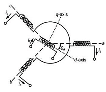
The schematic diagram of a synchronous generator is shown in Figure. This contains three stator windings that are spatially distributed. It is assumed that the windings are wye-connected. The winding currents are denoted by ia, ib and ic. The rotor contains the field winding the current through which is denoted by if. The field winding is aligned with the so-called direct (d) axis. We also define a quadrature (q) axis that leads the d -axis by 90°. The angle between the d-axis and the a-phase of the stator winding is denoted by θd.
Let the self-inductance of the stator windings be denoted by Laa, Lbb, Lcc such that
Ls= Laa = Lbb = Lcc
And the mutual inductance between the windings be denoted as

The mutual inductances between the field coil and the stator windings vary as a function of θd and are given by


The self-inductance of the field coil is denoted by Lff. The flux linkage equations are then given by


For balanced operation we have
ia+ ib+ ic =0
Hence the flux linkage equations for the stator windings


For steady state operation we can assume

Also, assuming that the rotor rotates at synchronous speed ωs we obtain the following two equations


Where θd0 is the initial position of the field winding with respect to the phase-a of the stator winding at time t = 0. The mutual inductance of the field winding with all the three stator windings will vary as a function of θd, i.e.,


Since we assume balanced operation, we need to treat only one phase. Let the armature resistance of the generator be R. The generator terminal voltage is given by

Where the negative sign is used for generating mode of operation in which the current leaves the terminal.

The internal emf ea that is given by

Where the rms magnitude Ei is proportional to the field current

Since θd0 is the position of the d -axis at time t = 0, we define the position of the q -axis at that instant as


The equivalent circuit is shown in Fig. Let the current ia lag the internal emf ea by θa. The stator currents are then


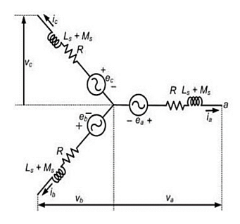
The single-phase equivalent circuit is shown in Fig. The phase angle θa between ea and ia is rather difficult to measure under load as ea is the no load voltage. To avoid this, we define the phase angle between νa and ia to be θ. We assume that ea leads νa by δ. Therefore, we can write

Then the voltages and currents shown in Fig. Below are given as


The synchronous impedance is then defined as


The terminal voltage equation is then

Let us consider TL (with characteristic impedance Zo) where the end is terminated with a resistive that is real load.

Figure. Mismatch
The solution for this is to place a matching network between the line and the load.

Figure. Matching network
The quarter-wave transformer is simply a transmission line with characteristic impedance Z1 and length l = λ/4 (i.e., a quarter-wave line).

Figure. λ/4 matching network
We know that the input impedance of the quarter wavelength line is:
Zin = (Z1) 2/ ZL = (Z1) 2/ RL
Thus, if we wish for Zin to be numerically equal to Z0, we find:
Zin = (Z1) 2/ RL = Zo
Solving for Z1, we find its required value to be:
Z1 = √Zo RL
Therefore, a λ/4 line with characteristic impedance 𝑍1 =  𝑍0𝑅𝐿 will match a transmission line with characteristic impedance Z0 to a resistive load RL
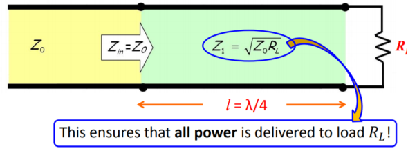
Figure. Power delivered to load.
Single-Stub Matching Technique
A stub is a short-circuited section of a transmission line connected in parallel to the main transmission line. A stub of appropriate length is placed at some distance from the load such that the impedance seen beyond the stub is equal to the characteristic impedance. Suppose we have a load impedance connected to a transmission line with characteristic impedance. The objective here is that no reflection should be seen by the generator. In other words, even if there are standing waves in the vicinity of the load, the standing waves must vanish beyond certain distance from the load. Conceptually this can be achieved by adding a stub to the main line such that the reflected wave from the short-circuit end of the stub and the reflected wave from the load on the main line completely cancel each other at point B to give no net reflected wave beyond point B towards the generator. We make use of Smith chart for this purpose

Fig. Single Stub Matching Technique
Since we have a parallel connection of transmission lines, it is more convenient to solve the problem using admittances rather than impedances. To convert the impedance into admittance also we make use of the Smith chart and avoid any analytical calculation. Now onwards treat the Smith chart as the admittance chart
Matching Procedure
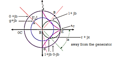
First mark the load admittance on the admittance smith chart (A). Plot the constant
 circle on the smith chart. Move on the constant
  circle till you intersect the constant g=1 circle this point of intersection corresponds to point 1+jb’ (B). The distance traversed on the constant circle is l1. This is the location of placing the stub on the transmission line from the load end. Find constant susceptance jb’ circle. Find mirror image of the circle to get -jb’ circle. Mark 0-jb’ on the outer most circle (D). From (D) move circular clockwise up to s.c point (E) to get the stub length ls.
Key Takeaway:
A quarter-wave transformer is a simple impedance transformer which is commonly used in impedance matching in order to minimize the energy which is reflected when a transmission line is connected to a load.
LOAD FREQUENCY CONTROL
The following basic requirements are to be fulfilled for successful operation of the system:
1. The generation must be adequate to meet all the load demand
2. The system frequency must be maintained within narrow and rigid limits.
3. The system voltage profile must be maintained within reasonable limits and
4. In case of interconnected operation, the tie line power flows must be maintained at the specified values.
When real power balance between generation and demand is achieved the frequency specification is automatically satisfied. Similarly, with a balance between reactive power generation and demand, voltage profile is also maintained within the prescribed limits. Under steady state conditions, the total real power generation in the system equals the total MW demand plus real power losses. Any difference is immediately indicated by a change in speed or frequency.
Generators are fitted with speed governors which will have varying characteristics: different sensitivities, dead bands response times and droops. They adjust the input to match the demand within their limits. Any change in local demand within permissible limits is absorbed by generators in the system in a random fashion. An independent aim of the automatic generation control is to reschedule the generation changes to preselected machines in the system after the governors have accommodated the load change in a random manner.
Thus, additional or supplementary regulation devices are needed along with governors for proper regulation. The control of generation in this manner is termed load-frequency control. For interconnected operation, the last of the four requirements mentioned earlier is fulfilled by deriving an error signal from the deviations in the specified tie-line power flows to the neighboring utilities and adding this signal to the control signal of the load-frequency control system. Should the generation be not adequate to balance the load demand, it is imperative that one of the following alternatives be considered for keeping the system in operating condition:
I. Starting fast peaking units.
2. Load shedding for unimportant loads, and
3. Generation rescheduling.
It is apparent from the above that since the voltage specifications are not stringent. Load frequency control is by far the most important in power system control.
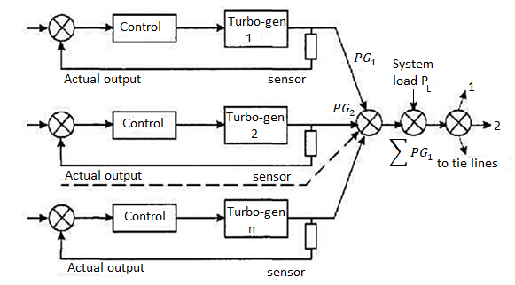
In order to understand the mechanism of frequency control, consider a small step increase in load. The initial distribution of the load increment is determined by the system impedance; and the instantaneous relative generator rotor positions. The energy required to supply the load increment is drawn from the kinetic energy of the rotating machines. As a result, the system frequency drops. The distribution of load during this period among the various machines is determined by the inertias of the rotors of the generators partaking in the process. This problem is studied in stability analysis of the system. After the speed or frequency fall due to reduction in stored energy in the rotors has taken place, the drop is sensed by the governors and they divide the load increment between the machines as determined by the droops of the respective governor characteristics.
METHODS OF VOLTAGE CONTROL
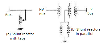
Reactors: Inductive reactors absorb reactive power and may be used in circuits, series or shunt connected, while series connected reactors are used to limit fault currents, shunt reactors are used for var control. Reactors installed at line ends and intermediate substations can compensate up to 70% of charging power while the remaining 30% power at no-load can be provided by the under excited operation of the generator. With increase in load, generator excitation may be increased with reactors gradually cut-out. Figure shows some typical shunt reactor arrangements.
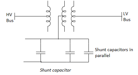
Shunt Capacitors: Capacitors produce var and may be connected in series or shunt in the system. Series capacitors compensate the line reactance in long overhead lines and thus improve the stability limit. However, they give rise to additional problems like high voltage transients, sub synchronous resonance, etc. Shunt capacitors are used for reactive compensation. Simplicity and low cost are the chief considerations for using shunt capacitor. Further, for expanding systems additions can be made. Fig. Shows the connected of shunt capacitors through the tertiary of a transformer.
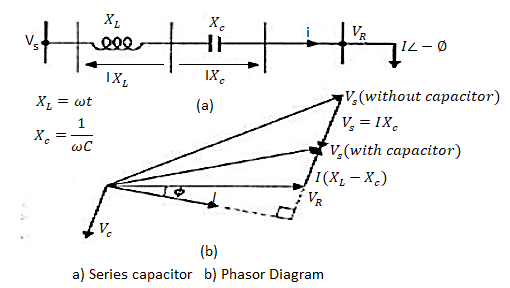
Series capacitors:
Here the capacitors are connected in series with the line. The main aim is to reduce the inductive reactance between supply point and the load. The major disadvantage of the method is, whenever short circuit current flows through the capacitor, protective devices like spark gaps and non linear resistors are to be in corporates. Phasor diagram for a line with series capacitor is shown in the figure (b).
Relative merits between shunt and series capacitors.
1. If the load var requirement is small, series capacitors are of little help.
2. If the voltage drop is the limiting factor, series capacitors are effective; also to some extent the voltage fluctuations can be evened.
3. If the total line reactance is high, series capacitors are very effective and stability is improved.
4. With series capacitors the reduction in line current is small, hence if the thermal considerations limits the current, little advantage is from this, so shunt compensation is to be used.
Synchronous compensators:
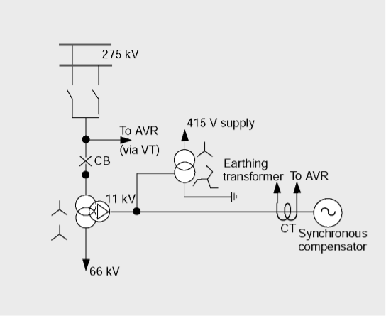
A synchronous compensator is a synchronous motor running without a mechanical load and depending on the excitation level; it can either absorb or generate reactive power. When used with a voltage regulator the compensator can automatically run overexcited at times of high loads and under excited at light loads. A typical connection of a compensator is shown in the figure along with the associated voltage – var output characteristics.
A great advantage of the method is the flexible operation for all load conditions. Being a rotating machine, its stored energy is useful for riding through transient disturbances, including voltage drops.
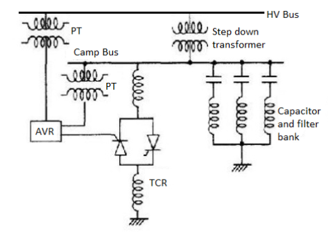
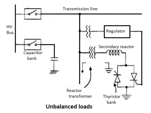
Even though the capacitors and reactors in are shown in figure connected to the low voltage side of a down transformer, the capacitor banks may be distributed between high and low voltage buses. The capacitor bank often includes, in part, harmonic filters which prevent the harmonic currents from flowing in the transformer and the high voltage system. Filters for the 5th and 7th harmonics are generally provided. The thyristor controlled reactor (TCR) is operated on the low voltage bus. In another form of the compensator illustrated in Figure the reactor compensator is connected to the secondary of a transformer. With this transformer, the reactive power can be adjusted to anywhere between 10% to the rated value. With a capacitor bank provided with steps, a full control range from capacitive to inductive power can be obtained. The reactor's transformer is directly connected to the line, so that no circuit breaker is needed.
Static VAR compensators:
In Recent years reactive compensation of charging power is made feasible with the application of 3-phase, thyristor, and power controller circuits with automatic control functions.
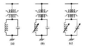
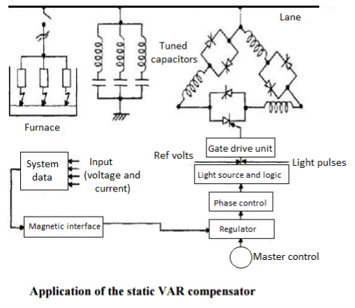
The term static var compensator is applied to a number of static var compensation devices for use in shunt reactive control. These devices consist of shunt connected, static reactive element (linear or non linear reactors and capacitors) configured into a var compensating system. Some possible configurations are shown in above Figure. Even though the capacitors and reactors in are shown in figure connected to the low voltage side of a down transformer, the capacitor banks may be distributed between high and low voltage buses. The capacitor bank often includes, in part, harmonic filters which prevent the harmonic currents from flowing in the transformer and the high voltage system. Filters for the 5th and 7th harmonics are generally provided. The thyristor controlled reactor (TCR) is operated on the low voltage bus. In another form of the compensator illustrated in Figure the reactor compensator is connected to the secondary of a transformer.
The primary winding is star connected with neutral grounded, suitable to the thyristor network. The secondary reactor is normally nonexistent, as it is more economical to design the reactor transformer with 200% leakage impedance between primary and secondary windings. The delta connected tertiary winding will effectively compensate the triple harmonics. The capacitor bank is normally subdivided and connected to the substation bus bar via one circuit breaker per sub bank. The regulator generates firing pulses for the thyristor network in such a way that the reactive power required to meet the control objective at the primary side of the compensator is obtained. The reactor transformer has a practically linear characteristic from no load to full load condition. Thus, even under all stained over voltages; hardly any harmonic content is generated due to saturation. The transformer core has non ferromagnetic .Gaps to the required linearity. The following requirements are to be borne in mind while designing a compensator.
1. Reaction should be possible, fast or slow, whenever demanded. No switching of capacitor should take place at that time to avoid additional transients in the system. Commutation from capacitor to reactor and vice versa should be fast.
2. No switching of the capacitors at the high voltage bus bar, so that no higher frequency Transients is produced at EHV level.
3. Elimination of higher harmonics on the secondary side and blocking them from entering the system. In a three phase system the thyristor controlled inductors are normally delta connected as shown in Figure to compensate unbalanced loads and the capacitors may be star or delta connected
In the thyristor controlled reactor, the inductive reactance is controlled by the thyristors. For a limited range of operation the relationship between the inductive current iL and the applied voltage V is represented in Figure. As the inductance is varied, the susceptance varies over a range within the limits BLmin and BLmax (corresponding to XLmax and XLmin) while the voltage Changes by v volts.
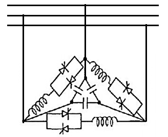
The current flowing in the inductance would be different in each half cycle, varying with the conduction angle such that each successive half cycle is a smaller segment of a sine wave. The fundamental component of inductor current is then reduced to each case. Quick control can be exercised within one half cycles, just by giving a proper step input to the firing angle control Static var compensators when installed reduce the voltage swings at the rolling mill and power system buses in drive system applications. They compensate for the average reactive power requirements and improve power factor. Electric arc furnaces impose extremely difficult service requirements on electrical power systems since the changes in arc furnace load impedance are rapid. Random and non symmetrical. The three phases of a static var compensator can be located independently so that it compensates for the unbalanced reactive load of the furnace and the thyristor controller will respond quickly in order to minimize the voltage fluctuations or voltage flicker seen by the system.
TYPES OF SVC
1. Variable impedance type
2. Current source type
3. Voltage source type
The followings are the basic types of reactive power control elements which makes all or parts of SVC Saturated reactor
1. Thyristor controlled Reactor
2. Thyristor switched capacitor
3. Thyristor Switched Reactor
4. Thyristor controlled Transformer
APPLICATION OF STATIC VAR COMPENSATOR
Connected to the power system, to regulate the transmission voltage ("Transmission SVC") Connected near large industrial loads, to improve power quality ("Industrial SVC")
Per unit system applied to single phase system
Voltage, current, volt ampere and impedance are so related that selection of base of any two quantities determines the base of remaining two quantities.
Let common mega volt ampere base = (MVA)B.
Base voltage on any section of power system=kV
Then the base current and base impedance can be calculated as


If the impedance of considered section is expressed in ohm, then


Similarly, Resistance and Reactance which are expressed in ohms can be written in pu system as


Advantages of per unit system
1) In per unit System, different voltage level at different components entirely disappears and power system components are expressed only as per unit impedance and voltage.
2) Impedance of machine are specified in terms of percentage of their ratings. Hence, converting it to common base enables for comparison of parameters.
3) It simplifies the computation of power system. The chance of confusion between line and phase values in a balanced three phase system is less.
4) The Per unit impedance referred to either side of transformer is same regardless of their connection.
5) Per unit system is not suitable for computer using digital computers.
Drawbacks of per unit system
1) Some equations that hold good in unscaled cases are modified when scaled into the Per unit system as factors such as √3and 3 are removed.
Solved Examples
Example 1-
A 30 MVA, 11kV generator has a reactance of 0.2 referred to its ratings as bases. Determine per unit reactance when referred to base kVA, new 50000 kVA and base kV of 33kV.
Soln. Old base KVA = 30000kVA
(MVA)B = 30 MVA
Old base kV = 11 kV
Old per unit impedance, Zpu old = 0.2 pu
New base kVA = 50000 KVA
(MVA)B new = 50 MVA


Example-2
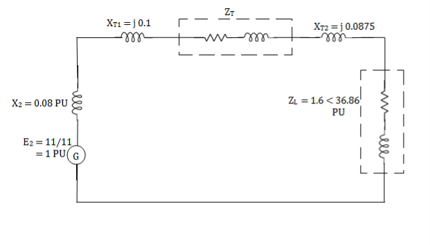
The following system represents a single line diagram of power system. The rating of connected component are given on a single line diagram. Choose 100 MVA common base and 11KV as voltage base on generator site. Draw per unit impedance diagram.


Generator-


Transformer 1-

Transformer 2-

Load-


Load impedance, 


Transmission line-


Example-3
If the resistance in ohm is 5 ohm, find the Per unit value. Given base KVA =10 and base kV=11.
Soln. Base kVA = 10
(MVA)B = 10×10-3 (kV)B = 11


Example-4
A single phase transformer is rated as 2.5kVA, 11/0.4 kV. If the leakage reactance is 0.96ohm when referred to low voltage side, then determine its leakage reactance in per unit.
Soln. (kVA)B = 2.5, (MVA)B = 2.5 ×10⁻³ (kV)B = 0.4


Example-5
Draw the Per unit impedance diagram for the power system shown, neglect resistance and user base of 100MVA, 220kV in 50 ohm line. The rating of the generator motor and transformers are: Generator: 40 MVA, 25kV, X = 20%
Motor: 50MVA, 11kV, X =30%
 : 40 MVA, 33
 -220
-220 kV, X=15%
 30 MVA, 11
 - 220
- 220 kV, X=15%
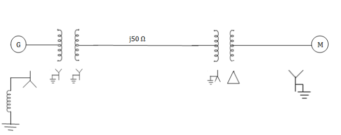
Soln. (MVA)B =100MVA, (kV)B = 220 kV


Example 6
A simple power system is shown in figure. Redraw the system when per unit impedances are represented on a common 5,000 VA base and common system base voltage of 250V.
Soln. Base MVA = 5×10⁻³ MVA
Base kV for generator circuit = 250×10-3 kV
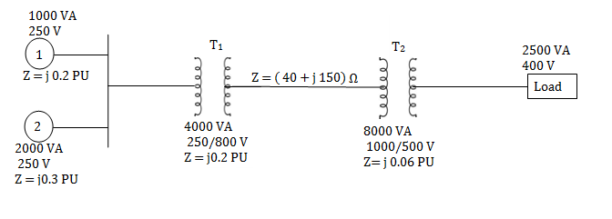
Per unit impedances of machine 1 and 2


Per unit reactance of Transformer T1


Per unit reactance of Transformer T2

Per unit load MVA (pu) = 2.5/5 = 0.5 pu

Example-7
For the system shown in the figure determine the generator voltage. Take the base as 100 MVA, 15kV on generator terminals.

Soln. MVAB = 100 MVA
KVB = 15 kV on generator terminals
Generator-


Load-


Actual generator terminal voltage,


References:
1. I. J. Nagrath, D. P. Kothari, Power System Engineering, Tata McGraw-Hill publications, 2008
2. Ashfaq Husain, Electrical Power System, CBS Publication, 5th Edition
3. C. L. Wadhwa, Electrical Power Systems, New Age International Publisher, 6th Edition
4. V. K. Mehta and Rohit Mehta, Principles of Power System, S. Chand Publication, 2008