Unit - 3
Overhead Transmission Lines and Cables
An overhead line may be used to transmit or distribute electric power. The successful operation of an overhead line depends to a great extent upon the mechanical design of the line. In general, the main components of an overhead line are:
(i) Conductors which carry electric power from the sending end station to the receiving end station.
(ii) Supports which may be poles or towers and keep the conductors at a suitable level above the ground.
(iii) Insulators which are attached to supports and insulate the conductors from the ground.
(iv) Cross arms which provide support to the insulators.
(v) Miscellaneous items such as phase plates, danger plates, lightning arrestors, anti-climbing wires etc.
Key Takeaways:
An overhead power line is a structure used in electric power transmission and distribution to transmit electrical energy across large distances.
An overhead line may be used to transfer or distribute electric power. The proper overhead line operation depends to a big extent upon its mechanical design. While constructing an overhead line, it has to be verified that line mechanical strength is such so as to provide against the most probable weather conditions. Typically, the main elements of an overhead line are:
- Conductors which transfer power from the sending end station to the receiving end station.
- Supports which may be poles or towers. They keep the conductors at an appropriate level above the earth.
- Insulators that are connected to supports and insulate the conductors from the earth. - Cross arms which give support to the insulators.
- Miscellaneous elements such as phase plates, danger plates, surge arrestors, etc.
The overhead line operation continuity depends upon the judicious selection of above elements. Hence, it is beneficial to have detailed discussion on them.
Overhead Line Conductor Materials
The conductor is one of the crucial items as most of the financial outlay is invested for it. Hence, correct selection of conductor material and size is of significant importance. The conductor material used for transmission and distribution of electric power needs to have the following characteristics:
- High tensile strength in order to sustain mechanical stresses
- High electrical conductivity
- Low specific gravity so that weight per unit volume is small
- Low cost so that it can be used for considerable distances
All above demands cannot be found in a single material. Hence, while choosing a conductor material for a particular application, a compromise is made between the cost and the needed electrical and mechanical characteristics.
Typically used conductor materials
Typically used conductor materials for overhead lines are copper, aluminium, steel cored aluminium, galvanised steel and cadmium copper. The selection of a particular material is dependent on the cost, the needed electrical and mechanical characteristics and the local conditions. All conductors used for overhead lines are typically stranded in order to increase the flexibility. In stranded conductors, there is typically one central wire and around it, successive layers of wires containing 6, 12, 18, 24 ...... Wires. Therefore, if there are n layers, the overall number of individual wires is 3n(n+1) +1. In the production process of stranded conductors, the consecutive layers of wires are twisted or spiralled in different directions so that layers are bound together.
Copper
Copper is perfect material for overhead lines owing to its great electrical conductivity and increased tensile strength. It is typically used in the hard drawn form as stranded conductor. Even though hard drawing slightly decreases the electrical conductivity, it considerably increases the tensile strength. Copper has great current density. For example, the current carrying capacity of copper per unit of cross-sectional area is significant. This leads to two benefits. Firstly, smaller conductor cross-sectional area is needed and secondly, the area offered by the conductor to wind loads is decreased. Also, this metal is homogeneous, durable and has big scrap value. There is no doubt that copper is perfect material for electric power transmission and distribution. Nevertheless, due to its big cost and non-availability, it is not often used for these purposes. Current trend is to use aluminium instead of copper.
Aluminium.
Aluminium is cheap and light in comparison to copper but it has considerably smaller conductivity and tensile strength. The relative comparison of the two materials is as follows:
The aluminium conductivity is 60% that of copper. The lower aluminium conductivity means that for any specific transmission efficiency, the conductor cross-sectional area must be bigger in aluminium than in copper. For the same resistance, the aluminium conductor diameter is around 1.26 times the copper conductor diameter. The increased aluminium cross section exposes a bigger surface to wind pressure and, hence, supporting towers have to be designed for greater transverse strength. Typically, this requires the use of higher towers with consequence of bigger sag.
The aluminium specific gravity (2.71 gm/cc) is lower than that of copper (8.9 gm/cc). Hence, an aluminium conductor has almost one-half the weight of equivalent copper conductor. Due to this, the supporting structures for aluminium need not be made so strong as that of copper conductor.
Aluminium conductor being light is liable to bigger swings and therefore bigger cross-arms are needed. Due to lower tensile strength and bigger co-efficient of linear expansion of aluminium, the sag is bigger in aluminium conductors.
Considering the overall characteristics that include cost, conductivity, tensile strength, weight etc., aluminium has an edge over copper. Hence, it is being predominantly used as a conductor material. It is especially profitable to use aluminium for heavy-current transmission where the conductor size is big and its cost forms a significant proportion of the total cost of complete installation.
Steel-cored aluminium
Due to low tensile strength, aluminium conductors have bigger sag. This forbids their application for bigger spans and makes them unsuitable for long distance transmission. In order to improve the tensile strength, the aluminium conductor is strengthened with a core of galvanised steel wires. The obtained composite conductor is known as steel-cored aluminium or ACSR (aluminium conductor steel reinforced). Steel-cored aluminium conductor has galvanised steel central core surrounded by a number of aluminium strands. Typically, diameter of both steel and aluminium wires is the same. Typically, the cross-section of the two metals is in the ratio of 1:6 but can be modified to 1:4 in order to get more conductor tensile strength. Figure. Presents steel-cored aluminium conductor having one steel wire surrounded by six aluminium wires. The result of this composite conductor is that steel core takes bigger percentage of mechanical strength while aluminium strands transfer the bulk of current.
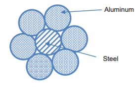
The steel-cored aluminium conductors have the following benefits:
- The reinforcement with steel improves the tensile strength but at the same time keeps the composite conductor light. Hence, steel-cored aluminium conductors will create smaller sag and therefore longer spans can be used.
- Due to smaller sag with steel-cored aluminium conductors, towers of smaller heights can be installed.
Galvanised steel
Steel has considerable tensile strength. Hence, galvanised steel conductors can be applied for long spans or for short line sections exposed to significantly high stresses due to climatic conditions. They are considered as very suitable in rural locations where cheapness is the main issue. Due to steel poor conductivity and high resistance, such conductors are not appropriate for transferring large power over a long distance. Nevertheless, they can be used to advantage for transferring a small power over a small distance where the size of the copper conductor desirable from economic considerations would be too small and therefore inappropriate for use because of poor mechanical strength.
Cadmium copper
The conductor material now being used in specific installations is copper alloyed with cadmium. An addition of 1% or 2% cadmium to copper improves the tensile strength by roughly 50% and the conductivity is only decreased by 15% below that of pure copper. Hence, cadmium copper conductor can be useful for extremely long spans. Nevertheless, due to cadmium high cost, such conductors will be economical only for lines of small cross-section i.e., where the cost of conductor material is relatively small in Aluminium Steel comparison with the support cost.
A steady direct current flowing via the conductors is uniformly disbursed over the complete move-section of the conductor. However, an alternating cutting-edge flowing via the conductor does no longer distribute uniformly, as an alternative it has a tendency to pay attention near the floor of the conductor as proven inside the figure. That is called skin effect in transmission line.
Skin effect in transmission line:
As a result, the tendency of an alternating current to pay attention close to the surface of the conductor is called skin impact in transmission line.
Due to proximity and skin impact, the powerful vicinity of the pass-phase of the conductor via which modern is to waft is decreased. This will increase the resistance of conductor while sporting an alternating current. The purpose of skin effect in transmission line is explained beneath:

Normally, a stranded conductor is used and each strand includes a small a part of the cutting-edge. Every conductor strand, close to the center, is surrounded by using a more magnetic flux and therefore has larger inductance than that strand close to the floor.
The high reactance (opposition) of inner stands restricts the float of modern-day inside the middle and causes it to float near the surface of the conductor which produces proximity and skin impact.
How to lessen proximity and skin effect in transmission line:
The proximity and skin impact in transmission line relies upon the subsequent elements:
Nature of material.
- The diameter of cord – the skin effect increases with the diameter of wire.
- The shape of cord – the skin effect is lesser for stranded conductor than the solid conductor.
- Frequency – the skin effect increases with the increase in frequency. Whilst the frequency is zero (dc), there's no inductance and for this reason the present day is uniformly allotted over the complete go-section of the conductor. No skin effect. It is profitable to mention here that skin effect is negligible while the frequency is much less (underneath 50 hz) and conductor diameter is small (beneath 1 cm).
By means of using these facts properly, skin effect may be decreased considerably.
Proximity effect in transmission lines:
Inside the proximity and skin impact, the flux installation inside the conductor itself turned into taken into consideration and it turned into assumed that there may be no other current sporting conductor close by. This flux produces a nonuniform distribution of cutting-edge in the conductor referred to as skin impact.
But, within the transmission traces, there are (one or) contemporary wearing conductors located nearby and their magnetic flux links with the conductor below attention. The effect of this flux is extra within the closer 1/2 of the conductor than the farther.
Whilst the conductors convey currents within the opposite directions the fields set-up will tend to purpose an increase in the modern density within the adjacent quantities whereas whilst the currents are within the identical instructions the modern density is increased within the farther components of the conductor. This outcome the distribution of present day in the conductor.
Hence, the flux installation by means of the nearby modern sporting conductor effects the distribution of current within the conductor. This impact is known as proximity impact in transmission lines. For this reason, the proximity effect in transmission strains additionally consequences within the boom in resistance of the conductor.
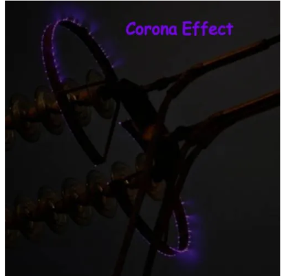
Corona discharge (additionally known as the corona impact) is an electrical discharge resulting from the ionization of a fluid such as air surrounding a conductor this is electrically charged. The corona impact will occur in excessive voltage systems except enough care is taken to limit the power of the encompassing electric powered subject.
Corona discharge can reason an audible hissing or cracking noise as it ionizes the air across the conductors. This is common in high voltage electric energy transmission traces. The corona impact can also produce a violet glow, manufacturing of ozone fuel across the conductor, radio interference, and electrical strength loss.
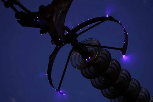
Fig. Corona discharge on a 500 kv overhead power line
What is the corona impact?
The corona effect occurs clearly due to the reality that air isn't always a super insulator – containing many free electrons and ions under ordinary situations. While an electric subject is installed in the air among conductors, the unfastened ions and electrons inside the air will enjoy a force. Because of this impact, the ions and loose electrons get improved and moved inside the opposite route.
The charged particles at some point of their motion collide with one another and also with gradual-transferring uncharged molecules. For this reason, the range of charged debris increases swiftly. If the electrical area is strong sufficient, a dielectric breakdown of air will arise and an arc will form among the conductors.
Electric powered energy transmission deals with the majority switch of electrical power, from generating stations located many kilometers far away from the principle consumption facilities or the cities. Because of this, the long-distance transmission conductors are of maximum necessity for effective electricity switch – which in-certainly consequences in big losses across the system.
Minimizing these energy losses has been a chief project for strength engineers. Corona discharge can appreciably reduce the efficiency of ehv (extra excessive voltage) strains in strength systems.
Two elements are crucial for corona discharge to arise:
Alternating electric ability difference ought to be supplied across the line.
The spacing of the conductors, should be big sufficient compared to the line diameter.
Corona discharge:
When an alternating current is made to glide across two conductors of a transmission line whose spacing is huge compared to their diameters, the air surrounding the conductors (composed of ions) is subjected to dielectric strain.
At low values of the deliver voltage, not anything takes place because the strain is just too small to ionize the air out of doors. But when the ability distinction increases past some threshold fee (known as the essential disruptive voltage), the field strength will become sturdy enough for the air surrounding the conductors to dissociated into ions – making it conductive. This crucial disruptive voltage takes place at approximately 30 kv.
The ionized air effects in electric discharge across the conductors (due to the float of these ions). This gives upward push to a faint luminescent glow, together with the hissing sound followed via the liberation of ozone.
This phenomenon of electrical discharge happening in high voltage transmission lines is referred to as the corona impact. If the voltage across the lines continues to growth, the glow and hissing noise becomes increasingly extreme – inducing an excessive strength loss into the gadget.
Elements affecting corona loss:
The line voltage of the conductor is the principle figuring out aspect for corona discharge in transmission lines. At low values of voltage (lesser than the essential disruptive voltage) the stress at the air is not excessive enough to purpose dielectric breakdown – and hence no electric discharge occurs.
With increasing voltage, the corona effect in a transmission line takes place due to the ionization of atmospheric air surrounding the conductors – it is especially stricken by the conditions of the cable in addition to the bodily nation of the environment. The primary
Factors affecting corona discharge are:
- Atmospheric conditions
- Condition of conductors
- Spacing among conductors
Atmospheric conditions:
We've got proved that the voltage gradient for dielectric breakdown of air is directly proportional to the density of air. As a result, in a stormy day, because of continuous air float, the quantity of ions present surrounding the conductor is a way extra than normal, and hence it’s much more likely to have electric discharge in transmission traces on this type of day, in comparison to an afternoon with the pretty clear weather. The device needs to be designed thinking about those intense situations.
Circumstance of conductors:
This specific phenomenon relies upon highly at the conductors and its physical circumstance. It has an inverse proportionality courting with the diameter of the conductors. I.E., with the boom in diameter, the effect of corona on strength device reduces substantially. Also, the presence of dust or roughness of the conductor reduces the critical breakdown voltage, making the conductors greater prone to corona losses. As a result, in maximum cities and business areas having excessive pollution, this component is of affordable importance to counter the unwell consequences it has on the machine.
Spacing among conductors:
As already cited, for corona to arise within the spacing between the strains correctly have to be tons better in comparison to its diameter, however if the duration receives accelerated past a sure limit, the dielectric pressure at the air reduces, and therefore, the impact of corona reduces as well. If the spacing is made too huge, then corona for that place of the transmission line might not arise at all.
Lowering corona discharge
Corona discharge always consequences in electricity loss. Energy is lost in the shape of mild, sound, warmness, and chemical reactions. Although those losses are personally small, through the years they are able to add as much as massive energy loss in high voltage networks.
Corona discharge can be reduced via:
Growing the conductor size: a larger conductor diameter consequence in a lower in the corona impact.
Increasing the distance among conductors: growing conductor spacing decreases the corona effect.
Using bundled conductors: bundled conductors increase the effective diameter of the conductor – hence decreasing the corona effect.
The use of corona rings: the electrical subject is more potent wherein there is a sharp conductor curvature. Because of this corona discharge happens first at the pointy factors, edges, and corners. Corona earrings reduce the corona effect by ‘rounding out’ conductors (i.e., Making them much less sharp). They may be used on the terminals of very excessive voltage gadget (including on the bushings of high voltage transformers). A corona ring is electrically connected to the excessive voltage conductor, encircling the factors wherein the corona effect is maximum probably to arise. This encircling appreciably reduces the sharpness of the floor of the conductor – dispensing the charge across a wider vicinity. This in turn reduces corona discharge.
The interchange of conductor positions of a transmission line at regular intervals along the route is known as Transposition of Conductors. In the power transmission line when the line conductors are asymmetrically spaced i.e. not equally spaced, the inductance of each phase is different causing voltage drops of different magnitudes in the three phases even if the system is operating under balanced condition (load currents are balanced in the three phases). Also the magnetic field external to the conductors is not zero thereby inducing voltages in adjacent communication lines and causing what is known as “telecommunication interference”. This can be overcome by the interchange of conductor positions at regular intervals along the route and this practice is known as “transposition of conductors”.
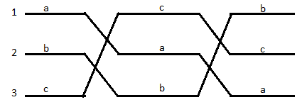
In a transposed transmission line each of the three conductors occupies all the three positions relative to other conductors (position 1, position 2, and position 3) for one-third of the total length of the transmission line. Transposition also balances out the line capacitance so that electro-statically induced voltages are also balanced. Figure shows the transposition of conductors over a complete cycle.
Single stranded conductors are used in transmission gadget normally as much as 220 kv. But it isn't viable to use single-stranded conductor for the voltage above 220 kv systems.
For extremely excessive voltage system, hollow conductor can be used to optimize the go with the flow of present day through it. But erection and protection of hollow conductors inside the ∑hv machine aren't low cost.
The problem may be solved via the usage of bundled conductors in preference to hole conductor inside the electric transmission gadget above 220 kv voltage level.
What's bundled conductor?
We name bundled conductor to the ones conductors which form from or greater stranded conductors, bundled collectively to get more modern carrying potential.
Right here, we use or greater stranded conductors consistent with phase. Also, to boom the modern-day wearing capability of the device, a bundle conductor additionally contributes numerous facilities to the electrical transmission machine.
A bundled conductor reduces the reactance of the electrical transmission line. It additionally reduces voltage gradient, corona loss, radio interference, surge impedance of the transmission lines.
Via making bundle conductor, the geometric imply radius (gmr) of the conductor improved. As the self gmr of the conductor increases, the inductance of the conductor decreases. Theoretically, there is an ultimate sub-conductor spacing in package deal conductor on the way to supply minimal voltage gradient on the floor of package deal conductor. The superior spacing among sub-conductors for decreasing voltage gradient is 8 to 10 instances of the diameter of the conductor.
Because the voltage gradient receives decreased, the radio interference additionally receives reduced.
As the inductance of the bundled conductor is reduced, the surge impedance of the line is decreased have become the components of surge impedance is
In which l is the inductance according to phase in keeping with unit duration, and c is the capacitance per phase consistent with unit length of the transmission line.
Because the surge impedance gets decreased because of bundling the conductor, the surge impedance loading, of the conductor gets extended. Accelerated surge impedance loading makes the transmission potential of the system more.
To this point we've got mentioned three-segment systems which have handiest one conductor in step with phase. But for extra excessive voltage strains corona causes a big trouble if the conductor has best one conductor consistent with phase. Corona takes place when the floor ability gradient of a conductor exceeds the dielectric strength of the encompassing air. This causes ionization of the place near the conductor.
Corona produces electricity loss. It also reasons interference with conversation channels. Corona manifests itself with a hissing sound and ozone discharge. Due to the fact most long-distance electricity strains in India are both 220 kv or 400 kv, avoidance of the occurrence of corona is perfect.
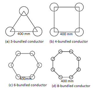
The excessive voltage surface gradient is reduced significantly via having two or extra conductors in line with segment in close proximity. That is known as conductor bundling. The conductors are bundled in corporations of two, 3 or four as proven in fig. 1.10. The conductors of a package deal are separated at normal periods with spacer dampers that save you clashing of the conductors and save you them from swaying within the wind. In addition, they connect the conductors in parallel.
The geometric mean radius (gmr) of -conductor bundle is given by means of

In which ds is the gmr of conductor. The gmr for 3-conductor and four-conductor bundles are given respectively by means of


The inductance of the bundled conductor is then given by way of
Where n=2,3 ....

Wherein the geometric imply distance is calculated assuming that the center of a round conductor is the same as that of the middle of the package.
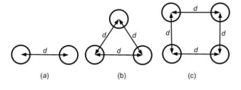
Fig. Bundled conductors: (a) 2-conductor, (b) 3-conductor and (c) 4-conductor bundles
Key Takeaways:
A bundled conductor reduces the reactance of the electric transmission line.
There are 5 varieties of insulators utilized in transmission traces as overhead insulation:
- Pin insulator
- Suspension insulator
- Stress insulator
- Stay insulator
- Shackle insulator
Pin, suspension, and strain insulators are utilized in medium to excessive voltage structures. At the same time as live and shackle insulators are specifically used in low voltage applications.
Pin insulator
Pin insulators are the earliest developed overhead insulator, but are nonetheless typically utilized in strength networks up to 33 kv system. Pin kind insulator may be one component, parts or three parts kinds, relying upon utility voltage.
In an eleven kv device we normally use one part type insulator wherein entire pin insulator is one piece of properly shaped porcelain or glass.
Because the leakage direction of insulator is through its surface, it is suitable to increase the vertical length of the insulator surface location for lengthening leakage route. We offer one, or more rain sheds or petticoats on the insulator frame to obtain long leakage direction.
Similarly to that rain shed or petticoats on an insulator serve another motive. We layout those rain sheds or petticoats in any such manner that at the same time as raining the outer floor of the rain shed turns into wet however the internal floor stays dry and non-conductive. So there might be discontinuations of carrying out path via the damp pin insulator surface.
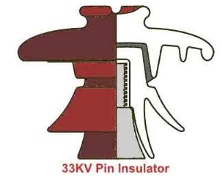
In better voltage systems – like 33kv and 66kv – manufacturing of one element porcelain pin insulator turns into greater difficult. The higher the voltage, the thicker the insulator have to be to offer sufficient insulation. A very thick unmarried piece porcelain insulator isn't realistic to manufacture.
In this example, we use a couple of element pin insulator, in which some well-designed porcelain shells are constant collectively by using Portland cement to shape one complete insulator unit. We commonly use components pin insulators for 33kv, and 3 parts pin insulators for 66kv systems.
Designing consideration of electrical insulator:
The live conductor attached to the pinnacle of the pin insulator which is at the stay ability. We restore the bottom of the insulator to helping shape of earth capacity. The insulator has to resist the capability stresses among conductor and earth. The shortest distance among conductor and earth, surrounding the insulator body, along which electric discharge can also take region thru the air, is known as flashover distance.
When the insulator is moist, its outer floor becomes almost undertaking. For this reason the flashover distance of insulator is reduced. The design of an electrical insulator has to be such that the decrease of flashover distance is minimal when the insulator is wet.
That is why the uppermost petticoat of a pin insulator has umbrella kind designed so that it can shield, the rest lower a part of the insulator from the rain. The top floor of the topmost petticoat is willing as less as possible to maintain most flashover voltage all through raining.
The rain sheds are made in this type of manner that they must now not disturb the voltage distribution.
They're so designed that their subsurface at a proper angle to the electromagnetic lines of pressure.
Post insulator
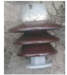
Post insulators are just like pin insulators, however publish insulators are more suitable for higher voltage programs.
Post insulators have a better wide variety of petticoats and a greater height as compared to pin insulators. We will mount this type of insulator on helping structure horizontally in addition to vertically. The insulator is fabricated from one piece of porcelain and it has clamp association are in both pinnacle and backside stop for fixing.
Suspension insulator
In better voltage, past 33kv, it becomes uneconomical to apply pin insulator because length, weight of the insulator become more. Managing and changing larger length single unit insulator are quite hard assignment. For overcoming these problems, suspension insulator became developed.
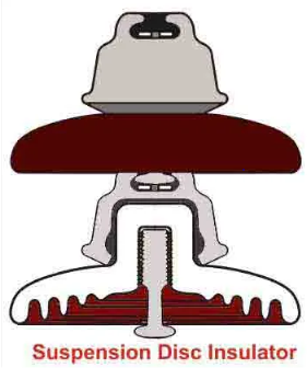
In suspension insulator numbers of insulators are related in series to form a string and the road conductor is carried with the aid of the bottom maximum insulator. Each insulator of a suspension string is known as disc insulator because of their disc like shape.
Strain insulator
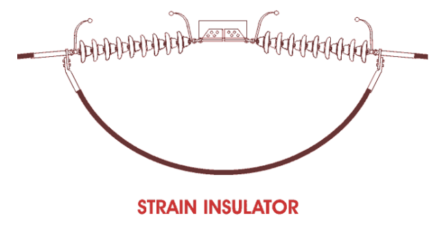
While suspension string is used to sustain excellent tensile load of conductor it is referred as string insulator. Whilst there may be a dead quit or there may be a pointy nook in transmission line, the line has to sustain a tremendous tensile load of conductor or stress. A stress insulator need to have vast mechanical power in addition to the important electrical insulating homes.
Stay insulator

For low voltage strains, the stays are to be insulated from ground at a top. The insulator used inside the live cord is called as the live insulator and is normally of porcelain and is so designed that during case of breakage of the insulator the guy-cord will now not fall to the ground.
Shackle insulator or spool insulator

The shackle insulator (also known as a spool insulator) is commonly utilized in low voltage distribution network. It can be used in both the horizontal or vertical positions. The use of such insulator has reduced recently after increasing the using of underground cable for distribution reason.
The tapered hole of the spool insulator distributes the burden more lightly and minimizes the possibility of breakage when heavily loaded. The conductor within the groove of shackle insulator is fixed with the help of smooth binding cord.
String efficiency
The ratio of voltage across the whole string to the product of number of discs and the voltage across the disc nearest to the conductor is known as string efficiency i.e.,
String efficiency = Voltage across the string / n x Voltage across disc nearest to conductor
Methods of improving string efficiency
The various methods for this purpose are:
1.By using longer cross-arms. The value of String Efficiency of Insulator depends upon the value of K that is ratio of shunt capacitance to mutual capacitance. In order to reduce shunt capacitance, the distance of conductor from tower must be increased that is longer cross-arms should be used.
2.By grading the insulators. In this method, insulators of different dimensions are so chosen that each has a different capacitance. The insulators are capacitance graded that is they are assembled in the string in such a way that the top unit has the minimum capacitance, increasing progressively as the bottom unit that is nearest to conductor is reached. Since voltage is inversely proportional to capacitance, this method tends to equalize the potential distribution across the units in the string.
3.By using a guard ring. The potential across each unit in a string can be equalized by using a guard ring which is metal ring electrically connected to the conductor and surrounding the bottom insulator. The guard ring introduces capacitance between metal fittings and the line conductor.. The guard ring is contoured in such a way that shunt capacitance currents i1,i2 etc. are equal to metal fitting line capacitance currents i′1,i′2 etc. The result is that same charging current I flows through each unit of string. Consequently, there will be uniform potential distribution across the units.
Key Takeaways:
The string efficiency is defined as the ratio of voltage across the string to the product of the number of strings and the voltage across the unit adjacent string.
Considering single phase line consisting of conductors (phase and neutral) a and b of identical radius r. They're located at a distance d meters. The cross sections of conductors are proven in the diagram below.
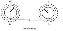
Let the current go with the flow in the conductors are opposite in direction in order that one will become return path for the alternative.
The flux linkages of conductor ‘a’ is given through the formulation

Inductance-of-two-wire here,
Ia = +i
Ib = -i
Daa = r’
Dab = d
Substituting those values in above equation


Similarly, the flux linkages with the conductor ‘b’ is

Flux linkages inductance of the conductor ‘a’

Similarly, the inductance of conductor ‘b’

Inductance per conductor

Inductance of both the conductors is given via the formula,
Loop inductance =

The inductance of a man or woman conductor is one-half of the whole inductance of a two-twire line.
GMD stands for geometrical mean distance.
This concept could be very beneficial in electricity machine for the calculation of inductance and capacitance of transmission line.
Essentially, as we know that geometrical imply of n numbers a1, a2, a3…., anis
(a1a2a3a4…. An)1/n
The equal idea is likewise used for the calculation of gmd and gmr. In gmd we take the geometrical suggest of distances between the strands of transmission lines whilst in gmr, geometrical mean of distances between the stands of a single composite conductor are calculated.
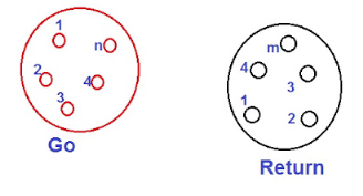
Let us assume composite conductors used in transmission line as proven in parent below.
As shown within the parent above, one conductor is cross and any other is return for present day for unmarried section line. The cutting-edge is believed to be similarly divided amongst all of the strands of a conductor.
Therefore,
Cutting-edge carried by way of each strand in cross conductor = i/n
Present day carried via every strand in go back conductor = -i/m
Right here i is the entire current carried through each conductor.
Now, we will calculate the gmd and gmr for the configuration of the conductors proven in parent above.
For buying the gmd, first we need to calculate the gap among the strands of move and go back conductors.
Let,
D11 = distance between the 1ststrand of cross and return conductor
D12 = distance among the 1ststrand of cross and second strand of return conductor
D21 = distance among the 2nd strand of move and 1st strand of return conductor
Dmn = distance among the mth strand of cross and nth strand of return conductor
Thus, the Geometrical mean of above distances i.e., GMD,

Geometrical imply radius of a solid conductor or a strand of radius r is described because the factious radius r’ having no inner flux linkage however having the same inductance because the original conductor of radius r.
R ‘= 0.7788r
Consider the single-phase line consisting of two round conductors as shown in Figure. The separation between the conductors is D.
Let us assume that conductor 1 carries a charge of q1 C/m while conductor 2 carries a charge q2 C/m. The presence of the second conductor and the ground will disturb field of the first conductor. However we assume that the distance of separation between the conductors is much larger compared to the radius of the conductor and the height of the conductor is much larger than D for the ground to disturb the flux.
Therefore, the distortion is small and the charge is uniformly distributed on the surface of the conductor.
Assuming that the conductor 1 alone has the charge q1, the voltage between the conductors is
V12(q1) = q1/ 2 π 0 ln D / r1 ---------------------------------------------------------(1)
Similarly if the conductor 2 alone has the charge q2, the voltage between the conductors is
V21(q2) = q2/ 2 π 0 ln D / r2
The above equation implies that
V12 (q2) = q2/ / 2 π 0 ln r2/D --------------------------------------------------(2)
From the principle of super position we can write
V12 = V12(q1)+V12(q2) = q1/ 2 π 0 ln D / r1 + q2/ / 2 π 0 ln r2/D ------------(3)
For a single-phase line let us assume that q1 (= -q2 ) is equal to q . We therefore have
V12 = q/ 2 π 0 ln D / r1 - q/ / 2 π 0 ln r2/D = q/ 2 π 0 ln D 2 / r1 r2 -------------(4)
Assuming r1 = r2= r3, we can rewrite (4) as
V12 = = q/ π 0 ln D / r ----------------------------------------------------(5)
Therefore the capacitance between the conductors is given by
C12 = π 0 ln D / r F/m -----------------------------------------------------(6)
The above equation gives the capacitance between two conductors.
For the purpose of transmission line modeling, the capacitance is defined between the conductor and neutral. This is shown in Figure. Therefore, the value of the capacitance is given from Figure as
C=2C12 =2 π 0 / ln (D / r) F/m ------------------------------------------------(7)

Fig (a) Capacitance between two conductors (b) Equivalent capacitance to ground
Capacitance of single phase line with effect of earth’s surface on electric field
Assume conductors A’ and B’ as image conductors of conductors A and B respectively, as shown in Figure. Let the height of conductors be h metres above the earth and charge of +q coulombs per metre length and -q coulombs per metre length on the conductors A and B respectively.
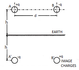
Fig. Single phase transmission lines
The equation for the voltage drop VAB as determined by two charged conductors A and B and their images A’ and B’ may be written as follows:
VAB = 1/ 2π 0 [ qa log e d/r + qb log e r/d + qa’ log e √4h2 + d2 / 2h + qb’ log e 2h/ √4h2 + d2 ] ----------------------------------------------------(8)
Substituting qA = q’B = + q and q’A = qB = -q we have,
VAB = q/ π 0 log e 2hd/ r √ 4h2 + d2
Capacitance between conductors A and B,
CAB = q/VAB = π 0 / log e d/ r√ 1+ d2/4h2 -----------------------(9)
The above expression for capacitance reveals that the presence of earth modifies the radius of conductor r to r √ ( 1 + d2 / 4 h2 )
The effect of earth on the capacitance of the system is to increase it. However, normally the distance of separation between the conductors is much smaller than the height of the conductor from the ground, therefore, r √ ( 1 + d2 / 4 h2 ) ≈ r and for all practical purposes the effect of earth on line capacitance can be neglected.
Key Takeaways:
For transmission line modelling purpose the capacitance is defined between the conductor and neutral
The overhead line conductors need to be supported on the poles or towers in such a way that conductor currents do not flow to ground through supports for example, line conductors have to be adequately insulated from supports. This is accomplished by securing line conductors to supports with the help of insulators. The insulators give necessary insulation between line conductors and supports and therefore prevent any leakage current from conductors to ground. Typically, the insulators need to have the following desirable features:
- Big mechanical strength in order to sustain conductor load, wind load etc.
- Big insulator material electrical resistance in order to avoid leakage currents to ground.
- Big insulator material relative permittivity in order that dielectric strength is high.
- The insulator material needs to be non-porous, free from impurities and cracks otherwise the permittivity will be decreased.
- Big ratio of puncture strength to flashover.
The most typically used material for insulators of overhead line is porcelain but glass, steatite and specific composition materials are also applied to a certain extent. Porcelain is made by firing at a high temperature a mixture of kaolin, feldspar and quartz. It is mechanically stronger than glass, gives less trouble from leakage and is less impacted by temperature changes.

Under operating conditions, the insulation of a cable is subjected to electrostatic forces. This is known as dielectric stress. The dielectric stress at any point in a cable is in fact the potential gradient (or electric intensity) at that point. Consider a single core cable with core diameter d and internal sheath diameter D. The electric intensity at a point x meters from the centre of the cable is

By definition, electric intensity is equal to potential gradient. Therefore, potential gradient g at a point x meters from the Centre of cable is


Potential difference V between conductor and sheath is


Substituting the value of Q, we get

It is clear from the above equation that potential gradient varies inversely as the distance x. Therefore, potential gradient will be maximum when x is minimum i.e., when x = d/2 or at the surface of the conductor. On the other hand, potential gradient will be minimum at x = D/2 or at sheath surface. Maximum potential gradient is

Minimum potential gradient is


The variation of stress in the dielectric is shown in Fig. It is clear that dielectric stress is maximum at the conductor surface and its value goes on decreasing as we move away from the conductor. It may be noted that maximum stress is an important consideration in the design of a cable. For instance, if a cable is to be operated at such a voltage that maximum stress is 5 kV/mm, then the insulation used must have a dielectric strength of at least 5 kV/mm, otherwise breakdown of the cable will become inevitable.
The process of achieving uniform electrostatic stress in the dielectric of cables is known as grading of cables. It has already been shown that electrostatic stress in a single core cable has a maximum value (gmax) at the conductor surface and goes on decreasing as we move towards the sheath. The maximum voltage that can be safely applied to a cable depends upon gmax i.e., electrostatic stress at the conductor surface. For safe working of a cable having homogeneous dielectric, the strength of dielectric must be more than gmax. If a dielectric of high strength is used for a cable, it is useful only near the conductor where stress is maximum. But as we move away from the conductor, the electrostatic stress decreases, so the dielectric will be unnecessarily over strong. The unequal stress distribution in a cable is undesirable for two reasons. Firstly, insulation of greater thickness is required which increases the cable size. Secondly, it may lead to the breakdown of insulation. In order to overcome above disadvantages, it is necessary to have a uniform stress distribution in cables. This can be achieved by distributing the stress in such a way that its value is increased in the outer layers of dielectric. This is known as grading of cables. The following are the two main methods of grading of cables:
- Capacitance grading
- Inter sheath grading
Capacitance Grading:
The process of achieving uniformity in the dielectric stress by using layers of different dielectrics is known as capacitance grading. In capacitance grading, the homogeneous dielectric is replaced by a composite dielectric. The composite dielectric consists of various layers of different dielectrics in such a manner that relative permittivity > r of any layer is inversely proportional to its distance from the center. Under such conditions, the value of potential gradient any point in the dielectric is constant and is independent of its distance from the center. In other words, the dielectric stress in the cable is same everywhere and the grading is ideal one. However, ideal grading requires the use of an infinite number of dielectrics which is an impossible task. In practice, two or three dielectrics are used in the decreasing order of permittivity, the dielectric of highest permittivity being used near the core. The capacitance grading can be explained beautifully by referring to the above Figure. There are three dielectrics of outer diameter d1, d2 and D and of relative permittivity >1, >2 and >3 respectively. If the permittivity are such that >1 > 2 > 3 and the three dielectrics are worked at the same maximum stress, then
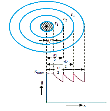


Total p.d. Between core and earthed sheath is
V = V1 + V2 + V3

Intersheath Grading:
In this method of cable grading, a homogeneous dielectric is used, but it is divided into various layers by placing metallic inters heaths between the core and lead sheath. The inter sheaths are held at suitable potentials which are in between the core potential and earth potential. This arrangement improves voltage distribution in the dielectric of the cable and consequently more uniform potential gradient is obtained.

Consider a cable of core diameter d and outer lead sheath of diameter D. Suppose that two intersheaths of diameters d1 and d2 are inserted into the homogeneous dielectric and maintained at some fixed potentials. Let V1, V2 and V3 respectively be the voltage between core and Intersheath 1, between inter sheath 1 and 2 and between inter sheath 2 and outer lead sheath. As there is a definite potential difference between the inner and outer layers of each inter sheath, therefore, each sheath can be treated like a homogeneous single core cable Maximum stress between core and inter sheath 1 is


Since the dielectric is homogeneous, the maximum stress in each layer is the same i.e.,


As the cable behaves like three capacitors in series, therefore, all the potentials are in phase i.e. Voltage between conductor and earthed lead sheath is
V = V1 + V2 + V3
Inter sheath grading has three principal disadvantages. Firstly, there are complications in fixing the sheath potentials. Secondly, the inter sheaths are likely to be damaged during transportation and installation which might result in local concentrations of potential gradient. Thirdly, there are considerable losses in the inter sheaths due to charging currents. For these reasons, inter sheath grading is rarely used.
Generally, PILC and XLPE cables are used in HT (High Tension) network, and oil or gas filled cables are used for EHV (Extra High Voltage) network. Proper cable end boxes shall be used for these cables. When the cable is not in use, both its ends should be properly sealed. PVC armoured cables are used for LT distribution. A gland should be used at the cable end to have earth continuity with armouring. It provides rigidity so that the cable does not swing and damage the insulation, and loose connection can be avoided.
Apply M-seal to avoid water entry in the cable. While selecting the cable capacity, the safety factor must be taken into consideration. Conductors used in underground cables are made of aluminium and copper. Generally XLPE (Cross-linked polyethylene) are used. The insulation of the cable must not deteriorate due to the high-voltage stress, ozone produced by electric discharges in air, or tracking. The cable system must prevent contact of the high-voltage conductor with other objects or persons, and must contain and control leakage current.

XLPE cable means cross-linked polyethylene insulated aluminium conductor armoured cable. In XLPE cable, stranded aluminium conductor is first screened in the form of a semi-conducting extrusion which provides a smooth conductor surface and prevents formation of cavities at the surface of the conductor when the cable is subjected to bending. The screened conductor is insulated with extruded XLPE compound. The insulation is further screened with layer of non-metallic semiconducting material and over that a non-magnetic metallic screen in the form of copper or aluminium tape is applied. An important advantage of XLPE as insulation for medium and high voltage cables is their low dielectric loss. The dielectric loss factor is about one decimal power lower than that of paper insulated cables and about two decimal powers lower than that of PVC insulated cables. Since the dielectric constant is also more favourable, the mutual capacitance of XLPE cables is also lower, thus reducing the charging currents and earth-leakage currents in networks without the rigid star point earthing.
References:
1. N.N.Rao Electromagnetic Engg. V Edition, Prentice Hall. 2005
2. Fawwaz T. Ulaby Applied Electromagnetics, Prentice Hall. 1999
3. Krauss Electromagnetic Engg. IV Edition, Tata Mc Graw Hill. 2003
4. Shevgaonkar Electromagnetic Waves, Tata Mc Graw Hill 2002
5. Matthew, N. O. Sadiku Elements of Electromagnetics, Oxford University publication, 6th edition, 2014.