Unit - 2
Effect of feedback on parameter variation
The feedback systems are having many advantages over the non-feedback system as we have seen earlier. So, some performance parameters can be controlled through this feedback system such as sensitivity, noise etc. Sensitivity is a parameter which forecasts the effectiveness of feedback in reducing the influence of these variations on system performance.
The output of the open loop system is given by
C(s) = G(s)R(s)
Now due to variation in parameters G(s) changes to [G(s)+G(s)]. The output will now become
C(s)+ C(s) = [G(s)+ G(s)] R(s)
C(s) = G(s)R(s)
For closed loop system the output is given as

Now due to variation in parameters it becomes

The above equation shows that if there is variation in parameters then G(s) is reduced by factor of 1+G(s)H(s). The variation in overall transfer function T(s) due to change in G(s) is defined as sensitivity.

When there is small change in G(s) then sensitivity becomes

 : Sensitivity of T w.r.t G
For closed loop system the sensitivity will be

For open loop system

As T=G
The sensitivity of T w.r.t H is given as

The above equation shows that for large values of GH sensitivity of the feedback system w.r.t H approaches to unity.
Key takeaway
For closed loop system the sensitivity w.r.t G is reduced by a factor of (1+GH) as compared to the open loop system.
The feedback helps to control the disturbances as they generate an error signal. The signal flow graph for closed loop system is given by
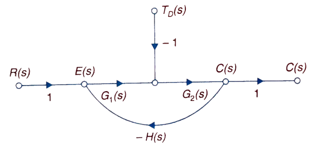
Fig 1 Closed loop system with disturbance signal
 =
= 
Where:
TD(s) = Disturbance signal.
For |G1G2H(s)|>>1 over the range of s
 =
=
The signal flow graph of a system with noise signal N(s) in the feedback path. The gain is given by
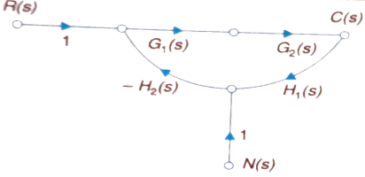
Fig 2. SFG for noise feedback function
 =
= 
For  >>1
>>1
Cn(s) = 
The feedback reduces sensitivity, improves transient response and minimises the effects of disturbance signal in control system.
Control system components
A closed loop control system consists of three basic elements: the feedback element, controller and controlled system. The controller consists of error detector and control elements.

The control element manipulates the actuating signal preferably to different power stage so as to fed to the controlled system. The power stage in control elements is essential for the control signal to drive controlled system. Control elements plays a vital role to get the desired output.
Electrical System
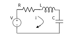
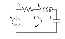
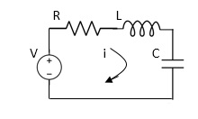
Applying Kirchoff’s voltage Law
V= Ri +Ldi/dt +1/cidt
V= Rdq/dt + L d2q/dt2+q/c
Now By kirchoff’s current low
I= V/R+ 1/L vdt + cdv/dt
But V= dø/dt
I= 1/R dø/dt + 1/L ø+cd2ø/dt2
But v= dø/dt
I= 1/R dø/dt+ 1/L. ø+c d2ø/dt2
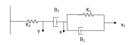
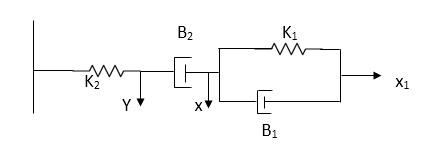
Q.2 For the given mechanical system below draw the analogus system (force. Voltage) & find V0(s)/V1(s)
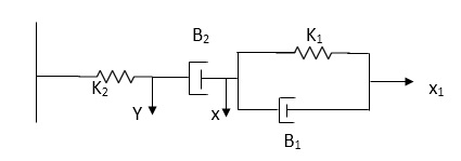
Soln. form the table above we can find the analogus values of system components.
(1) Consider two displacement as two nodes.
(2) If masses are present connect them to reference lines
(3) Connect other elements of system to the nodes
(4) Applying modal analysis to find the system equation.
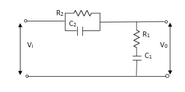
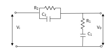
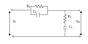
Let Z1 = R2 11 1/c2
=R2*1/c2s/R2+1/c2s
Z1= R2/1+R2c2s
Let Z2 = R1+1/c1s
Z2= 1+R1c1s/c1s
V0(s)/vi(s) = z2/z1+z2
= 1+R1c1s/c1s/R2/1+R2c2s+1+R1c1s/c1s
V0(s)/v0(s) =(c1+R1c1s) (1+R2c2s)/R2c1s+1+sR1c1s2R1R2c1c2
Electromechanical
Armature Controlled dc motor:
In armature controlled motors the time constant is small and hence response is last The efficiency is better than field cannot. The transfer function is calculated below.

Fig.3 Armature controlled d.c servomotor.
Applying kVL in armature circuit
V = Raia+ Ldia/dt +E-----(5)
Where
V= applied voltage
Ra = armature resistance
La = Armature inductance
Ia= Armature current
If= field current
E= Induced emf in armature
T= Torque developed by motor
But E= Kb w
E= kbdø/dt --------(6)
W =angular velocity
Kb= back emf
T= k ia-----(7)
The equation for torque will be
T= Jd2ø/dt2+Bdø/dt --------(8)
Taking Laplace of equation (5), (6), (7), (8)
V(S) – E(S) = I1(s) (Ra+sLa)
E(s) = kb s(s)
T(s) = k Ia (s)
T(S)= (s2J+SB) (S)
T(S) = (SJ+B) s(S)
(S)/v(s) k/(Ra+sla) (Js +B) s+ kkbs ------(a)
The Block diagram representation for above equation (a) is shown below.
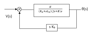
Fig. 4 Block diagram for armature controlled D.C motor
Field controlled D.C. Servomotor:
For field controlled D.C. motor the ratio L/R is large which means time controller for field circuit is large
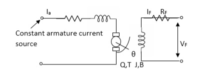
Fig.5 circuit for field controlled D.C motor
Applying KVL in field circuit
Vf= Rf If +Lfd If/dt------(10)
T = k øIa
ø If
ø= kfIf
:. T= kkfIa If
Let k, = KIa
T= k’Kf If --------(11)
Dynamic equation for torque is
T= Jd2/dt2 +Bd/dt ------- (12)
Taking Laplace of above equations
Vf(s) = Rf If (c)+SLf If(s) [Rf+SLf]
If= Vf(S)/Rf+ SLf--------(13)
T(s) =(S) [s2J+SB] --------(14)
T(S) = kkfVf(s)/Rf+SLf------ (15)
From equation (14) and (15) we get
(s)/ vf(s) = kkf/s (sJ+B) (Rf+sLf)
The block diagram representation of above equation (16) is shown in figure below

Fig. 6 Block diagram for field controlled D.C servomotor
Servomechanism is also called servo which is a device usually error sensing device connected as a feedback element to correct the action of a mechanism. Here instead of controlling a device by variable input signal, the device is controlled by feedback signal.
The input signal applied to such systems generate the required output which is compared again to the input signal. If the device achieves its desired output, there will be no longer the logical difference between the two signals. Hence, the primary task of servomechanism is to maintain the output of a system at the desired value in the presence of disturbances.
Servomotors: These motors are used in feedback control system. These are also known as control motors. These motors should have low rotor inertia and high speed of response. The servomotors used in the feedback control systems should have linear control signal and rotor speed.
Types of Servomotors:
(a). A.C. Servomotors
(b). D.C. Servomotors
(a). A.C. Servomotors:
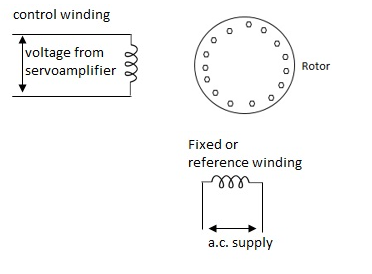
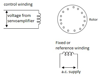
A.C servomotor is a two-phase ac induction motor. There are two windings in this motor, one is fixed or reference winding is supplied with a fixed voltage and frequency from a constant voltage source. Second winding is control winding with variable supply voltage of same frequency as reference winding but having a phase displacement of 900 electrical. A flux is induced due to the phase change which cuts the conducting bars of rotor and causes a time varying current, this current produces a time varying flux and reacts with the stator flux causing the rotor to rotate.
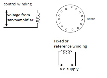
The rotor of A.C. Servomotos are of two types,
(a). Squirrel Cage Rotor
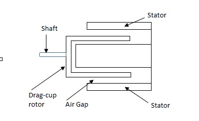
(b). Drag cup type rotor
(a). Squirrel cage rotor: They have high resistance as the rotor is having large length and small diameter. The air gap here is kept small.

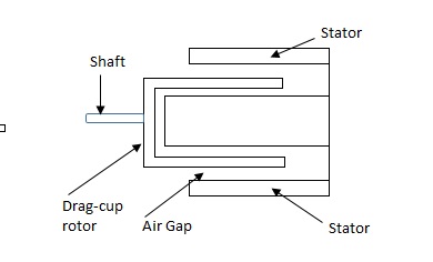
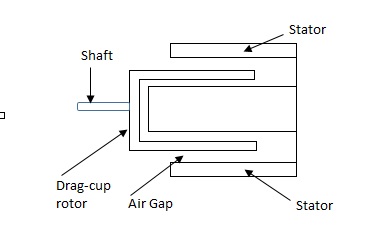
(b). Drag cup type motor: For the drag cup rotor there are two air gaps. For the rotor a cup of non-magnetic conducting material is used. A stationary iron core is placed between the conducting cup to complete the magnetic circuit. The resistance of drag cup type is high and therefore, has high starting torque. Generally aluminium is used for cup.
Torque-speed characteristic:
The torque speed characteristics of the two phase servomotor depends on ratio of reactance to resistance(X/R).
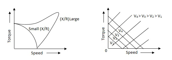
(i). For high ‘R’ and low X, the characteristic is linear and
(ii). For high X and low R, it becomes non-linear.
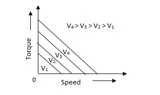
The torque-speed characteristic for various voltage is almost linear.
(b). D.C. Servomotor:
D.C. Servomotor are separately excited or permanent magnet dc servomotors. The armature of D.C. Servomotors is having large resistance and hence torque-speed characteristic is linear.
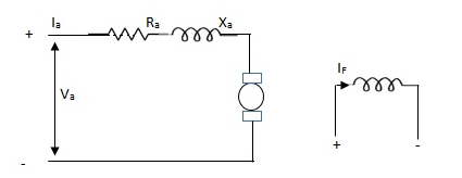
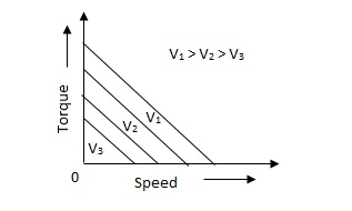
The above graph fig (b), clearly shows that the torque-speed characteristics is a function of control winding voltage as shown below.
T = mw + KVc -- (1)
Where T = Torque developed by motor
w = angular velocity
Vc = control winding voltage
Taking laplace of above equation (1),
T(S) = mS Q(S) + KVc - - (2)
T(S) = JS2Q(S) + FSQ(S) - - (3)
Above equation(3) is the dynamic eqaution with,
J – moment of inertia
F – coefficient of friction of motor
From equation (2) and (3) the block diagram will be,

Q(S)/Vc = K/Js + F + m - - (4)
Comparison between A.C. Servomotor & D.C. Servomotor
| A.C. Servomotor | D.C. Servomotor |
1. | They are less efficient | They are more efficient |
2. | They have low power output | They have high power output |
3. | No noise so has smooth operation | These motors have noisy operation |
4. | They do not have any radio frequency noise | These motors have brushes so produce radio frequency noise |
5. | They are maintenance free because of no brushes and slip rings | For these motors maintenance is required. |
References:
1. Linear System Design D’azzo and Houpis McGraw Hill
2. Control Systems, Principles & Design M. Gopal TMH (Tata McGraw Hill)
3. Control Systems Engineering Samarajit Ghosh Pearson
Unit - 2
Effect of feedback on parameter variation
The feedback systems are having many advantages over the non-feedback system as we have seen earlier. So, some performance parameters can be controlled through this feedback system such as sensitivity, noise etc. Sensitivity is a parameter which forecasts the effectiveness of feedback in reducing the influence of these variations on system performance.
The output of the open loop system is given by
C(s) = G(s)R(s)
Now due to variation in parameters G(s) changes to [G(s)+G(s)]. The output will now become
C(s)+ C(s) = [G(s)+ G(s)] R(s)
C(s) = G(s)R(s)
For closed loop system the output is given as

Now due to variation in parameters it becomes

The above equation shows that if there is variation in parameters then G(s) is reduced by factor of 1+G(s)H(s). The variation in overall transfer function T(s) due to change in G(s) is defined as sensitivity.

When there is small change in G(s) then sensitivity becomes

 : Sensitivity of T w.r.t G
For closed loop system the sensitivity will be

For open loop system

As T=G
The sensitivity of T w.r.t H is given as

The above equation shows that for large values of GH sensitivity of the feedback system w.r.t H approaches to unity.
Key takeaway
For closed loop system the sensitivity w.r.t G is reduced by a factor of (1+GH) as compared to the open loop system.
The feedback helps to control the disturbances as they generate an error signal. The signal flow graph for closed loop system is given by
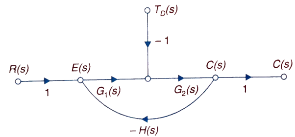
Fig 1 Closed loop system with disturbance signal
 =
= 
Where:
TD(s) = Disturbance signal.
For |G1G2H(s)|>>1 over the range of s
 =
=
The signal flow graph of a system with noise signal N(s) in the feedback path. The gain is given by
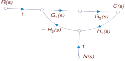
Fig 2. SFG for noise feedback function
 =
= 
For  >>1
>>1
Cn(s) = 
The feedback reduces sensitivity, improves transient response and minimises the effects of disturbance signal in control system.
Control system components
A closed loop control system consists of three basic elements: the feedback element, controller and controlled system. The controller consists of error detector and control elements.

The control element manipulates the actuating signal preferably to different power stage so as to fed to the controlled system. The power stage in control elements is essential for the control signal to drive controlled system. Control elements plays a vital role to get the desired output.
Electrical System
Applying Kirchoff’s voltage Law
V= Ri +Ldi/dt +1/cidt
V= Rdq/dt + L d2q/dt2+q/c
Now By kirchoff’s current low
I= V/R+ 1/L vdt + cdv/dt
But V= dø/dt
I= 1/R dø/dt + 1/L ø+cd2ø/dt2
But v= dø/dt
I= 1/R dø/dt+ 1/L. ø+c d2ø/dt2
Q.2 For the given mechanical system below draw the analogus system (force. Voltage) & find V0(s)/V1(s)
Soln. form the table above we can find the analogus values of system components.
(1) Consider two displacement as two nodes.
(2) If masses are present connect them to reference lines
(3) Connect other elements of system to the nodes
(4) Applying modal analysis to find the system equation.
Let Z1 = R2 11 1/c2
=R2*1/c2s/R2+1/c2s
Z1= R2/1+R2c2s
Let Z2 = R1+1/c1s
Z2= 1+R1c1s/c1s
V0(s)/vi(s) = z2/z1+z2
= 1+R1c1s/c1s/R2/1+R2c2s+1+R1c1s/c1s
V0(s)/v0(s) =(c1+R1c1s) (1+R2c2s)/R2c1s+1+sR1c1s2R1R2c1c2
Electromechanical
Armature Controlled dc motor:
In armature controlled motors the time constant is small and hence response is last The efficiency is better than field cannot. The transfer function is calculated below.

Fig.3 Armature controlled d.c servomotor.
Applying kVL in armature circuit
V = Raia+ Ldia/dt +E-----(5)
Where
V= applied voltage
Ra = armature resistance
La = Armature inductance
Ia= Armature current
If= field current
E= Induced emf in armature
T= Torque developed by motor
But E= Kb w
E= kbdø/dt --------(6)
W =angular velocity
Kb= back emf
T= k ia-----(7)
The equation for torque will be
T= Jd2ø/dt2+Bdø/dt --------(8)
Taking Laplace of equation (5), (6), (7), (8)
V(S) – E(S) = I1(s) (Ra+sLa)
E(s) = kb s(s)
T(s) = k Ia (s)
T(S)= (s2J+SB) (S)
T(S) = (SJ+B) s(S)
(S)/v(s) k/(Ra+sla) (Js +B) s+ kkbs ------(a)
The Block diagram representation for above equation (a) is shown below.
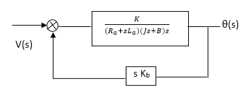
Fig. 4 Block diagram for armature controlled D.C motor
Field controlled D.C. Servomotor:
For field controlled D.C. motor the ratio L/R is large which means time controller for field circuit is large
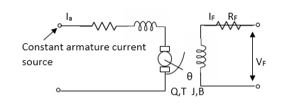
Fig.5 circuit for field controlled D.C motor
Applying KVL in field circuit
Vf= Rf If +Lfd If/dt------(10)
T = k øIa
ø If
ø= kfIf
:. T= kkfIa If
Let k, = KIa
T= k’Kf If --------(11)
Dynamic equation for torque is
T= Jd2/dt2 +Bd/dt ------- (12)
Taking Laplace of above equations
Vf(s) = Rf If (c)+SLf If(s) [Rf+SLf]
If= Vf(S)/Rf+ SLf--------(13)
T(s) =(S) [s2J+SB] --------(14)
T(S) = kkfVf(s)/Rf+SLf------ (15)
From equation (14) and (15) we get
(s)/ vf(s) = kkf/s (sJ+B) (Rf+sLf)
The block diagram representation of above equation (16) is shown in figure below

Fig. 6 Block diagram for field controlled D.C servomotor
Servomechanism is also called servo which is a device usually error sensing device connected as a feedback element to correct the action of a mechanism. Here instead of controlling a device by variable input signal, the device is controlled by feedback signal.
The input signal applied to such systems generate the required output which is compared again to the input signal. If the device achieves its desired output, there will be no longer the logical difference between the two signals. Hence, the primary task of servomechanism is to maintain the output of a system at the desired value in the presence of disturbances.
Servomotors: These motors are used in feedback control system. These are also known as control motors. These motors should have low rotor inertia and high speed of response. The servomotors used in the feedback control systems should have linear control signal and rotor speed.
Types of Servomotors:
(a). A.C. Servomotors
(b). D.C. Servomotors
(a). A.C. Servomotors:
A.C servomotor is a two-phase ac induction motor. There are two windings in this motor, one is fixed or reference winding is supplied with a fixed voltage and frequency from a constant voltage source. Second winding is control winding with variable supply voltage of same frequency as reference winding but having a phase displacement of 900 electrical. A flux is induced due to the phase change which cuts the conducting bars of rotor and causes a time varying current, this current produces a time varying flux and reacts with the stator flux causing the rotor to rotate.
The rotor of A.C. Servomotos are of two types,
(a). Squirrel Cage Rotor
(b). Drag cup type rotor
(a). Squirrel cage rotor: They have high resistance as the rotor is having large length and small diameter. The air gap here is kept small.

(b). Drag cup type motor: For the drag cup rotor there are two air gaps. For the rotor a cup of non-magnetic conducting material is used. A stationary iron core is placed between the conducting cup to complete the magnetic circuit. The resistance of drag cup type is high and therefore, has high starting torque. Generally aluminium is used for cup.
Torque-speed characteristic:
The torque speed characteristics of the two phase servomotor depends on ratio of reactance to resistance(X/R).
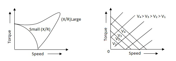
(i). For high ‘R’ and low X, the characteristic is linear and
(ii). For high X and low R, it becomes non-linear.
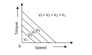
The torque-speed characteristic for various voltage is almost linear.
(b). D.C. Servomotor:
D.C. Servomotor are separately excited or permanent magnet dc servomotors. The armature of D.C. Servomotors is having large resistance and hence torque-speed characteristic is linear.
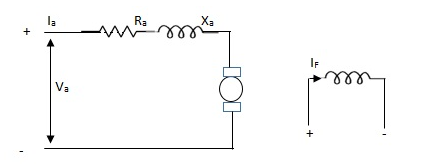
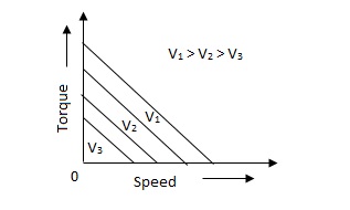
The above graph fig (b), clearly shows that the torque-speed characteristics is a function of control winding voltage as shown below.
T = mw + KVc -- (1)
Where T = Torque developed by motor
w = angular velocity
Vc = control winding voltage
Taking laplace of above equation (1),
T(S) = mS Q(S) + KVc - - (2)
T(S) = JS2Q(S) + FSQ(S) - - (3)
Above equation(3) is the dynamic eqaution with,
J – moment of inertia
F – coefficient of friction of motor
From equation (2) and (3) the block diagram will be,

Q(S)/Vc = K/Js + F + m - - (4)
Comparison between A.C. Servomotor & D.C. Servomotor
| A.C. Servomotor | D.C. Servomotor |
1. | They are less efficient | They are more efficient |
2. | They have low power output | They have high power output |
3. | No noise so has smooth operation | These motors have noisy operation |
4. | They do not have any radio frequency noise | These motors have brushes so produce radio frequency noise |
5. | They are maintenance free because of no brushes and slip rings | For these motors maintenance is required. |
References:
1. Linear System Design D’azzo and Houpis McGraw Hill
2. Control Systems, Principles & Design M. Gopal TMH (Tata McGraw Hill)
3. Control Systems Engineering Samarajit Ghosh Pearson
Unit - 2
Effect of feedback on parameter variation
Unit - 2
Effect of feedback on parameter variation
The feedback systems are having many advantages over the non-feedback system as we have seen earlier. So, some performance parameters can be controlled through this feedback system such as sensitivity, noise etc. Sensitivity is a parameter which forecasts the effectiveness of feedback in reducing the influence of these variations on system performance.
The output of the open loop system is given by
C(s) = G(s)R(s)
Now due to variation in parameters G(s) changes to [G(s)+G(s)]. The output will now become
C(s)+ C(s) = [G(s)+ G(s)] R(s)
C(s) = G(s)R(s)
For closed loop system the output is given as

Now due to variation in parameters it becomes

The above equation shows that if there is variation in parameters then G(s) is reduced by factor of 1+G(s)H(s). The variation in overall transfer function T(s) due to change in G(s) is defined as sensitivity.

When there is small change in G(s) then sensitivity becomes

 : Sensitivity of T w.r.t G
For closed loop system the sensitivity will be

For open loop system

As T=G
The sensitivity of T w.r.t H is given as

The above equation shows that for large values of GH sensitivity of the feedback system w.r.t H approaches to unity.
Key takeaway
For closed loop system the sensitivity w.r.t G is reduced by a factor of (1+GH) as compared to the open loop system.
The feedback helps to control the disturbances as they generate an error signal. The signal flow graph for closed loop system is given by
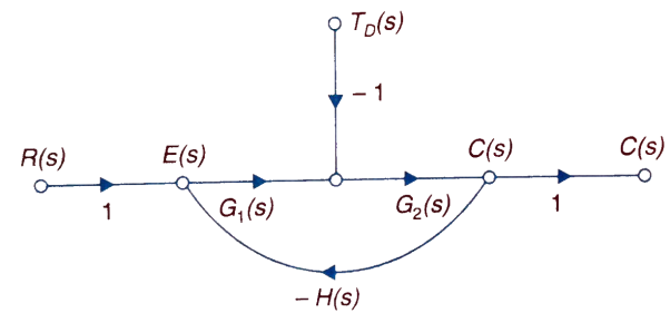
Fig 1 Closed loop system with disturbance signal
 =
= 
Where:
TD(s) = Disturbance signal.
For |G1G2H(s)|>>1 over the range of s
 =
=
The signal flow graph of a system with noise signal N(s) in the feedback path. The gain is given by
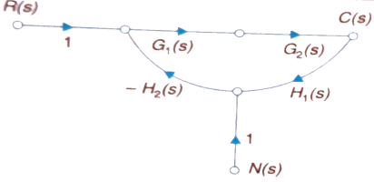
Fig 2. SFG for noise feedback function
 =
= 
For  >>1
>>1
Cn(s) = 
The feedback reduces sensitivity, improves transient response and minimises the effects of disturbance signal in control system.
Control system components
A closed loop control system consists of three basic elements: the feedback element, controller and controlled system. The controller consists of error detector and control elements.

The control element manipulates the actuating signal preferably to different power stage so as to fed to the controlled system. The power stage in control elements is essential for the control signal to drive controlled system. Control elements plays a vital role to get the desired output.
Electrical System
Applying Kirchoff’s voltage Law
V= Ri +Ldi/dt +1/cidt
V= Rdq/dt + L d2q/dt2+q/c
Now By kirchoff’s current low
I= V/R+ 1/L vdt + cdv/dt
But V= dø/dt
I= 1/R dø/dt + 1/L ø+cd2ø/dt2
But v= dø/dt
I= 1/R dø/dt+ 1/L. ø+c d2ø/dt2
Q.2 For the given mechanical system below draw the analogus system (force. Voltage) & find V0(s)/V1(s)
Soln. form the table above we can find the analogus values of system components.
(1) Consider two displacement as two nodes.
(2) If masses are present connect them to reference lines
(3) Connect other elements of system to the nodes
(4) Applying modal analysis to find the system equation.
Let Z1 = R2 11 1/c2
=R2*1/c2s/R2+1/c2s
Z1= R2/1+R2c2s
Let Z2 = R1+1/c1s
Z2= 1+R1c1s/c1s
V0(s)/vi(s) = z2/z1+z2
= 1+R1c1s/c1s/R2/1+R2c2s+1+R1c1s/c1s
V0(s)/v0(s) =(c1+R1c1s) (1+R2c2s)/R2c1s+1+sR1c1s2R1R2c1c2
Electromechanical
Armature Controlled dc motor:
In armature controlled motors the time constant is small and hence response is last The efficiency is better than field cannot. The transfer function is calculated below.

Fig.3 Armature controlled d.c servomotor.
Applying kVL in armature circuit
V = Raia+ Ldia/dt +E-----(5)
Where
V= applied voltage
Ra = armature resistance
La = Armature inductance
Ia= Armature current
If= field current
E= Induced emf in armature
T= Torque developed by motor
But E= Kb w
E= kbdø/dt --------(6)
W =angular velocity
Kb= back emf
T= k ia-----(7)
The equation for torque will be
T= Jd2ø/dt2+Bdø/dt --------(8)
Taking Laplace of equation (5), (6), (7), (8)
V(S) – E(S) = I1(s) (Ra+sLa)
E(s) = kb s(s)
T(s) = k Ia (s)
T(S)= (s2J+SB) (S)
T(S) = (SJ+B) s(S)
(S)/v(s) k/(Ra+sla) (Js +B) s+ kkbs ------(a)
The Block diagram representation for above equation (a) is shown below.
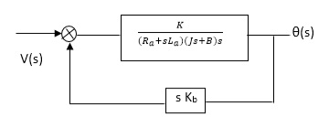
Fig. 4 Block diagram for armature controlled D.C motor
Field controlled D.C. Servomotor:
For field controlled D.C. motor the ratio L/R is large which means time controller for field circuit is large
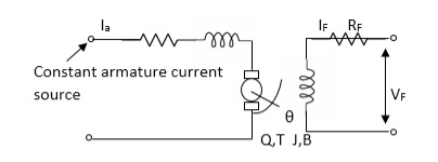
Fig.5 circuit for field controlled D.C motor
Applying KVL in field circuit
Vf= Rf If +Lfd If/dt------(10)
T = k øIa
ø If
ø= kfIf
:. T= kkfIa If
Let k, = KIa
T= k’Kf If --------(11)
Dynamic equation for torque is
T= Jd2/dt2 +Bd/dt ------- (12)
Taking Laplace of above equations
Vf(s) = Rf If (c)+SLf If(s) [Rf+SLf]
If= Vf(S)/Rf+ SLf--------(13)
T(s) =(S) [s2J+SB] --------(14)
T(S) = kkfVf(s)/Rf+SLf------ (15)
From equation (14) and (15) we get
(s)/ vf(s) = kkf/s (sJ+B) (Rf+sLf)
The block diagram representation of above equation (16) is shown in figure below

Fig. 6 Block diagram for field controlled D.C servomotor
Servomechanism is also called servo which is a device usually error sensing device connected as a feedback element to correct the action of a mechanism. Here instead of controlling a device by variable input signal, the device is controlled by feedback signal.
The input signal applied to such systems generate the required output which is compared again to the input signal. If the device achieves its desired output, there will be no longer the logical difference between the two signals. Hence, the primary task of servomechanism is to maintain the output of a system at the desired value in the presence of disturbances.
Servomotors: These motors are used in feedback control system. These are also known as control motors. These motors should have low rotor inertia and high speed of response. The servomotors used in the feedback control systems should have linear control signal and rotor speed.
Types of Servomotors:
(a). A.C. Servomotors
(b). D.C. Servomotors
(a). A.C. Servomotors:
A.C servomotor is a two-phase ac induction motor. There are two windings in this motor, one is fixed or reference winding is supplied with a fixed voltage and frequency from a constant voltage source. Second winding is control winding with variable supply voltage of same frequency as reference winding but having a phase displacement of 900 electrical. A flux is induced due to the phase change which cuts the conducting bars of rotor and causes a time varying current, this current produces a time varying flux and reacts with the stator flux causing the rotor to rotate.
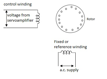
The rotor of A.C. Servomotos are of two types,
(a). Squirrel Cage Rotor
(b). Drag cup type rotor
(a). Squirrel cage rotor: They have high resistance as the rotor is having large length and small diameter. The air gap here is kept small.

(b). Drag cup type motor: For the drag cup rotor there are two air gaps. For the rotor a cup of non-magnetic conducting material is used. A stationary iron core is placed between the conducting cup to complete the magnetic circuit. The resistance of drag cup type is high and therefore, has high starting torque. Generally aluminium is used for cup.
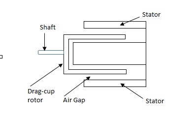
Torque-speed characteristic:
The torque speed characteristics of the two phase servomotor depends on ratio of reactance to resistance(X/R).
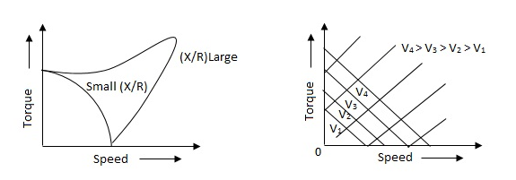
(i). For high ‘R’ and low X, the characteristic is linear and
(ii). For high X and low R, it becomes non-linear.
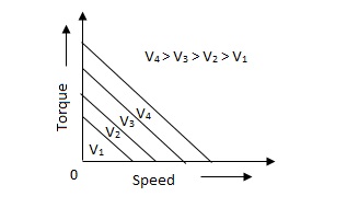
The torque-speed characteristic for various voltage is almost linear.
(b). D.C. Servomotor:
D.C. Servomotor are separately excited or permanent magnet dc servomotors. The armature of D.C. Servomotors is having large resistance and hence torque-speed characteristic is linear.
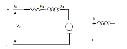
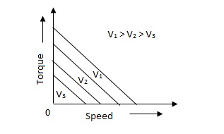
The above graph fig (b), clearly shows that the torque-speed characteristics is a function of control winding voltage as shown below.
T = mw + KVc -- (1)
Where T = Torque developed by motor
w = angular velocity
Vc = control winding voltage
Taking laplace of above equation (1),
T(S) = mS Q(S) + KVc - - (2)
T(S) = JS2Q(S) + FSQ(S) - - (3)
Above equation(3) is the dynamic eqaution with,
J – moment of inertia
F – coefficient of friction of motor
From equation (2) and (3) the block diagram will be,

Q(S)/Vc = K/Js + F + m - - (4)
Comparison between A.C. Servomotor & D.C. Servomotor
| A.C. Servomotor | D.C. Servomotor |
1. | They are less efficient | They are more efficient |
2. | They have low power output | They have high power output |
3. | No noise so has smooth operation | These motors have noisy operation |
4. | They do not have any radio frequency noise | These motors have brushes so produce radio frequency noise |
5. | They are maintenance free because of no brushes and slip rings | For these motors maintenance is required. |
References:
1. Linear System Design D’azzo and Houpis McGraw Hill
2. Control Systems, Principles & Design M. Gopal TMH (Tata McGraw Hill)
3. Control Systems Engineering Samarajit Ghosh Pearson
Unit - 2
Effect of feedback on parameter variation
Unit - 2
Effect of feedback on parameter variation
The feedback systems are having many advantages over the non-feedback system as we have seen earlier. So, some performance parameters can be controlled through this feedback system such as sensitivity, noise etc. Sensitivity is a parameter which forecasts the effectiveness of feedback in reducing the influence of these variations on system performance.
The output of the open loop system is given by
C(s) = G(s)R(s)
Now due to variation in parameters G(s) changes to [G(s)+G(s)]. The output will now become
C(s)+ C(s) = [G(s)+ G(s)] R(s)
C(s) = G(s)R(s)
For closed loop system the output is given as

Now due to variation in parameters it becomes

The above equation shows that if there is variation in parameters then G(s) is reduced by factor of 1+G(s)H(s). The variation in overall transfer function T(s) due to change in G(s) is defined as sensitivity.

When there is small change in G(s) then sensitivity becomes

 : Sensitivity of T w.r.t G
For closed loop system the sensitivity will be

For open loop system

As T=G
The sensitivity of T w.r.t H is given as

The above equation shows that for large values of GH sensitivity of the feedback system w.r.t H approaches to unity.
Key takeaway
For closed loop system the sensitivity w.r.t G is reduced by a factor of (1+GH) as compared to the open loop system.
The feedback helps to control the disturbances as they generate an error signal. The signal flow graph for closed loop system is given by
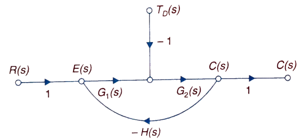
Fig 1 Closed loop system with disturbance signal
 =
= 
Where:
TD(s) = Disturbance signal.
For |G1G2H(s)|>>1 over the range of s
 =
=
The signal flow graph of a system with noise signal N(s) in the feedback path. The gain is given by
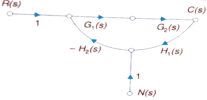
Fig 2. SFG for noise feedback function
 =
= 
For  >>1
>>1
Cn(s) = 
The feedback reduces sensitivity, improves transient response and minimises the effects of disturbance signal in control system.
Control system components
A closed loop control system consists of three basic elements: the feedback element, controller and controlled system. The controller consists of error detector and control elements.

The control element manipulates the actuating signal preferably to different power stage so as to fed to the controlled system. The power stage in control elements is essential for the control signal to drive controlled system. Control elements plays a vital role to get the desired output.
Electrical System
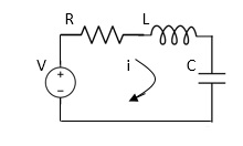
Applying Kirchoff’s voltage Law
V= Ri +Ldi/dt +1/cidt
V= Rdq/dt + L d2q/dt2+q/c
Now By kirchoff’s current low
I= V/R+ 1/L vdt + cdv/dt
But V= dø/dt
I= 1/R dø/dt + 1/L ø+cd2ø/dt2
But v= dø/dt
I= 1/R dø/dt+ 1/L. ø+c d2ø/dt2
Q.2 For the given mechanical system below draw the analogus system (force. Voltage) & find V0(s)/V1(s)
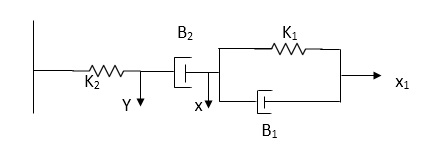
Soln. form the table above we can find the analogus values of system components.
(1) Consider two displacement as two nodes.
(2) If masses are present connect them to reference lines
(3) Connect other elements of system to the nodes
(4) Applying modal analysis to find the system equation.
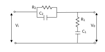
Let Z1 = R2 11 1/c2
=R2*1/c2s/R2+1/c2s
Z1= R2/1+R2c2s
Let Z2 = R1+1/c1s
Z2= 1+R1c1s/c1s
V0(s)/vi(s) = z2/z1+z2
= 1+R1c1s/c1s/R2/1+R2c2s+1+R1c1s/c1s
V0(s)/v0(s) =(c1+R1c1s) (1+R2c2s)/R2c1s+1+sR1c1s2R1R2c1c2
Electromechanical
Armature Controlled dc motor:
In armature controlled motors the time constant is small and hence response is last The efficiency is better than field cannot. The transfer function is calculated below.

Fig.3 Armature controlled d.c servomotor.
Applying kVL in armature circuit
V = Raia+ Ldia/dt +E-----(5)
Where
V= applied voltage
Ra = armature resistance
La = Armature inductance
Ia= Armature current
If= field current
E= Induced emf in armature
T= Torque developed by motor
But E= Kb w
E= kbdø/dt --------(6)
W =angular velocity
Kb= back emf
T= k ia-----(7)
The equation for torque will be
T= Jd2ø/dt2+Bdø/dt --------(8)
Taking Laplace of equation (5), (6), (7), (8)
V(S) – E(S) = I1(s) (Ra+sLa)
E(s) = kb s(s)
T(s) = k Ia (s)
T(S)= (s2J+SB) (S)
T(S) = (SJ+B) s(S)
(S)/v(s) k/(Ra+sla) (Js +B) s+ kkbs ------(a)
The Block diagram representation for above equation (a) is shown below.
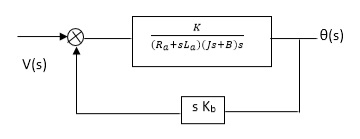
Fig. 4 Block diagram for armature controlled D.C motor
Field controlled D.C. Servomotor:
For field controlled D.C. motor the ratio L/R is large which means time controller for field circuit is large
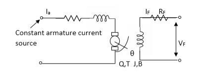
Fig.5 circuit for field controlled D.C motor
Applying KVL in field circuit
Vf= Rf If +Lfd If/dt------(10)
T = k øIa
ø If
ø= kfIf
:. T= kkfIa If
Let k, = KIa
T= k’Kf If --------(11)
Dynamic equation for torque is
T= Jd2/dt2 +Bd/dt ------- (12)
Taking Laplace of above equations
Vf(s) = Rf If (c)+SLf If(s) [Rf+SLf]
If= Vf(S)/Rf+ SLf--------(13)
T(s) =(S) [s2J+SB] --------(14)
T(S) = kkfVf(s)/Rf+SLf------ (15)
From equation (14) and (15) we get
(s)/ vf(s) = kkf/s (sJ+B) (Rf+sLf)
The block diagram representation of above equation (16) is shown in figure below

Fig. 6 Block diagram for field controlled D.C servomotor
Servomechanism is also called servo which is a device usually error sensing device connected as a feedback element to correct the action of a mechanism. Here instead of controlling a device by variable input signal, the device is controlled by feedback signal.
The input signal applied to such systems generate the required output which is compared again to the input signal. If the device achieves its desired output, there will be no longer the logical difference between the two signals. Hence, the primary task of servomechanism is to maintain the output of a system at the desired value in the presence of disturbances.
Servomotors: These motors are used in feedback control system. These are also known as control motors. These motors should have low rotor inertia and high speed of response. The servomotors used in the feedback control systems should have linear control signal and rotor speed.
Types of Servomotors:
(a). A.C. Servomotors
(b). D.C. Servomotors
(a). A.C. Servomotors:
A.C servomotor is a two-phase ac induction motor. There are two windings in this motor, one is fixed or reference winding is supplied with a fixed voltage and frequency from a constant voltage source. Second winding is control winding with variable supply voltage of same frequency as reference winding but having a phase displacement of 900 electrical. A flux is induced due to the phase change which cuts the conducting bars of rotor and causes a time varying current, this current produces a time varying flux and reacts with the stator flux causing the rotor to rotate.
The rotor of A.C. Servomotos are of two types,
(a). Squirrel Cage Rotor
(b). Drag cup type rotor
(a). Squirrel cage rotor: They have high resistance as the rotor is having large length and small diameter. The air gap here is kept small.

(b). Drag cup type motor: For the drag cup rotor there are two air gaps. For the rotor a cup of non-magnetic conducting material is used. A stationary iron core is placed between the conducting cup to complete the magnetic circuit. The resistance of drag cup type is high and therefore, has high starting torque. Generally aluminium is used for cup.
Torque-speed characteristic:
The torque speed characteristics of the two phase servomotor depends on ratio of reactance to resistance(X/R).
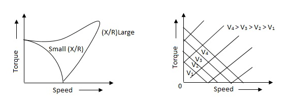
(i). For high ‘R’ and low X, the characteristic is linear and
(ii). For high X and low R, it becomes non-linear.
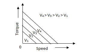
The torque-speed characteristic for various voltage is almost linear.
(b). D.C. Servomotor:
D.C. Servomotor are separately excited or permanent magnet dc servomotors. The armature of D.C. Servomotors is having large resistance and hence torque-speed characteristic is linear.
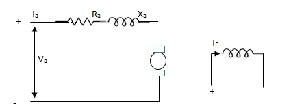
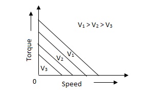
The above graph fig (b), clearly shows that the torque-speed characteristics is a function of control winding voltage as shown below.
T = mw + KVc -- (1)
Where T = Torque developed by motor
w = angular velocity
Vc = control winding voltage
Taking laplace of above equation (1),
T(S) = mS Q(S) + KVc - - (2)
T(S) = JS2Q(S) + FSQ(S) - - (3)
Above equation(3) is the dynamic eqaution with,
J – moment of inertia
F – coefficient of friction of motor
From equation (2) and (3) the block diagram will be,

Q(S)/Vc = K/Js + F + m - - (4)
Comparison between A.C. Servomotor & D.C. Servomotor
| A.C. Servomotor | D.C. Servomotor |
1. | They are less efficient | They are more efficient |
2. | They have low power output | They have high power output |
3. | No noise so has smooth operation | These motors have noisy operation |
4. | They do not have any radio frequency noise | These motors have brushes so produce radio frequency noise |
5. | They are maintenance free because of no brushes and slip rings | For these motors maintenance is required. |
References:
1. Linear System Design D’azzo and Houpis McGraw Hill
2. Control Systems, Principles & Design M. Gopal TMH (Tata McGraw Hill)
3. Control Systems Engineering Samarajit Ghosh Pearson