Unit - 4
Stability of control systems
Concept of Stability:
A stable system always gives bounded output for bounded input and the system is known as BIBO stable
A linear time invariant (LTI) system is stable if,
The system is BIBO stable
In absence of the input the output tends towards zero
For system;
1.


For R(s) = 1
C(S) = 
R (t) =  (t) C (t) = t

Bounded Unbounded
So, system unstable.
2.

[R(s) = 1]
 =
= 
C(t) = e-10tC(t)
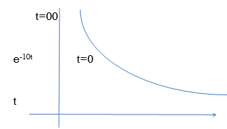
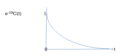
Fig. BIBO stable
Effect of location of Poles on stability
A) Real and negative G(s)= 
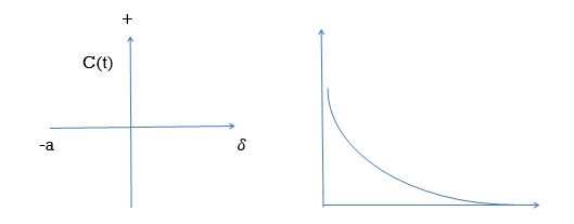
Fig. Output for G(s)= 
Stable
B) Poles on right half of S- plane
G(s) = 

Unstable Unbounded Output
Fig. Input and Output for G(s) = 
(C)Poles at origin
G(s)=
Marginally stable

Fig. Input and output for G(s)=
4) Complex poles on left half of S-plane
S1, S2= -α ± iw
 =
= 
C(t) = k e- αt Coswt

Fig. Pole location and output for C(t) = k e- αt Cos wt
At t - ∞ C(t) – 0 so, system stable
5) Complex poles on right half of S-plane
S1,S2 = α ± iw.
C(t) = k eαt COS wt.
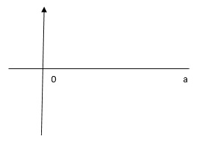
C(t) increases exponentially with t ∞
So, unstable.
6) Poles on iw axis:
S1, S2 = ± iw.
C(t) = k COS wt.
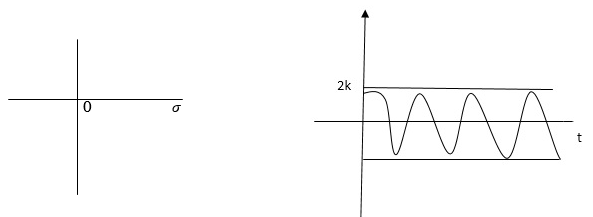
Fig. Output response of C(t) = k COS wt.
The system is marginally stable than sustained oscillations.
Key takeaway
Consider a system with characteristic equation
aoSm + a1 Sm-1 ……………..am=0.
1) All the coefficients of above equation should have same sign.
2) There should be no missing term.
The nth order differential equation of LTI discrete data system can be represented as
y(k+n) +an-1y(k+n-1) +an-2y(k+n-2) +…. +a1y(k+1) +a0y(k)=bmx(k+m) +bm-1x(k+m-1) +…. +b0x(k)
x(k) and y(k) are the inputs and outputs of the system respectively. The z-transform can be obtained as
H(z)=Y(z)/X(z)
 (i)
(i)
The characteristic equation is obtained by equating the denominator to zero

Que) G(s)=2/s(s+2). Find the characteristic equation for the transfer function H(z) with unity feedback. Let T=0.2sec?
Sol:

Finding


(T=0.2sec)
Hence, the characteristic equation will be
1+G(z)H(z)=0
But there is unity feedback so
1+G(z)=0

z2-1.34z+0.67=0
The required characteristic equation is z2-1.34z+0.67=0
It states that the system is stable if and only if all the elements is the first column have the same algebraic sign. If all elements are not of the same sign then the number of sign changes of elements in first column equals the number of roots of the characteristic equation in the right half of S-plane.
Consider the following characteristic equation:
a0 Sn + a1 Sn-1 ………….an = 0 where a0,a1,,,,,,,,,,,,,,,,,,,,an have same sign and are non-zero.
Step1 Arrange coefficients in rows
Row1 ao a2 a4
Row2 a1 a3 a5
Step2 Find third row from above two rows
Row1 a0 a2 a4
Row2 a1 a3 a5
Row3 a1 a3 a5
a1 =  =
= 
a3 =  =
= 
Continue the same procedure to find new rows.
Q1) For the given polynomials below determine the stability of the system
S4+2S3+3S2+4S+5=0
Sol: Arranging Coefficient in Rows.
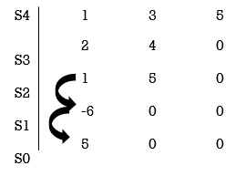
For row S2first term
S2 =  = 1
= 1
For row S2 Second term
S2 =  = 5
= 5
For row S1:
S1 =  = -6
= -6
For row S0
S0 =  = 5
= 5
As there are two sign change in the first column, So there are two roots or right half of S-plane making system unstable.
Q2. Using Routh criterion determine the stability of the system with characteristic equation S4+8S3+18S2+16S+S = 0
Sol:
Arrange in rows.
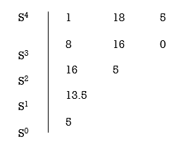
For row S2 first element
S1 =  = 16
= 16
Second terms =  = 5
= 5
For S1
First element =  = 13.5
For S0
First element =  = 5
= 5
As there is no sign change for first column so all roots are is left half of S-plane and hence system is stable.
(I) When first element of any row is zero.
In this case the zero is replaced by a very small positive number E and rest of the array is evaluated.
Eg. Consider the following equation
S3+S+2 = 0
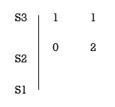
Replacing 0 by E
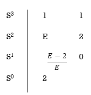
Now when E  0, values in column 1 becomes
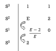
Two sign changes hence two roots on right side of S-plans
(II)When any one row is having all its terms zero.
When array one row of Routh Hurwitz table is zero, it shown that the X is attests one pair of roots which lies radially opposite to each other in this case the array can be completed by auxiliary polynomial. It is the polynomial row first above row zero.
Eg. Consider following example
S3 + 5S2 + 6S + 30
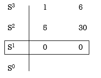
For forming auxiliary equation, selecting row first above row hang all terms zero.
A(s) = 5S2 e30
 = 10s e0.
Again forming Routh array
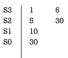
No sign change in column one the roots of Auxiliary equation A(s)=5s2+ 30-0
5s2+30 = 0
S2 α 6= 0
S = ± j 
Both lie on imaginary axis so system is marginally stable.
Q3. Determine the stability of the system represent by following characteristic equations using Routh criterion
1) S4 + 3s3 + 8s2 + 4s +3 = 0
2) S4 + 9s3 + 4S2 – 36s -32 = 0
Sol:
1) S4+3s3+8s2+4s+3=0
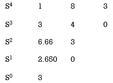
No sign change in first column to no rows on right half of S-plane system stable.
2) S4 + 9s3 + 4S2 – 36s -32 = 0
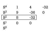
Special case II of Routh Hurwitz criterion forming auxiliary equation
A1 (s) = 8S2 – 32 = 0
 = 16S – 0 =0
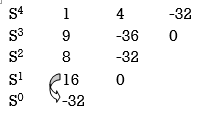
One sign change so, one root lies on right half S-plane hence system is unstable.
Q4. For using feedback open loop transfer function G(s) = 
Find range of k for stability
Sol:
Find characteristics equation
CE = 1+G (s) H(s) = 0
H(s) =1 using feedback
CE = 1+ G(s)
1+  = 0
= 0
S(S+1)(S+3)(S+4)+k = 0
(S2+5)(S2+7Sα12)αK = 0
S4α7S3α1252+S3α7S2α125αK = 0
S4+8S3α19S2+125+k = 0
By Routh Hurwitz Criterion
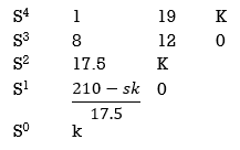
For system to be stable the range of K is 0< K < .
.
Q5. The characteristic equation for certain feedback control system is given. Find range of K for system to be stable. S4+4S3α12S2+36SαK = 0
Sol:
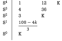
S4+4S3α12S2+36SαK = 0
For stability K>0
 > 0
> 0
K < 27
Range of K will be 0 < K < 27
Relative Stability:
Routh stability criterion deals about absolute stability of any closed loop system. For relative stability we need to shift the S-plane and the apply the Routh criterion.
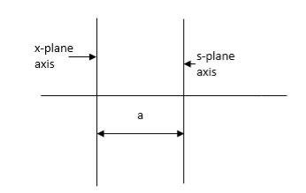
Fig. Location of Pole for relative stability
The above fig shows the characteristic equation is modified by shifting the origin of S-plane to S1= -
S = Z-S1
After substituting new valve of S =(Z-S1) applying Routh stability criterion, the number of sign changes in first column is the number of roots on right half of S-plane
Q6. Check if all roots of equation
S3+6S2+25S+38 = 0, have real poll more negative than -1.
Soln:
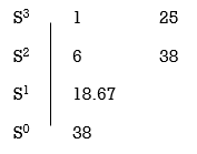
No sign change in first column, hence all roots are in left half of S-plane.
Replacing S = Z-1. In above equation
(Z-1)3+6(Z-1)2+25(Z-1)+38 = 0
Z3+ Z23+16Z+18=0
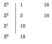
No sign change in first column roots lie on left half of Z-plane hence all roots of original equation in S-domain lie to left half 0f S = -1
Key takeaway
Special Cases of Routh Hurwitz Criterions
(I) When first element of any row is zero.
In this case the zero is replaced by a very small positive number E and rest of the array is evaluated.
(II) When any one row is having all its terms zero.
When array one row of Routh Hurwitz table is zero, it shown that the X is attests one pair of roots which lies radially opposite to each other in this case the array can be completed by auxiliary polynomial. It is the polynomial row first above row zero.
In a system, stability implies small changes in the input do not result in large changes in the output. A linear time−invariant system is called to be stable, if the output eventually comes back to its equilibrium after disturbances. A linear time invariant system is called as unstable if the output continues to oscillate or increases unbounded from equilibrium state under the influence of disturbance.
For nonlinear system, there may or may not be infinite equilibrium states. Hence to define the concept of stability for such multiple existence equilibrium states is very difficult.
If the impulse response of a system is absolutely integrable, i.e.

Then the system is said to be stable. The nature of h(t) depends on poles of the transfer function H(s) which are the roots of characteristic equation.
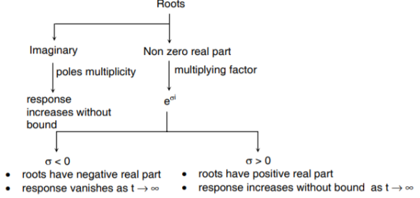
Following conclusions can be drawn:
- If roots have negative real part → impulse response is bounded. System stable.
- If roots have positive real part → system unstable
- If roots are repeated (more than 2) on imaginary axis → system is unstable.
- If roots are non-repeated (one or more) on imaginary axis → system is marginally stable. As h(t) is bounded but ∫h(t) dt is not finite. (oscillatory)
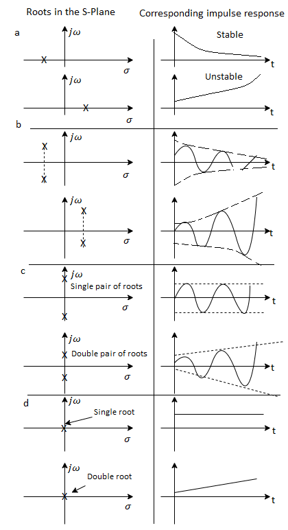
Closed loop poles in the right half s−plane are not permissible as the system becomes unstable.
The root locus is graphical produce for determining the stability of a control system which is determined by the location of the poles. The poles are nothing but the roots of the characteristic equation.
Properties of Root Locus
- It is symmetrical to the real axis.
- Number of branches of root locus is equal to number of max (poles or zero).
- Starting point (k=0) End point(k—>∞)
(open loop poles) (open loop zeros)
4. A point on the real axis lies on the root locus if number of open loop poles or zero to the right side of that point is odd in number.
5. Value of K anywhere on the root locus is given as
K = 
6. I) If poles > zeros then (Þ-z) branches will terminate at ∞ (where k=∞)
II) If Z > P, then (Z-P) branches will start from ∞ (K = 0)
7. When P>Z, (P-Z) branches will terminate at ∞ (open loop zeros). But by which path. So the path is shown by asymptotes and this asymptotes is given by
Asymptote =  q = o,1,2……(P-Z-1)
8. There asymptotes intersect the real axis at a single point and this point is known as centroid.
Centroid = 
9. Break away and break in point when root locus lie between two poles its called break in point.
Centroid and Breakaway points are not same
Differentials the characteristic equation and equate to zero 
10. Angle of arrival and angle of departure this print is used when the roots are complex.
Angle of departure - for complex poles
Angle of arrival – for complex zero.

11. Intersection of root locus with imaginary axis can be calculated by Routh Hurwitz. By calculating valve of k at intersection point (we can comment about system stability) so by knowing values of k at intersection point (imaginary axis) the valve of s at that point can also be calculated.
Stable: If the root low (all the branches) lies within the left side of the S-plane.
Conditionally Stable: If some part of the root locus lies on the left half and the same
The part on the right of the S-plane then is conditionally stable.
Unstable: If the root locus lies completely on the right side of the S-plane then it is unstable.
The values of S which satisfy both the angle and magnitude conditions are the roots of the characteristic equation.
Angle condition:
LG(S)H(S) = +-1800(2 KH) (K = 1,2,3,--)
If the angle is an odd multiple of 1800 it satisfies the above condition.
Magnitude condition:
| G(S)H(S) = 1 | at any point on the root locus. The magnitude condition can be applied only if the angle condition is satisfied.
Design aspects of Root Locus
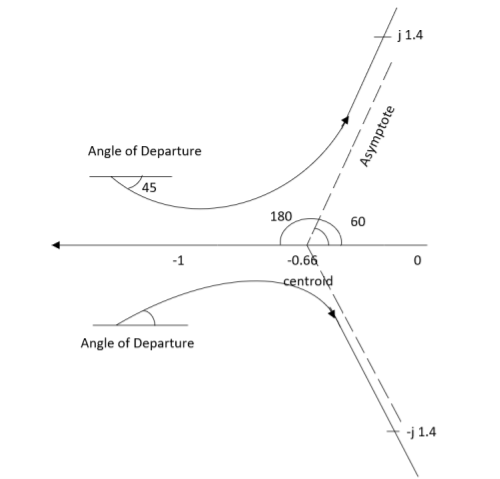
Q1. Sketch the root locus for given open loop transfer function G(S) = .
.
Sol: 1) G(s) = 
Number of Zeros = 0
Number of polls S = (0, -1+j, -1-j) = (3).
1) Number of Branches = max (P, Z) = max (3, 0) = 3.
2) As there are no zeros in the system so, all branches terminate at infinity.
3) As P>Z, branches terminate at infinity through the path shown by asymptotes
Asymptote =  × 180° q = 0, 1, 2………..(p-z-1)
P=3, Z=0.
q= 0, 1, 2.
For q=0
Asymptote = 1/3 × 180° = 60°
For q=1
Asymptote =  × 180°
= 180°
For q=2
Asymptote =  × 180° = 300°
Asymptotes = 60°,180°,300°.
4) Asymptote intersects real axis at centroid
Centroid =
= 
Centroid = -0.66
5) As poles are complex so angle of departure
øD = (2q+1)×180°+ø
ø = ∠Z –∠P.
Calculating ø for S=0
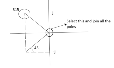
Join all the other poles with S=0
ø = ∠Z –∠P.
= 0-(315°+45°)
= -360°
ØD = (2q + 1)180 + ø.
= 180° - 360°
ØD = -180° (for q=0)
= 180° (for q=1)
=540° (for q=2)
Calculation ØD for pole at (-1+j)
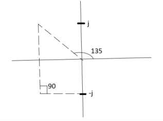
ø = ∠Z –∠P.
= 0 –(135°+90°)
= -225°
ØD = (2q+1) 180°+ø.
= 180-225°
= -45°
ØD = -45° (for q = 0)
= 315° (for q = 1)
= 675° (for q =2)
6) The crossing point on the imaginary axis can be calculated by Routh Hurwitz the characteristic equation is.
1+G(s) H (s) = 0
1+
S (S2+2s+2)+k = 0
S3+2s2+2s+K = 0
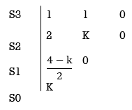
For stability  >0. And K > 0.
0<K<2.
So, when K=2 root locus crosses imaginary axis
S3 + 2S2 + 2S + 2 =0
For k
Sn-1 = 0 n: no. Of intersection
S2-1 = 0 at imaginary axis
S1 = 0
 = 0
= 0
K<4
For Sn = 0 for valve of S at that K
S2 = 0
2S2 + K = 0
2S2 + 2 = 0
2(S2 +1) = 0
32 = -2
S = ± j 
The root locus plot is shown in figure below.
Q2. Sketch the root locus plot for the following open loop transfer function
G(s) = 
Sol:
- Number of zero = 0, number of poles = 3
2. As P>Z, branches will terminates at infinity
3. There are no zeros so all branches will terminate at infinity.
4. The path for the branches is shown by asymptote
Asymptote =  ×180°. q=0,1,………p-z-1
P=3, Z=0
q= 0,1,2.
For q = 0
Asymptote =  × 180° = 60.
For q=1
Asymptote =  × 180° = 180°
For q=2
Asymptote =  × 180° = 300°
5. Asymptote intersect real axis at centroid
Centroid = 
=  = -1
= -1
6. As root locus lies between poles S= 0, and S= -1
So, calculating breakaway point.
 = 0
= 0
The characteristic equation is
1+ G(s) H (s) = 0.
1+  = 0
= 0
K = -(S3+3S2+2s)
 = 3S2+6s+2 = 0
3s2+6s+2 = 0
S = -0.423, -1.577.
So, breakaway point is at S=-0.423
Because root locus is between S= 0 and S= -1
7. The intersection of root locus with imaginary axis is given by Routh criterion.
Characteristics equation is
S3+3S3+2s+K = 0

For k
Sn-1= 0 n: no. Of intersection with imaginary axis
n=2
S1 = 0
 = 0
= 0
K < 6Valve of S at the above valve of K
Sn = 0
S2 = 0
3S2 + K =0
3S2 +6 = 0
S2 + 2 = 0
S = ±  j
j
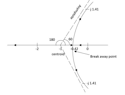
The root locus plot is shown in fig.
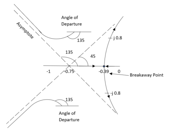
Q3. Plot the root locus for the given open loop transfer function
G(s) = 
Sol:
- Number of zeros = 0 number of poles = 4
P = (S=0,-1,-1+j,-1-j) = 4
2. As P>Z all the branches will terminated at infinity.
3. As no zeros so all branches terminate at infinity.
4. The path for branches is shown by asymptote.
Asymptote =  q = 0,1,…..(Þ-z-1)
q=0,1,2,3. (P-Z = 4-0)
For q=0
Asymptote =  ×180° =45°
For q=1
Asymptote =  ×180° =135°
For q=2
Asymptote =  ×180° =225°
For q=3
Asymptote =  ×180° =315°
5. Asymptote intersects real axis at unmarried
Centroid = 
Centroid =  =
=  = -0.75
6) As poles are complex so angle of departure is
ØD = (2q+1) ×180 + ø ø = ∠Z –∠P.
a) Calculating Ø for S=0
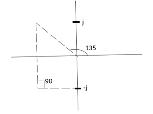
ø = ∠Z –∠P.
= 0 –[315° + 45°]
Ø = -360°
For q = 0
ØD = (2q+1) 180° + Ø
= 180 - 360°
ØD = -180°
b) Calculating Ø for S=-1+j
ø = ∠Z –∠P.
= 0-[135° + 90° + 90°]
Ø = -315°
For q=0
ØD= (2q+1) 180° +Ø
= 180° -315°
ØD = -135°
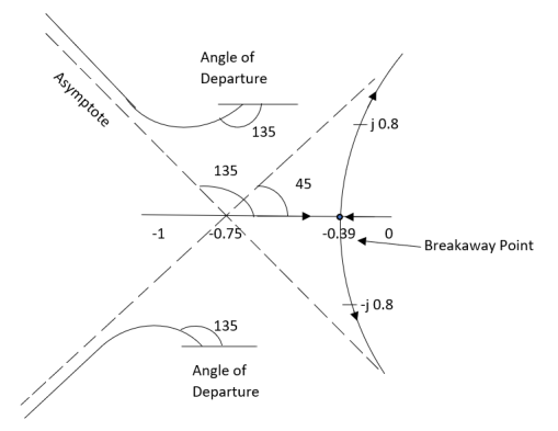
ØD for S=1+j will be ØD = 45°
7) As the root locus lie between S=0 and S=-1
So, the breakaway point is calculated

1+ G(s)H(s) = 0
1+  = 0
= 0
(S2+S)(S2 +2S+2) + K =0
K = -[S4+S3+2s3+2s2+2s2+2s]
 = 4S3+9S2+8S+2=0
S = -0.39, -0.93, -0.93.
The breakaway point is at S = -0.39 as root locus exists between S= 0 and S=-1
8) Intersection of root locus with imaginary axis is given by Routh Hurwitz
I + G(s) H(s) = 0
K+S4+3S3+4S2+2S=0
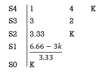
For system to be stable
 >0
>0
6.66>3K
0<K<2.22.
For K = 2.22
3.3352+K =0
3.3352+ 2.22 = 0
S2 = -0.66
S = ± j 0.816.
The root locus plot is shown in figure below.
Q4. Plot the root locus for open loop system
G(s) = 
Sol:
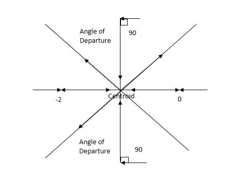
1) Number of zero = 0 number of poles = 4 located at S=0, -2, -1+j, -1-j.
2) As no zeros are present so all branches terminated at infinity.
3) As P>Z, the path for branches is shown by asymptote
Asymptote = 
q = 0,1,2……p-z-1
For q = 0
Asymptote = 45°
q=1
Asymptote = 135°
q=2
Asymptote = 225°
q=3
Asymptote = 315°
4) Asymptote intersects real axis at centroid.
Centroid = 
= 
Centroid = -1.
5) As poles are complex so angle of departure is
ØD=(2q+1)180° + Ø
ø = ∠Z –∠P
= 0-[135°+45°+90°]
= 180°- 270°
ØD = -90°
6) As root locus lies between two poles so calculating point. The characteristic equation is
1+ G(s)H(s) = 0
1+ = 0.
= 0.
K = -[S4+2S3+2S2+2S3+4S2+4S]
K = -[S4+4S3+6S2+4S]
 = 0
= 0
 = 4s3+12s2+12s+4=0
S = -1
So, breakaway point is at S = -1
7) Intersection of root locus with imaginary axis is given by Routh Hurwitz.
S4+4S3+6S2+4s+K = 0
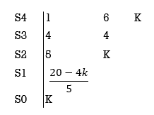
 ≤ 0
≤ 0
K≤5.
For K=5 valve of S will be.
5S2+K = 0
5S2+5 = 0
S2 +1 = 0
S2 = -1
S = ±j.
The root locus is shown in figure below.
Q5. Plot the root locus for open loop transfer function G(s) = 
Sol:
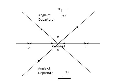
- Number of zeros = 0. Number of poles = 4 located at S=0, -3, -1+j, -1-j.
2. As no. Zero so all branches terminate at infinity.
3. The asymptote shows the both to the branches terminating at infinity.
Asymptote =  q=0,1,….(p-z).
For q = 0
Asymptote = 45
For q = 1
Asymptote = 135
For q = 2
Asymptote = 225
For q = 3
Asymptote = 315
4. The asymptote intersects real axis at centroid.
Centroid = ∑Real part of poles - ∑Real part of zero / P – Z
= [-3-1-1] – 0 / 4 – 0
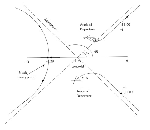
Centroid = -1.25
5. As poles are complex so angle of departure
φD = (29 + 1)180 + φ
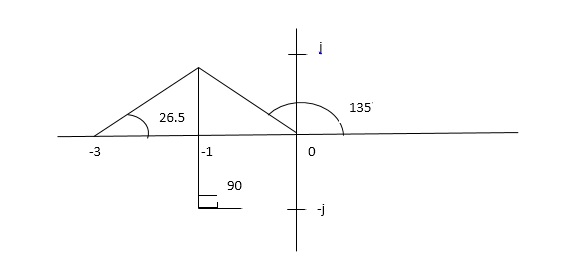
ø = ∠Z –∠P.
= 0 – [ 135 + 26.5 + 90 ]
= -251.56
For q = 0
φD = (29 + 1)180 + φ
= 180 – 215.5
φD = - 71.56
6. Break away point dk / ds = 0 is at S = -2.28.
7. The intersection of root locus on imaginary axis is given by Routh Hurwitz.
1 + G(S)H(S) = 0
K + S4 + 3S3 + 2S3 + 6S2 + 2S2 + 6S = 0
S418K
S356
S234/5K
S140.8 – 5K/6.8
K ≤ 8.16
For K = 8.16 value of S will be
6.8 S2 + K = 0
6.8 S2 + 8.16 = 0
S2 = - 1.2
S = ± j1.09
The plot is shown in figure below.
Q.6. Sketch the root locus for open loop transfer function.
G(S) = K(S + 6)/S(S + 4)
Sol:
- Number of zeros = 1(S = -6)
Number of poles = 2(S = 0, -4)
2. As P > Z one branch will terminate at infinity and the other at S = -6.
3. For Break away and breaking point
1 + G(S)H(S) = 0
1 + K(S + 6)/S(S + 4) = 0
Dk/ds = 0
S2 + 12S + 24 = 0
S = -9.5, -2.5
Breakaway point is at -2.5 and Break in point is at -9.5.
4. Root locus will be in the form of a circle. So finding the centre and radius. Let S = + jw.
G( + jw) = K( + jw + 6)/( + jw)( + jw + 4 ) = +- π
Tan-1 w/ + 6 - tan-1 w/ – tan-1 w / + 4 = - π
Taking tan of both sides.
w/ + w/ + 4 / 1 – w/ w/ + 4 = tan π + w / + 6 / 1 - tan π w/ + 6
w/ + w/ + 4 = w/ + 6[ 1 – w2 / ( + 4) ]
(2 + 4)( + 6) = (2 + 4 – w2)
2 2 + 12 + 4 + 24 = 2 + 4 – w2
22 + 12 + 24 = 2 – w2
2 + 12 – w2 + 24 = 0
Adding 36 on both sides
( + 6)2 + (w + 0)2 = 12
The above equation shows circle with radius 3.46 and center(-6, 0) the plot is shown in figure below.
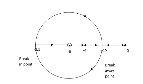
Fig. Root locus for G(S) = K (S + 6)/S (S + 4)
Effect of Addition of Poles:
1) The root locus is shifted towards imaginary axis.
2) The system becomes oscillatory.
3) The stability of system decreases.
4) The settling time increases.
5) The range of k reduces.
Effect of addition of zeros
1) The root locus shifts away from imaginary axis.
2) Stability of system increases.
3) The settling time decreases.
4) The gain margin increases.
5) The system becomes less oscillatory.
References:
1. Automatic Control system (II Edition) – Benjamin C, Kuo, PHI
2. Modern Control System, Drof, Bishop, Wesly Publication
3. Control system Engineering, S.K. Bhattacharya, Pearson Education.