Unit - 1
Amplitude Modulation
Modulation
- It is a process through which audio, video, image or text information is added to an electrical or optical carrier signal that is to be transmitted over a telecommunication or electronic medium.
- It enables the transfer of information on an electrical signal to a receiver that is capable of demodulating the signal to extract the blended information.
- It is primarily used in telecommunication technologies that require the transmission of data via electrical signals.
- It is considered the backbone of data communication as it enables the use of electrical and optical signals as information carriers.
- This is done by altering the periodic waveform or the carrier.
- This comprises of its amplitude, frequency and phase.
- Modulation has three different types:
- Amplitude Modulation (AM): Amplitude of the carrier is modulated.
- Frequency Modulation (FM): Frequency of the carrier is modulated.
- Phase Modulation (PM): Phase of the carrier is modulated.
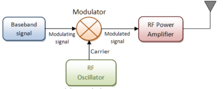
Fig.1: Modulation
Demodulation (downward frequency translation)
- It is the process of extracting the original information-carrying signal from a modulated carrier wave.
- A demodulator is an electronic circuit that is mainly used to recover the information from the modulated carrier wave.
- There are different types of demodulators.
- The output signal via demodulator may be sound, images or binary data.
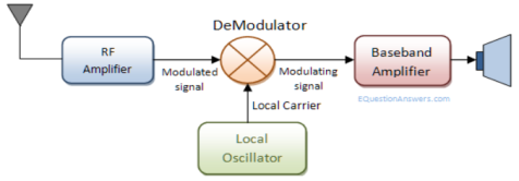
Fig.2: Demodulation
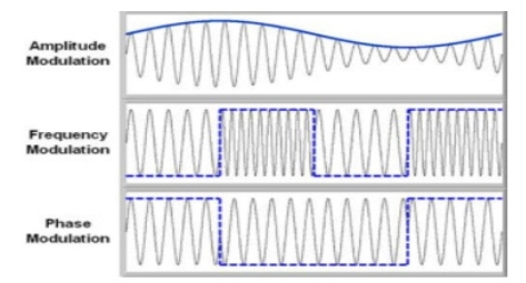
Fig.3: Demodulated Output
Necessity of Modulation: -
1>. Antenna height reduces
2>. Avoids mixing of signal
3>. Increases the range of communication [ In Kilometres]
4>. Multiplexing of signals is possible
5>. Improves quality of reception of signal.
1>. Antenna height Reduces: - Antenna theory specifies that the height of the antenna required for radiation of radio waves is a function of wavelength of the frequency fed at the i/p of the antenna. Antenna height must be multiple of ( d/4 ),
Where ‘d’ is the wavelength.
d = speed of light / frequency of signal
d = c / f = 3 x 10⁸ / f
Eg: Consider the voice as analog baseband signal with f = 4 KHz
d = 3 x 10⁸ / 4 x 10³
d = 75 x 103 m
d = 75 km
Height of antenna required is d / 4
= 75 km / 4 = 18.75 km
Q. Practically you cannot build the antenna of 18.7 km height. Consider this voice signal of 4 kHz frequency is used to modulate the carrier signal of 2 MHz frequency.
F = 2 MHz
D = c / f = 3 x 10⁸ / 2 x 106 = 150 m
Minimum height of antenna required = d / 4 = 150 / 4 = 37.5 m
Therefore, antenna height required for radio communication reduces from 75 km to 37.5 meters due to modulation.
2>. Increase range of communication: - The frequency of baseband signal is low. At low frequency the signal radiation from antenna is poor or weak. Due to this reason the signal gets attenuated and can’t travel long distance when it is transmitted.
Attenuation of the transmitted signal reduces when the frequency is increased.
Thus modulation increases the frequency of the signal to be radiated. Thus, increase in frequency increases the range of communication.
Key Takeaways:
- Modulation increases the frequency of the signal to be radiated.
- Antenna height must be multiple of ( d/4 ).
- Demodulation is the process of extracting the original information-carrying signal from a modulated carrier wave.
- Modulation is a process through which audio, video, image or text information is added to an electrical or optical carrier signal that is to be transmitted over a telecommunication or electronic medium.
The amplitude of the carrier signal varies in accordance with the instantaneous amplitude of the modulating signal. That is the amplitude of the carrier signal containing no information varies as per the amplitude of the signal containing information, at each instant.
Consider the following diagram
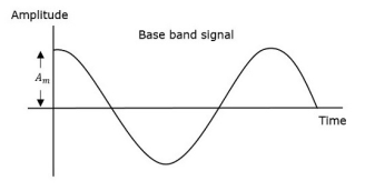
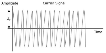
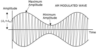
Fig.4: Amplitude Modulation
The first figure shows the modulating wave, which is the message signal. The next one is the carrier wave, which is a high frequency signal and contains no information. While, the last one is the resultant modulated wave.
It can be observed that the positive and negative peaks of the carrier wave are interconnected with an imaginary line. This line helps recreating the exact shape of the modulating signal. This imaginary line on the carrier wave is called as Envelope. It is the same as that of the message signal.
Therefore, we can say that Amplitude Modulation is the process of changing the amplitude of a relatively high frequency carrier signal in accordance with the amplitude of the modulating signal (Information). The carrier amplitude varies linearly by the modulating signal which usually consists of a range of audio frequencies. The frequency of the carrier is not affected.
The various forms of Amplitude Modulation are:
- Conventional Amplitude Modulation Full AM or Double Sideband Large carrier modulation (DSBLC) /Double Sideband Full Carrier (DSBFC)
- Double Sideband Suppressed carrier (DSBSC) modulation.
- Single Sideband (SSB) modulation
DSBSC (Double Side Band Suppressed Carrier)
In DSBC modulation, the modulated wave consists of only the upper and lower side bands. Transmitted power is saved through the suppression of the carrier wave, but the channel bandwidth requirement is the same.
DSBSC modulators make use of the multiplying action in which the modulating signal multiplies the carrier wave. In this system, the carrier component is eliminated and both upper and lower side bands are transmitted. As the carrier component is suppressed, the power required for transmission is less than that of AM.
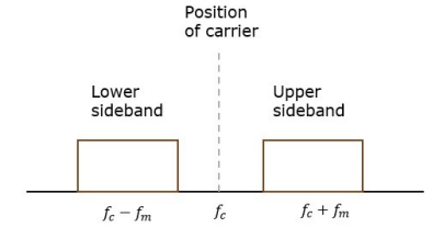
Fig. 5: Position of carrier
Carrier is suppressed and base band is allowed for transmission.
If m(t) = Am cos(2πfmt) is the modulating signal and c(t) = Ac cos(2πfct) is the carrier signal then DSBSC wave s(t) is given by
s(t) = c(t) m(t) ------------------- (1)
s(t) =Am cos(2πfmt) Ac cos(2πfct) -------- (2)
s(t) = Am Ac cos(2πfmt) cos(2πfct) ------- (3)
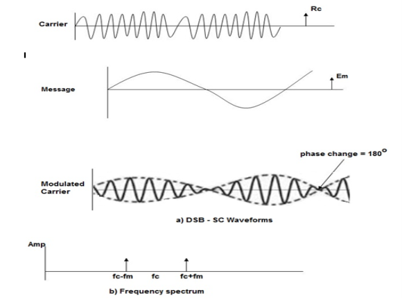
Fig. 6: DSBSC
The figure shows the waveform and the frequency spectrum.
The envelope of a DSBSC modulated signal is therefore different from the message signal and the Fourier transform of s(t) is given by
S(f) = Ac/2[ M(f-fc) + M(f + fc)]
When base band signal m(t) is limited to interval –W<fc<W we find the spectrum S(f) of the DSBSC wave s(t) as shown in the figure. We see that there is a change in the scaling factor, the modulation process translates the spectrum of the base band signal by fc. The transmission bandwidth is same as AM.
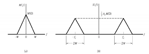
Fig. 7: DSBSC transmission bandwidth
Bandwidth of DSBSC Wave
We know the formula for bandwidth (BW) is
BW=fmax−fmin
Consider the equation of DSBSC modulated wave.
s(t)=AmAccos(2πfmt)cos(2πfct)s(t)
s(t)=AmAc2cos[2π(fc+fm)t]+AmAc2cos[2π(fc−fm)t]
The DSBSC modulated wave has only two frequencies. So, the maximum and minimum frequencies are fc+ fm and fc− fm respectively.
i.e.,fmax=fc+fm and fmin=fc−fm
BW=fc+fm−(fc−fm)
BW = 2fm
Thus, the bandwidth of DSBSC wave is same as that of AM wave and it is equal to twice the frequency of the modulating signal.
Power of DSBSC Wave
Consider the following equation of DSBSC modulated wave.
s(t)=AmAc2cos[2π(fc+fm)t]+AmAc2cos[2π(fc−fm)t]
Power of DSBSC wave is equal to the sum of powers of upper sideband and lower sideband frequency components.
Pt=PUSB+PLSB
We know the standard formula for power of cos signal is
P=vrms2 /R=(vm√2)2 /R
First, let us find the powers of upper sideband and lower sideband one by one.
Upper sideband power
PUSB=(AmAc/2√2)2/R=Am2Ac2 / 8R
Similarly, we will get the lower sideband power same as that of upper sideband power.
PLSB=Am2Ac2/8R
Now, let us add these two sideband powers in order to get the power of DSBSC wave.
Pt=Am2Ac2 /8R+Am2Ac2/8R
Pt=Am2Ac2 /4R
Therefore, the power required for transmitting DSBSC wave is equal to the power of both the sidebands.
The process of suppressing one of the sidebands along with the carrier and transmitting a single sideband is called as Single Sideband Suppressed Carrier system or simply SSBSC. It is plotted as shown in the following figure.
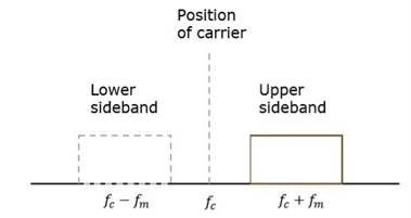
Fig.8 SSB
Carrier and sideband are suppressed and single sideband is allowed for transmission.
Let us consider the
Modulating signal
m(t)=Amcos(2πfmt)
Carrier signal
c(t)=Accos(2πfct)
Mathematically, we can represent the equation of SSB-SC wave as
s(t)=AmAc2cos[2π(fc+fm)t] for the upper sideband
Or
s(t)= AmAc2cos[2π(fc−fm)t] for the lower sideband
Bandwidth of SSB-SC Wave
We know that the DSB-SC modulated wave contains two sidebands and its bandwidth is 2fm. Since the SSB-SC modulated wave contains only one sideband, its bandwidth is half of the bandwidth of DSBSC modulated wave.
i.e., Bandwidth of SSBSC modulated wave =2fm/2=fm
Therefore, the bandwidth of SSB-SC modulated wave is fm and it is equal to the frequency of the modulating signal.
Power Calculations of SSB-SC Wave
Consider the following equation of SSBSC modulated wave.
s(t)=AmAc/2 cos[2π(fc+fm)t] for the upper sideband
Or
s(t)=AmAc/2 cos[2π(fc−fm)t] for the lower sideband
Power of SSB-SC wave is equal to the power of any one sideband frequency components.
Pt=PUSB=PLSB
We know power
P=vrms2 / R
=(vm/√2)2 / R
In this case, the power of the upper sideband is
PUSB=(AmAc/2√2)2 / R = Am2Ac2 /8R.
Similarly, for lower sideband power.
PLSB=Am2Ac2 / 8R
Therefore, the power of SSB-SC wave is
Pt=Am2Ac2 / 8R
Advantages
- Bandwidth or spectrum space occupied is lesser than AM and DSBSC waves.
- Transmission of more number of signals is allowed.
- Power is saved.
- High power signal can be transmitted.
- Less amount of noise is present.
- Signal fading is less likely to occur.
Disadvantages
- The generation and detection of SSBSC wave is a complex process.
- The quality of the signal gets affected unless the SSB transmitter and receiver have an excellent frequency stability.
Applications
- Power saving requirements and low bandwidth requirements.
- In land, air, and maritime mobile communications.
- Point-to-point communications.
- Radio communications.
- Television, telemetry, and radar communications.
- Military communications, such as amateur radio, etc.
We can get one sideband frequency component completely by using an ideal band pass filter. However, practically we may not get the entire sideband frequency component. Because of this, some information gets lost.
To avoid this loss, a technique is chosen, which is a compromise between DSBSC and SSBSC. This technique is known as Vestigial Side Band Suppressed Carrier (VSBSC) technique. The word “vestige” means “a part” from which, the name is derived.
VSBSC Modulation is the process, where a part of the signal called as vestige is modulated along with one sideband. The frequency spectrum of VSBSC wave is shown in the figure.
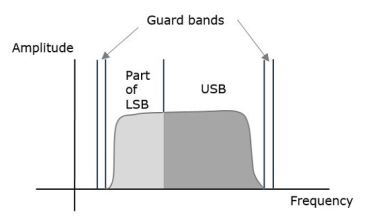
Along with the upper sideband, a part of the lower sideband is also transmitted in this technique. Similarly, we can transmit the lower sideband along with a part of the upper sideband. A guard band of very small width is laid on either side of VSB in order to avoid the interferences. VSB modulation is mostly used in television transmissions.
Bandwidth of VSBSC Modulation
We know that the bandwidth of SSBSC modulated wave is fm. Since the VSBSC modulated wave contains the frequency components of one side band along with the vestige of other sideband, the bandwidth of it will be the sum of the bandwidth of SSBSC modulated wave and vestige frequency fv.
Therefore,
Bandwidth of VSBSC Modulated Wave = fm+fv
Advantages
- Highly efficient.
- Reduction in bandwidth when compared to AM and DSBSC waves.
- Filter design is easy, since high accuracy is not needed.
- The transmission of low frequency components is possible, without any difficulty.
- Possesses good phase characteristics.
Disadvantages
- Bandwidth is more when compared to SSBSC wave.
- Demodulation is complex.
Applications
The most prominent and standard application of VSBSC is for the transmission of television signals. This is the most convenient and efficient technique when bandwidth usage is considered.
Generation of VSBSC
Generation of VSBSC wave is similar to the generation of SSBSC wave. The VSBSC modulator is shown in the following figure.
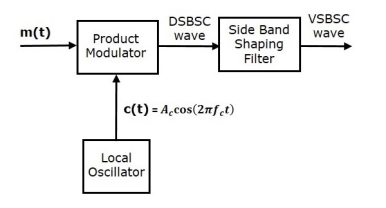
In this method, first we will generate DSBSC wave with the help of the product modulator. Then, apply this DSBSC wave as an input of sideband shaping filter. This filter produces an output, which is VSBSC wave.
The modulating signal m(t)) and carrier signal Ac cos(2πfct) are applied as inputs to the product modulator. Hence, the product modulator produces an output, which is the product of these two inputs.
Therefore, the output of the product modulator is
p(t)=Ac cos(2πfct)m(t)------------------------(1)
Apply Fourier transform on both sides
P(f)=Ac/2[M(f−fc)+M(f+fc)]-------------------(2)
The above equation represents the equation of DSBSC frequency spectrum.
Let the transfer function of the sideband shaping filter be H(f). This filter has the input p(t) and the output is VSBSC modulated wave s(t). The Fourier transforms of p(t) and s(t) are P(f) and S(f) respectively.
Mathematically, we can write
S(f)= =P(f)H(f)------------------(3)
Substitute P(f) value in the above equation.
S(f)=Ac/2[M(f−fc)+M(f+fc)]H(f)-----------------------------(4)
The above equation represents the equation of VSBSC frequency spectrum.
Demodulation of VSBSC
Demodulation of VSBSC wave is similar to the demodulation of SSBSC wave. Here, the same carrier signal used for generating VSBSC wave is used to detect the message signal. Hence, this process of detection is called as coherent or synchronous detection. The VSBSC demodulator is shown in the following figure.
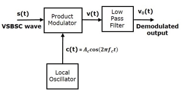
In this process, the message signal can be extracted from VSBSC wave by multiplying it with a carrier, which is having the same frequency and the phase of the carrier used in VSBSC modulation. The resulting signal is then passed through a Low Pass Filter. The output of this filter is the desired message signal.
Let the VSBSC wave be s(t) and the carrier signal is Ac cos(2πfct)
From the figure, we can write the output of the product modulator as
v(t)=Accos(2πfct)s(t)----------------------(1)
Apply Fourier transform on both sides
V(f)=Ac/2[S(f−fc)+S(f+fc)]--------------------------(2)
We know that
S(f)=Ac/2[M(f−fc)+M(f+fc)]H(f)-------------------------(3)
From the above equation, let us find S(f−fc)and S(f+fc).
S(f−fc)=Ac/2[M(f−fc−fc)+M(f−fc+fc)]H(f−fc)-----------------------------(4)
S(f−fc)=Ac/2[M(f−2fc)+M(f)]H(f−fc)------------------------------------(5)
S(f+fc)=Ac/2[M(f+fc−fc)+M(f+fc+fc)]H(f+fc)--------------- (6)
S(f+fc)=Ac/2[M(f)+M(f+2fc)]H(f+fc)---------------------------(7)
Substitute, S(f−fc) and S(f+fc) values in V(f)
V(f)=Ac/2[Ac/2[M(f−2fc)+M(f)]H(f−fc)+ Ac/2[M(f)+M(f+2fc)]H(f+fc)] ---------------------(8)
V(f)=Ac2 /4{M(f)[H(f−fc)+H(f+fc)]+Ac2 /4[M(f−2fc)H(f−fc)+M(f+2fc)H(f+fc)]--------------(9)

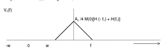
In the above equation, the first term represents the scaled version of the desired message signal frequency spectrum. It can be extracted by passing the above signal through a low pass filter.
V0(f)=Ac2 /4{M(f)[H(f−fc)+H(f+fc)]}-----------------------------------------(10)
Comparison
SL No | Parameter | SSB | DSB-SC | VSB |
1 | Power | Less | Medium | Less than DSB_SC |
2 | Bandwidth | Fm | 2fm | Fm<BW<2fm |
3 | Carrier Suppression | Yes | Yes | No |
4 | Receiver Complexity | Complex | Complex | Simple |
5 | Application | Point to point communication | Point to Point Communication | Television Broadcasting |
6 | Modulation Type | Linear | Linear | Linear |
7 | Sideband Suppression | One sided completely | No | One sideband suppressed partly |
8 | Transmission Efficiency | Maximum | Moderate | Moderate |
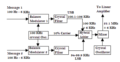
- ISB consists of two SSB channels added to form two side bands around the reduced carrier. Each sideband is quite independent of the other. It can simultaneously convey totally different transmission.
- Each channel of frequency 1ooHz to 6KHz is fed to its own balanced modulator , each modulator also receives the output of 100Khz crystal oscillator. Each modulator modulates each message (100Hz to 6KHz) on the frequency 100KHz.
- The USB filter and LSB filter suppresses the unwanted side band in such a way that one filter suppresses the Upper band and the other filter suppresses the Lower band.
- Both the outputs are added at the hybrid adder with 10% reduced carrier.
- The output is then fed to the balanced mixer where it mixes with the output of the crystal oscillator whose frequency is raised to 28.1 MHz – 6KHz.
Generation of double side band (DSB) with carrier
DSBFC (Double Side Band Full Wave Carrier)
Time-Domain Representation
Let the modulating signal be,
m(t)=Am cos (2πfmt) --------------(1)
And the carrier signal be,
c(t)=Ac cos(2πfct) c(t) ---------------(2)
Where, Am and Ac are the amplitude of the modulating signal and the carrier signal respectively.
fm and fc are the frequency of the modulating signal and the carrier signal respectively.
Then, the equation of Amplitude Modulated wave will be
s(t)= [Ac+ Am cos(2πfmt)] cos(2πfct) -------------------------- (3)
s(t) = [ Ac cos(2πfct) + Ac Am cos(2πfmt). Cos(2πfct] ---------(4)
s(t) = Ac [1 + Am/Ac cos(2πfmt)] cos(2πfct) ----------- (5)
Here the modulation index µ = Am/Ac.
s(t) = Ac [1 + µ cos(2πfmt)] cos(2πfct) -------------- (6)
Modulation index
Let Amax and Amin be the maximum and minimum amplitudes of the modulated wave.
We will get the maximum amplitude of the modulated wave, when cos(2πfmt)
Is 1.
That is Amax=Ac + Am
We will get the minimum amplitude of the modulated wave, when cos(2πfmt)
Is -1.
That is Amin = Ac - Am
Amax + Amin = Ac + Am + Ac –Am = 2Ac
Ac = Amax + Amin/2
Similarly,
Amax – Amin = Ac + Am – Ac +Am = 2Am
Am = Amax – Amin /2
Therefore

Bandwidth:
Bandwidth is the difference between the highest and lowest frequencies of the signal.
BW = fmax – fmin
s(t) = Ac [1+ μ cos(2πfmt)] cos(2πfct)
s(t) = Ac cos(2πfct) + Ac μ cos(2πfmt) cos(2πfct)
s(t) = Ac cos(2πfct) + Ac μ/2 cos 2π (fc + fm) t + Ac μ/2 cos 2π (fc - fm) t
Hence, the amplitude modulated wave has three frequencies.
- Carrier frequency fc
- Upper sideband frequency fc+fm
- And lower sideband frequency fc−fm
Here, fmax=fc+fm and fmin=fc−fm
BW=fc+fm−(fc−fm)
BW=fc+fm−(fc−fm)
BW= 2fm
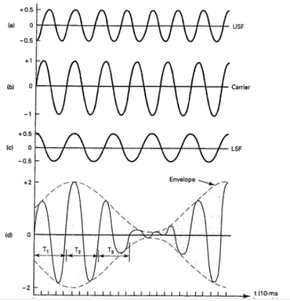
Fig. 9: DSBFC
Power Calculation of AM
Consider the following equation of amplitude modulated wave.
s(t)=Ac cos(2πfct)+Acμ 2 cos[2π(fc+fm)t]+ Acμ 2cos[2π(fc−fm)t] -------(1)
Power of AM wave is equal to the sum of powers of carrier, upper sideband, and lower sideband frequency components.
Pt=Pc+ PUSB+ PLSB
We know that the standard formula for power is
P = vrms 2 / R = (vm /  ) 2 /2
Where,
Vrms is the rms value of cos signal.
Vm is the peak value of cos signal.
The powers of the carrier, the upper and lower sideband is given by
Carrier power
Pc=(Ac/√2)2/R=Ac2/2R
Upper sideband power
PUSB=(Acμ/2√2)2/R= Ac2 μ2/ 8R
Similarly, for lower sideband power same as that of the upper side band power.
PLSB=(Acμ/2√2)2 /R
PLSB=Ac2μ2/R
Now, let us add these three powers in order to get the power of AM wave.
Pt=Ac2 /2R+Ac2μ2 /8R+Ac2μ2/8R
Pt= Ac2 /2R[ 1+μ2 /4+μ2 /4]
Pt=Pc ( 1+ μ 2/2 )
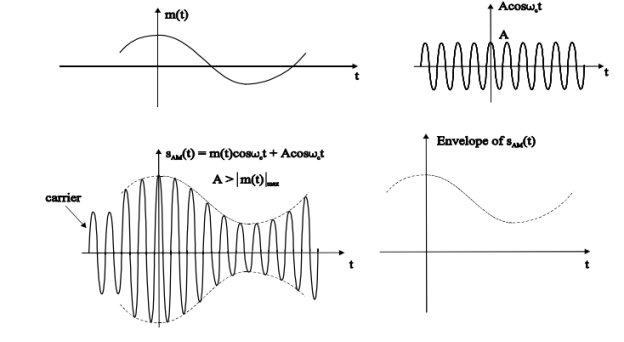
Fig. 10: DSBFC
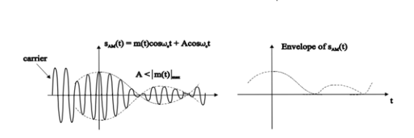
Fig. 11: DSBFC
Problems
A modulating signal m(t)=10cos(2π×103t)m(t) is amplitude modulated with a carrier signal c(t)=50cos(2π×105t). Find the modulation index, the carrier power, and the power required for transmitting AM wave.
Solution
Given, the equation of modulating signal as
m(t)=10 cos(2π×103t) m(t)
We know the standard equation of modulating signal as
m(t)=Am cos(2πfmt) m(t)
By comparing the above two equations, we will get
Am=10 volts
And Frequency of modulating signal as
Fm=103Hz=1KHz
Given, the equation of carrier signal is
c(t)=50 cos(2π×105t))
The standard equation of carrier signal is
c(t)=Ac cos(2πfct) c(t)
By comparing these two equations, we will get
Amplitude of carrier signal as Ac=50 volts
And Frequency of carrier signal as fc=105Hz=100KHz
We know the formula for modulation index as
μ=Am/Ac
μ=10/50=0.2
Therefore, the value of modulation index is 0.2 and percentage of modulation is 20%.
The formula for Carrier power, Pc
Pc=Ac2 /2R
Assume R=1ΩR=1Ω and substitute Ac value in the above formula.
Pc=(50)2/2(1)=1250W
Therefore, the Carrier power, Pc is 1250 watts.
We know the formula for power required for transmitting AM wave is
Pt=Pc(1+μ2/2)
Pt=1250(1+(0.2)22)=1275W
Therefore, the power required for transmitting AM wave is 1275 watts.
Key Takeaways:
- Power of AM wave is equal to the sum of powers of carrier, upper sideband, and lower sideband frequency components.
Pt=Pc+ PUSB+ PLSB
2. Bandwidth is the difference between the highest and lowest frequencies of the signal.
BW = fmax – fmin
3. Modulation index is given by µ = {Amax+ Amin/Amax-Amin}
It is so called because message signal is superimposed on +Vsb and then applied to the plate of a triode tube. The audio voltage is placed in series with the plate supply voltage af class C amplifier. In actual circuit Af signal is applied to the AF driver transformer which varies the grid bias of both triodes in accordance to the message signal. Due to which plate currents of both triodes vary with respect to the frequency of AF signal hence the voltage +Vbb applied to the plate of class C amplifier vary in accordance to the amplitude of the AF signal.
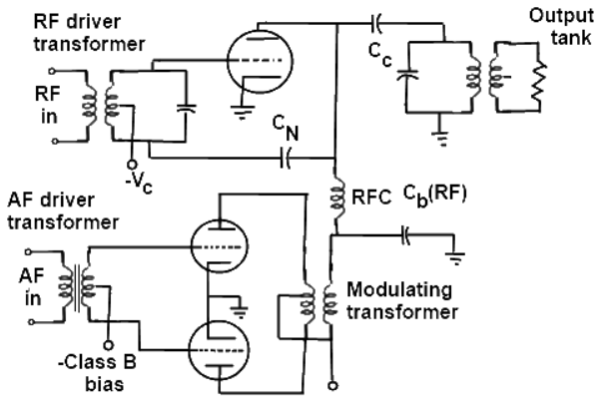
The voltage -Ve bias the grid of class C amplifier is controlled by the RF driver transformer. Due to which plate current varies in accordance to the RF. In this way the RF is superimposed on AF and the amplitude modulated signal is coupled to the load through the tuned transformer.
Another type of modulation in continuous-wave modulation is Angle Modulation.
Angle Modulation is the process in which the frequency or the phase of the carrier
Signal varies according to the message signal.
The standard equation of the angle modulated wave is
s(t)=Ac cos θi(t)-------------------(1)
Where:
Ac is the amplitude of the modulated wave, which is the same as the amplitude of the carrier signal
θi(t) is the angle of the modulated wave
Angle modulation is further divided into frequency modulation and phase modulation.
- Frequency Modulation is the process of varying the frequency of the carrier signal linearly with the message signal.
- Phase Modulation is the process of varying the phase of the carrier signal linearly with the message signal.
In frequency modulation, the frequency of the carrier varies whereas, in Phase Modulation (PM), the phase of the carrier signal varies in accordance with the instantaneous amplitude of the modulating signal.
So, in phase modulation, the amplitude and the frequency of the carrier signal remains constant.
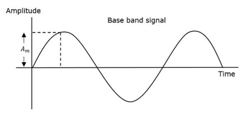
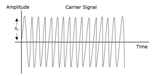
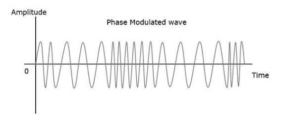
Fig 12 Angle Modulation
The phase of the modulated wave has infinite points, where the phase shift in a wave can take place. The instantaneous amplitude of the modulating signal changes the phase of the carrier signal. When the amplitude is positive, the phase changes in one direction and if the amplitude is negative, the phase changes in the opposite direction.
Representation
The equation for instantaneous phase ϕi in phase modulation is
ϕi=kpm(t)----------------------(1)
Where,
- Kp is the phase sensitivity
- m(t) is the message signal
The standard equation of angle modulated wave is
s(t)=Ac cos(2πfct+ϕi)---------------------------------(2)
Substitute, ϕi value in the above equation.
s(t)=Ac cos(2πfct+kpm(t))-----------------------------------(3)
This is the equation of PM wave.
If the modulating signal,
m(t)=Am cos(2πfmt)--------------------------------(4)
Then the equation of PM wave will be
s(t)=Ac cos(2πfct+βcos(2πfmt))-----------------------------------(5)
Where,
- β = modulation index = Δϕ=kpAm
- Δϕ is phase deviation
Phase modulation is used in mobile communication systems, while frequency modulation is used mainly for FM broadcasting.
Bessel Function and its Mathematical Analysis
Time – Domain Expression:
Since the FM wave is a nonlinear function of the modulating wave, the frequency modulation is a nonlinear process.
Let us consider a single-tone sinusoidal message signal defined by
n(t) = An cos(2nƒnt) -----------------------(1)
The instantaneous frequency is
ƒ(t) = ƒc+kƒAn cos(2nƒnt) -----------------------(2)
= ƒc+∆ƒ cos(2nƒnt)-----------------------------(3)
∆ƒ = kƒAn
 = 2 πfct + 2πKf
  m cos(2 πfmt) dt -------------------(4)
= 2 πfct + 2πKf Am / 2πfm sin(2πfmt) --------------------(5)
= 2 πfct + Kf Am/fm sin(2πfmt) ------------------------(6)
= 2 πfct + β f sin(2πfmt) ---------------------------(7)
Where β = ∆ƒ/fm = Kf Am/fm = modulation index.
Therefore, the single-tone FM wave is expressed by
FM(t) = Ac cos[2nƒct + þƒ sin(2nƒnt)] ------------------------------(8)
This isthe desired time-domain expression of the single-tone FM wave
Similarly, single-tone phase modulated wave may be determined where
PM(t) = Ac cos[2nƒct + kp An cos(2nƒnt)] -------------------------(9)
Or, PM(t) = Ac cos[2nƒct +þp cos(2nƒnt)] --------------------------(10)
þp = kpAn ---------------------------(11)
The frequency deviation of the single-tone PM wave is
FM(t) = Ac cos[2 πfct + β f sin(2πfmt)]-----------------(12)
Frequency Modulation
In amplitude modulation, the amplitude of the carrier signal varies, whereas in Frequency Modulation (FM), the frequency of the carrier signal varies in accordance with the instantaneous amplitude of the modulating signal.
Hence, in frequency modulation, the amplitude and the phase of the carrier signal remains constant.
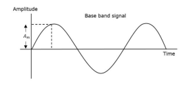
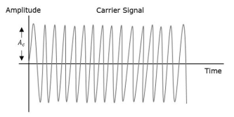
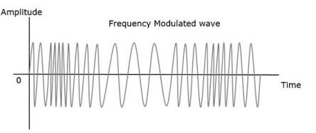
Fig 13 Frequency Modulation
- The frequency fi of the information signal controls the rate at which the carrier frequency increases and decreases. As with AM, fi must be less than fc. The amplitude of the carrier remains constant throughout this process.
- When the information voltage reaches its maximum value then the change in frequency of the carrier will have also reached its maximum deviation above the nominal value.
- Similarly, when the information reaches a minimum, the carrier will be at its lowest frequency below the nominal carrier frequency value.
- When the information signal is zero, then no deviation of the carrier will occur. The maximum change that can occur to the carrier from its base value fc is called the fc. This sets the dynamic range i.e. voltage frequency deviation, of the transmission. The dynamic range is the ratio of the largest and smallest analogue information signals that can be transmitted.
Representation:
The equation for instantaneous frequency fi in FM modulation is
fi=fc+ kf m(t)------------------------(1)
Where:
fc is the carrier frequency
kf is the frequency sensitivity
m(t) is the message signal
We know the relationship between angular frequency ωi and angle θi(t) as
ωi=dθi(t)/dt -------------------------(2)
2πfi=dθi(t)dt-------------------------(3)
θi(t)=2π  i dt -------------------------(4)
Substitute, fi value in the above equation.
θi(t)=2π  +kf m(t) dt-----------------(5)
θi(t)=2πfct+2πkf  (t)dt --------------------(6)
This is the equation of FM wave.
If the modulating signal is m(t)=Am cos(2πfmt) then the equation of FM wave will be
s(t)=Ac cos(2πfct+βsin(2πfmt)) -------------------(1)
Where:
β = modulation index =Δf/fm=kf Am/fm----------------------(2)
The difference between FM modulated frequency which is the instantaneous frequency and normal carrier frequency is termed as Frequency Deviation. It is denoted by Δf which is equal to the product of kf and Am.
FM can be divided into Narrowband FM and Wideband FM based on the values of modulation index β.
Problem:
A sinusoidal modulating waveform of amplitude 5 V and a frequency of 2 KHz is applied to FM generator, which has a frequency sensitivity of 40 Hz/volt. Calculate the frequency deviation, modulation index, and bandwidth.
Solution
Given,
The amplitude of modulating signal, Am=5V
Frequency of modulating signal, fm=2KHzf
Frequency sensitivity, kf=40Hz/volt
We know the formula for Frequency deviation as
Δf=kfAm --------------------(1)
Substitute kf and Am values in the above formula.
Δf=40×5=200Hz ----------------------(2)
Therefore, frequency deviation, Δf is 200Hz
The formula for modulation index is
β=Δf fm
Substitute Δf and fm values in the above formula.
β=200 x2×1000=0.1
Here, the value of modulation index, β is 0.1, which is less than one. Hence, it is Narrow Band FM.
The formula for Bandwidth of Narrow Band FM is the same as that of AM wave.
BW=2fm
Substitute fm value in the above formula.
BW=2×2K=4KHz
Therefore, the bandwidth of Narrow Band FM wave is 4KHz.
Problem 2
An FM wave is given by s(t)=20cos(8π×106t+9sin(2π×103t)) + 9 sin(2π×103t)). Calculate the frequency deviation, bandwidth and power of FM wave.
Solution
Given, the equation of an FM wave as
s(t)=20cos(8π×106t+9sin(2π×103t))-------------------------------(1)
We know the standard equation of an FM wave as
s(t)=Ac cos(2πfct+βsin(2πfmt))---------------------------------------(2)
We will get the following values by comparing the above two equations.
Amplitude of the carrier signal, Ac=20V
Frequency of the carrier signal, fc=4×10⁶Hz
Frequency of the message signal, fm=1×10³Hz=1KHz
Modulation index, β=9
Here, the value of modulation index is greater than one. Hence, it is Wide Band FM.
We know the formula for modulation index as
β=Δf .fm
Rearrange the above equation as follows.
Δf=β/fm
Substitute β and fm values in the above equation.
Δ=9×1K=9KHz
Therefore, frequency deviation, Δf is 9KHz.
The formula for Bandwidth of Wide Band FM wave is
BW=2(β+1)fm
Substitute β and fm values in the above formula.
BW=2(9+1)1K=20KHz
Therefore, the bandwidth of Wide Band FM wave is 20KHz
Formula for power of FM wave is
Pc=Ac2 /2R
Assume, R=1ΩR=1Ω and substitute AcAc value in the above equation.
P=(20)2 /2(1)=200W
Therefore, the power of FM wave is 200.
Frequency Spectrum and Eigen value
A spectrum represents the relative amounts of different frequency components in any signal. Its like the display on the graphic-equalizer in your stereo which has leds showing the relative amounts of bass, midrange and treble.
These correspond directly to increasing frequencies. In technical terms, the sines and cosines form a complete set of functions, also known as a basis in the infinite-dimensional vector space of real-valued functions (gag reflex).
Given that any signal can be thought to be made up of sinusoidal signals, the spectrum then represents the "recipe card" of how to make the signal from sinusoids.
Example: 1 part of 50 Hz and 2 parts of 200 Hz. Pure sinusoids have the simplest spectrum of all, just one component:

In this example, the carrier has 8 Hz and so the spectrum has a single component with value 1.0 at 8 Hz
The FM spectrum is considerably more complicated. The spectrum of a simple FM signal looks like:

The carrier is now 65 Hz, the modulating signal is a pure 5 Hz tone, and the modulation index is 2. What we see are multiple side-bands are the spikes other than the carrier frequency separated by the modulating frequency, 5 Hz.
There are roughly 3 side-bands on either side of the carrier. The shape of the spectrum may be explained using a simple heterodyne argument: when you mix the three frequencies (fc, fm and Df) together you get the sum and difference frequencies.
The largest combination is fc + fm + Df, and the smallest is fc - fm - Df. Since Df = b fm, the frequency varies (b + 1) fm above and below the carrier.
A more realistic example is to use an audio spectrum to provide the modulation:

In this example, the information signal varies between 1 and 11 Hz. The carrier is at 65 Hz and the modulation index is 2. The individual side-band spikes are replaced by a more-or-less continuous spectrum. However, the extent of the side-bands is limited approximately to (b + 1) fm above and below.
Here, that would be 33 Hz above and below, making the bandwidth about 66 Hz. We see the side-bands extend from 35 to 90 Hz, so out observed bandwidth is 65 Hz.
FM Performance
Bandwidth
As we have already shown, the bandwidth of a FM signal may be predicted using:
BW = 2 (b + 1 ) fm
Where b is the modulation index and
fm is the maximum modulating frequency used.
The bandwidth of an FM signal has a more complicated dependency than in the AM case .
In FM, both the modulation index and the modulating frequency affect the bandwidth. As the information is made stronger, the bandwidth also grows.
Efficiency
The efficiency of a signal is the power in the side-bands as a fraction of the total. In FM signals, because of the considerable side-bands produced, the efficiency is generally high.
The side-band structure is fairly complicated, but it is safe to say that the efficiency is generally improved by making the modulation index larger.
Noise
Noise generally is spread uniformly across the spectrum (the so-called white noise, meaning wide spectrum). The amplitude of the noise varies randomly at these frequencies.
FM systems are inherently immune to random noise. In order for the noise to interfere, it would have to modulate the frequency somehow.
But the noise is distributed uniformly in frequency and varies mostly in amplitude. As a result, there is virtually no interference picked up in the FM receiver.
FM is sometimes called "static free, " referring to its superior immunity to random noise.
Narrowband FM
Features of Narrowband FM
- This frequency modulation has a small bandwidth when compared to wideband FM.
- The modulation index ββ is small, i.e., less than 1.
- Its spectrum consists of the carrier, the upper sideband and the lower sideband.
- This is used in mobile communications such as police wireless, ambulances, taxicabs, etc.
Wideband FM
Features of Wideband FM
- This frequency modulation has infinite bandwidth.
- The modulation index ββ is large, i.e., higher than 1.
- Its spectrum consists of a carrier and infinite number of sidebands, which are located around it.
- This is used in entertainment, broadcasting applications such as FM radio, TV, etc.
Spectral Analysis of Single-Tone FM Wave
The above Eq. Can be written as
fM(t) = Re{Ac e j2nƒct e jþ sin(2nƒnt) }
For simplicity, the modulation index of FM is considered as þ instead of þƒ
Since sin(2nƒnt) is periodic with fundamental period T = 1⁄ƒn, the complex exponential e jþ sin(2nƒnt) is also periodic with the same fundamental period.
Therefore, this complex exponential can be expanded in Fourier series representation as where the Fourier series coefficients cn are obtained as
e j β sin(2πfmt) =  n ej2πnfmt ------------------------------------------(1)
Where the Fourier series coefficients cn are obtained as
Cn = 1/ T  j β sin(2πfmt) . e - j2πnfmt dt --------------------------------(2)
Let 2πfmt = x which reduces to
Cn = 1/ 2π  j β sin(x) e –jnx dx ----------------------------------(3)
= 1/ 2π  j( β sin(x) –nx) dx -------------------------------------(4)
This is known as nth order Bessel function of the first kind denoted by J n ( β) . Therefore
Cn= J n ( β) which can be written as
e j β sin(2πfmt) =  n ( β) e j2πfmt ---------------------------- (5)
Therefore
SFM(t) = Re { Ac  n ( β) e j2πfmt e j2nƒct }
= Ac  n ( β) cos[2π(fc+nfm)t] ---------------------------------(6)
If the modulating signal is m(t)=Am cos(2πfmt) then the equation of FM wave will be
s(t)=Ac cos(2πfct+βsin(2πfmt))-------------------(1)
Where,
β = modulation index =Δf/fm=kfAm/fm----------------------(2)
The difference between FM modulated frequency which is the instantaneous frequency and normal carrier frequency is termed as Frequency Deviation. It is denoted by Δf which is equal to the product of kf and Am.
FM can be divided into Narrowband FM and Wideband FM based on the values of modulation index β.
FM Performance
Bandwidth
As we have already shown, the bandwidth of a FM signal may be predicted using:
BW = 2 (b + 1 ) fm
Where b is the modulation index and
fm is the maximum modulating frequency used.
The bandwidth of an FM signal has a more complicated dependency than in the AM case .
In FM, both the modulation index and the modulating frequency affect the bandwidth. As the information is made stronger, the bandwidth also grows.
Key takeaway
Amplitude Modulation | Frequency Modulation |
Bandwidth is very small | It requires much wider channel as required to AM |
The amplitude of AM varies depending on the modulation index | The amplitude of FM signal is constant independent on the depth of modulation |
Area of reception is large | Area of reception is small |
The average power in modulated wave is greater than carrier power | The average power in frequency modulated wave is same as that of un-modulated wave. |
More susceptible to noise interference and low signal to noise ratio | Noise can be easily minimized amplitude variations can be eliminated by using limiter |
Maximum value of modulation index is 1 | No restriction on modulation index. |
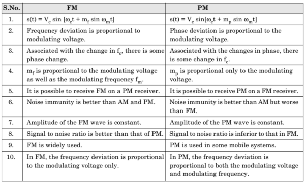
In frequency modulation, the frequency of the carrier varies whereas, in Phase Modulation (PM), the phase of the carrier signal varies in accordance with the instantaneous amplitude of the modulating signal.
So, in phase modulation, the amplitude and the frequency of the carrier signal remains constant.
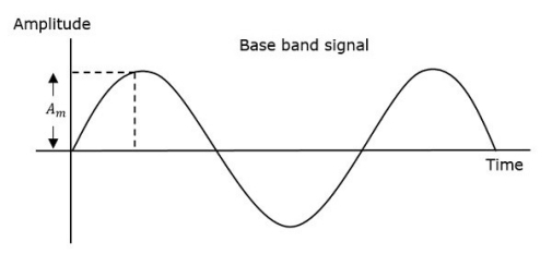
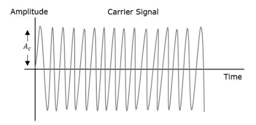
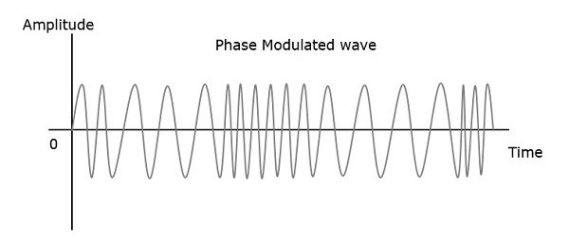
Fig 14. Angle Modulation
The phase of the modulated wave has infinite points, where the phase shift in a wave can take place. The instantaneous amplitude of the modulating signal changes the phase of the carrier signal. When the amplitude is positive, the phase changes in one direction and if the amplitude is negative, the phase changes in the opposite direction.
Representation
The equation for instantaneous phase ϕi in phase modulation is
ϕi=kpm(t)----------------------(1)
Where,
- Kp is the phase sensitivity
- m(t) is the message signal
The standard equation of angle modulated wave is
s(t)=Ac cos(2πfct+ϕi)---------------------------------(2)
Substitute, ϕi value in the above equation.
s(t)=Ac cos(2πfct+kpm(t))-----------------------------------(3)
This is the equation of PM wave.
If the modulating signal,
m(t)=Am cos(2πfmt)--------------------------------(4)
Then the equation of PM wave will be
s(t)=Ac cos(2πfct+βcos(2πfmt))-----------------------------------(5)
Where,
- β = modulation index = Δϕ=kpAm
- Δϕ is phase deviation
Phase modulation is used in mobile communication systems, while frequency modulation is used mainly for FM broadcasting.
Generation of FM
FM waves are normally generated by two methods:
- Indirect method
- Direct method.
Indirect Method (Armstrong Method) of FM Generation
In this method, narrow-band FM wave is generated first by using phase modulator and then the wideband FM with desired frequency deviation is obtained by using frequency multipliers.
s(t) = Ac cos[2π fct + 2 π Kf  ] --------------------(1)
s(t) = Ac cos(2π fct) cos[(t)] – Ac sin(2π fct) sin [[(t)]-----------------(2)
The above equation is the expression for narrow band FM wave . In this case
Cos [(t)]  1 and sin[[(t)]
  1
1
s(t) = Ac cos(2π fct) – Ac sin(2π fct) [(t)] -----------------------(3)
s(t) = Ac cos(2π fct) – 2 Ac kf sin(2π fct)  --------------------(4)
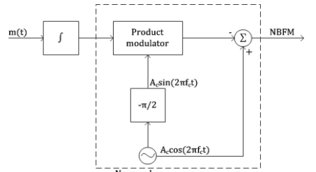
Fig 15. Narrow band phase modulator
Narrow Band FM Generator
- The frequency deviation ∆ƒ is very small in narrow-band FM wave. To produce wideband FM, we have to increase the value of ∆ƒ to a desired level.
- This is achieved by means of one or multiple frequency multipliers.
- A frequency multiplier consists of a nonlinear device and a bandpass filter. The nth order nonlinear device produces a dc component and n number of frequency modulated waves with carrier frequencies ƒc, 2ƒc, … nƒc and frequency deviations ∆ƒ, 2∆ƒ, … n∆ƒ, respectively.
- If we want an FM wave with frequency deviation of 6∆ƒ, then we may use a 6th order nonlinear device or one 2nd order and one 3rd order nonlinear devices in cascade followed by a bandpass filter centered at 6ƒc.
- Usually we may require very high value of frequency deviation. This automatically increases the carrier frequency by the same factor which may be higher than the required carrier frequency.
- We may shift the carrier frequency to the desired level by using mixer which does not change the frequency deviation.
- The narrowband FM has some distortion due to the approximation made in deriving the expression of narrowband FM from the general expression.
- This produces some amplitude modulation in the narrowband FM which is removed by using a limiter in frequency multiplier.
Direct Method of FM Generation
- In this method, the instantaneous frequency ƒ(t) of the carrier signal c(t) is varied directly with the instantaneous value of the modulating signal n(t).
- For this, an oscillator is used in which any one of the reactive components (either C or L) of the resonant network of the oscillator is varied linearly with n(t).
- We can use a varactor diode or a varicap as a voltage variable capacitor whose capacitance solely depends on the reverse-bias voltage applied across it.
- To vary such capacitance linearly with n(t), we have to reverse-bias the diode by the fixed DC voltage and operate within a small linear portion of the capacitance-voltage characteristic curve.
- The unmodulated fixed capacitance C0 is linearly varied by n(t) such that the resultant capacitance becomes C(t) = C0 − kn(t) where the constant k is the sensitivity of the varactor diode.
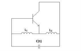
Fig 16. Hartley Oscillator
The figure shows the simplified diagram of the Hartley oscillator which is implemented as discussed above. The frequency of oscillation for such an oscillator is given by
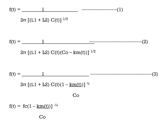
Where fc is the un modulated frequency of oscillation. Assuming,
k m(t)/C0 << 1
We have binomial expansion as
(1 – km(t)/Co) -1/2  1 + k m(t)/ 2C0 ------------------------------------------------(4)
f(t)  fc( 1 + km(t)/2Co)
= fc + k fc m(t) / 2Co ----------------------------------------------------(5)
f(t) fc + kf m(t) ----------------------------------------(6)
Kf = kfc/ 2Co -------------------------------------- (7)
Equation(7) is the frequency sensitivity of the modulator.
This equation is the required expression for the instantaneous frequency of an FM wave.
In this way, we can generate an FM wave by direct method. The main advantage of the direct method is that it produces sufficiently high frequency deviation, thus requiring little frequency multiplication.
But, it has poor frequency stability. A feedback scheme is used to stabilize the frequency in which the output frequency as compared with the constant frequency generated by highly stable crystal oscillator and the error signal is feedback to stabilize the frequency.
Pre-Emphasis:
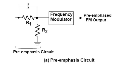
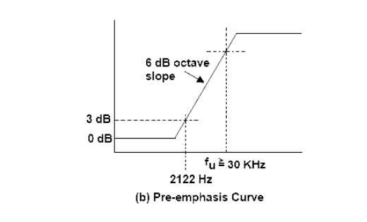
At the transmitter, the modulating signal is passed through a simple network which amplifies the high frequency, components more than the low-frequency components. The simplest form of such a circuit is a simple high pass filter of the type shown in fig (a). Specification dictate a time constant of 75 microseconds (µs) where t = RC. Any combination of resistor and capacitor (or resistor and inductor) giving this time constant will be satisfactory. Such a circuit has a cutoff frequency fco of 2122 Hz. This means that frequencies higher than 2122 Hz will he linearly enhanced. The output amplitude increases with frequency at a rate of 6 dB per octave. The pre-emphasis curve is shown in Fig (b). This pre-emphasis circuit increases the energy content of the higher-frequency signals so that they will tend to become stronger than the high frequency noise components. This improves the signal to noise ratio and increases intelligibility and fidelity.
De-Emphasis Circuit:
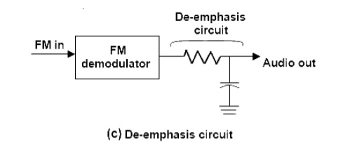
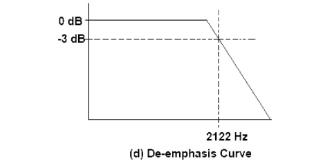
De-emphasis means attenuating those frequencies by the amount by which they are boosted. However, pre-emphasis is done at the transmitter and the de-emphasis is done in the receiver. The purpose is to improve the signal-to-noise ratio for FM reception. A time constant of 75µs is specified in the RC or L/Z network for pre-emphasis and de-emphasis.
References:
1. Communication Systems - B.P Lathi, BS Publication
2. Lathi B.P. - Modern Digital and Analog communications systems - PRISM Indian Ed.
3. Simon Haykin, “Digital Communication Systems”,JohnWiley&Sons,