Unit - 5
Review of channel coding and spread spectrum
In channel encoder a block of k-msg bits is encoded into a block of n bits by adding (n-k) number of check bits as shown in figure.

Fig 1. Linear Block Code
A (n,k) block code is said to be a (n,k) linear block code if it satisfies the condition
Let C1 and C2 be any two code words belonging to a set of (n,k) block code
Then C1 C2 is also an n-bit code word belonging to the same set of (n,k ) block code.
A (n,k) linear block code is said to be systematic if k-msg bits appear either at the beginning or end of the code word.
Matrix Description of linear block codes:
Let the message block of k-bits be represented as row vector called as message vector given by
[D ] = { d1,d2………………dk}
Where d1,d2………………dk are either 0’s 0r 1’s
The channel encoder systematically adds(n-k) number of check bits toform a (n,k) linear block code. Then the 2k code vector can be represented by
C = {c1,c2……………cn) ----------------------------(2)
In a systematic linear block code the msg bits appear at the beginning of the code vector
Therefore ci=di for all I = 1 to k.---------------------------------(3)
The remaining n-k bits are check bits . Hence eq(2) and (3) can be combined into
[C] = { C1,C2,C3……………………..Ck, Ck+1,Ck+2 ……………………Cn}
These (n-k) number of check bits ck+1,Ck+2 ………………. Cn are derived from k-msg bits using predetermined rule below:
Ck+1 =P11d1 + P21 d2 +………………….+ Pk1dk
Ck+2 = P21 d1 + P22 d2 +………………….+ Pk2dk
……………………………………………………….
Ck+n = P1,n-kd1+ P2,n-k d2 + ……………………+ Pk,n-kdk
Where P11,P21 …………. Are either 0’s or 1’s addition is performed using modulo 2 arithmetic
In matrix form
[c1 c2………….cn] = [d1,d2…………………dn] [ 1 0 0 0 P11 P12 ……….P1n-k]
--------------------------
0 0 0 Pk1…………………… Pk,n-k
0r [C] = [D] [G]
[G] = [Ik |P](kxn)
Where Ik is the unit matrix of order ‘k’
[P] = parity matrix of order kx (n-k)
I = denotes demarkation between Ik and P
The generator matrix can be expressed as
[G] = [P | Ik]
Associted with the generator matrix [G] another matrix order (n-k) x n matrix is called the parity check matrix.
Given by
[H ] = [ PT | I n-k]
Where PT represents parity transpose matrix.
Examples
Q1) The generator matrix for a block code is given below. Find all code vectors of this code

A1) The Generator matrix G is generally represented as


On comparing,
The number of message bits, k = 3
The number of code word bits, n = 6
The number of check bits, q = n – k = 6 – 3 = 3
Hence, the code is a (6, 3) systematic linear block code. From the generator matrix, we have Identity matrix

The coefficient or submatrix,

Therefore, the check bits vector is given by,

On substituting the matrix form,

From the matrix multiplication, we have


On simplifying, we obtain


Hence the check bits (c1 c2 c3) for each block of (m1 m2 m3) message bits can be determined.
(i) For the message block of (m1 m2 m3) = (0 0 0), we have


(ii) For the message block of (m1 m2 m3) = (0 0 1), we have


(iii) For the message block of (m1 m2 m3) = (0 1 0), we have


Similarly, we can obtain check bits for other message blocks.
Binary cyclic codes are a subclass of the linear block codes. They have very good features which make them extremely useful. Cyclic codes can correct errors caused by bursts of noise that affect several successive bits. The very good block codes like the Hamming codes, BCH codes and Golay codes are also cyclic codes. A linear block code is called as cyclic code if every cyclic shift of the code vector produces another code vector. A cyclic code exhibits the following two properties.
(i) Linearity Property: A code is said to be linear if modulo-2 addition of any two code words will produce another valid codeword.
(ii) Cyclic Property: A code is said to be cyclic if every cyclic shift of a code word produces another valid code word. For example, consider the n-bit code word, X = (xn-1, xn-2, ….. x1, x0).
If we shift the above code word cyclically to left side by one bit, then the resultant code word is
X’ = (xn-2, xn-3, ….. x1, x0, xn-1)
Here X’ is also a valid code word. One more cyclic left shift produces another valid code vector X’’.
X’’ = (xn-3, xn-4, ….. x1, x0, xn-1, xn-2)
Representation of codewords by a polynomial
• The cyclic property suggests that we may treat the elements of a code word of length n as the coefficients of a polynomial of degree (n-1).
• Consider the n-bit code word, X = (xn-1, xn-2, ….. x1, x0)
This code word can be represented in the form of a code word polynomial as below:
X (p) = xn-1p n-1 + xn-2pn-2 + ….. + x1p + x0
Where X (p) is the polynomial of degree (n-1). p is an arbitrary real variable. For binary codes, the coefficients are 1s or 0s.
- The power of ‘p’ represents the positions of the code word bits. i.e., pn-1 represents MSB and p0 represents LSB.
- Each power of p in the polynomial X(p) represents a one-bit cyclic shift in time. Hence, multiplication of the polynomial X(p) by p may be viewed as a cyclic shift or rotation to the right, subject to the constraint that pn = 1.
- We represent cyclic codes by polynomial representation because of the following reasons.
1. These are algebraic codes. Hence algebraic operations such as addition, subtraction, multiplication, division, etc. becomes very simple.
2. Positions of the bits are represented with the help of powers of p in a polynomial.
A) Generation of code vectors in non-systematic form of cyclic codes
Let M = (mk-1, mk-2, …… m1, m0) be ‘k’ bits of message vector. Then it can be represented by the polynomial as,
M(p) = mk-1pk-1 + mk-2pk-2 + ……+ m1p + m0
The codeword polynomial X(P) is given as X (P) = M(P) . G(P)
Where G(P) is called as the generating polynomial of degree ‘q’ (parity or check bits q = n – k). The generating polynomial is given as G (P) = pq + gq-1pq-1+ …….. + g1p + 1
Here gq-1, gq-2 ….. g1 are the parity bits.
• If M1, M2, M3, …… etc. are the other message vectors, then the corresponding code vectors can be calculated as,
X1 (P) = M1 (P) G (P)
X2 (P) = M2 (P) G (P)
X3 (P) = M3 (P) G (P) and so on
All the above code vectors X1, X2, X3 ….. Are in non-systematic form and they satisfy cyclic property.
The generator polynomial of a (7, 4) cyclic code is G(p) = p3 + p + 1. Find all the code vectors for the code in non-systematic form
Here n = 7, k = 4
Therefore, q = n – k = 7 – 4 = 3
Since k = 4, there will be a total of 2k = 24 = 16 message vectors (From 0 0 0 0 to 1 1 1 1). Each can be coded in to a 7 bits codeword.
(i) Consider any message vector as
M = (m3 m2 m1 m0) = (1 0 0 1)
The general message polynomial is M(p) = m3p3 + m2p2 + m1p + m0, for k = 4
For the message vector (1 0 0 1), the polynomial is
M(p) = 1. p3 + 0. p2 + 0. p + 1
M(p) = P3 + 1
The given generator polynomial is G(p) = p3 + p + 1
In non-systematic form, the codeword polynomial is X (p) = M (p). G (p)
On substituting,
X (p) = (p3 + 1). (p3 + p +1)
= p6 + p4 + p3 + p3 + p +1
= p6 + p4 + (1 1) p3 + p +1
= p6 + p4 + p + 1
= 1.p6 + 0.p5 + 1.p4 + 0.p3 + 0.p2 + 1.p + 1
The code vector corresponding to this polynomial is
X = (x6 x5 x4 x3 x2 x1 x0)
X = (1 0 1 0 0 1 1)
(ii) Consider another message vector as
M = (m3 m2 m1 m0) = (0 1 1 0)
The polynomial is M(p) = 0.p3 + 1.p2 + 1.p1 + 0.1
M(p) = p2 + p
The codeword polynomial is
X(p) = M(p). G(p)
X(p) = (p2 + p). (p3 + p + 1)
= p5 + p3 + p2 + p4 + p2 + p
= p5 + p4 + p3 + (1 1) p2 + p
= p5 + p4 + p3 + p
= 0.p6 + 1.p5 + 1.p4 + 1.p3 + 0.p2 + 1.p + 0.1
The code vector, X = (0 1 1 1 0 1 0)
Similarly, we can find code vector for other message vectors also, using the same procedure.
B) Generation of code vectors in systematic form of cyclic codes
The code word for the systematic form of cyclic codes is given by
X = (k message bits ⋮q check bits)
X = (mk-1 mk-2 …….. m1 m0⋮ cq-1 cq-2 ….. c1 c0)
In polynomial form, the check bits vector can be written as
C(p) = cq-1pq-1 + cq-2pq-2 + …….. + c1p + c0
In systematic form, the check bits vector polynomial is obtained by
C(p) = rem [𝑝𝑞. 𝑀 (𝑝)/𝐺(𝑝) ]
Where:
M(p) is message polynomial
G(p) is generating polynomial
‘rem’ is remainder of the division
The generator polynomial of a (7, 4) cyclic code is G(p) = p3 + p + 1. Find all the code vectors for the code in systematic form.
Here n = 7, k = 4
Therefore, q = n - k = 7 – 4 = 3
Since k = 4, there will be a total of 2k = 24 = 16 message vectors (From 0 0 0 0 to 1 1 1 1). Each can be coded into a 7 bits codeword.
(i) Consider any message vector as
M = (m3 m2 m1 m0) = (1 1 1 0)
By message polynomial,
M(p) = m3p3 + m2p2 + m1p + m0, for k = 4.
For the message vector (1 1 1 0), the polynomial is
M(p) = 1.p3 + 1.p2 + 1.p + 0.1
M(p) = p3 + p2 + p
The given generator polynomial is G(p) = p3 + p + 1
The check bits vector polynomial is


We perform division as per the following method.
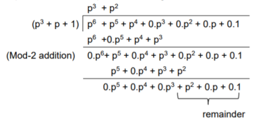
Thus, the remainder polynomial is p2 + 0.p + 0.1.
This is the check bits polynomial C(p)
c(p) = p2 + 0.p + 0.1
The check bits are c = (1 0 0)
Hence the code vector for the message vector (1 1 1 0) in systematic form is
X = (m3 m2 m1 m0⋮ c2 c1 c0) = (1 1 1 0 1 0 0)
(ii) Consider another message vector as
M = (m3 m2 m1 m0) = (1 0 1 0)
The message polynomial is M(p) = p3 + p
Then the check bits vector polynomial is


The division is performed as below.
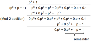
Thus, the check bits polynomial is C(p) = 0.p2 + 1.p + 1.1
The check bits are C = (0 1 1)
Hence the code vector is X= (1 0 1 0 0 1 1)
Similarly, we can find code vector for other message vectors also, using the same procedure.
Cyclic Redundancy Check Code (CRC)
Cyclic codes are extremely well-suited for error detection. Because they can be designed to detect many combinations of likely errors. Also, the implementation of both encoding and error detecting circuits is practical. For these reasons, all the error detecting codes used in practice are of cyclic code type. Cyclic Redundancy Check (CRC) code is the most important cyclic code used for error detection in data networks & storage systems. CRC code is basically a systematic form of cyclic code.
CRC Generation (encoder)
The CRC generation procedure is shown in the figure below.
- Firstly, we append a string of ‘q’ number of 0s to the data sequence. For example, to generate CRC-6 code, we append 6 number of 0s to the data.
- We select a generator polynomial of (q+1) bits long to act as a divisor. The generator polynomials of three CRC codes have become international standards. They are
- CRC – 12 code: p12 + p11 + p3 + p2 + p + 1
- CRC – 16 code: p16 + p15 + p2 + 1
- CRC – CCITT Code: p16 + p12 + p5 + 1
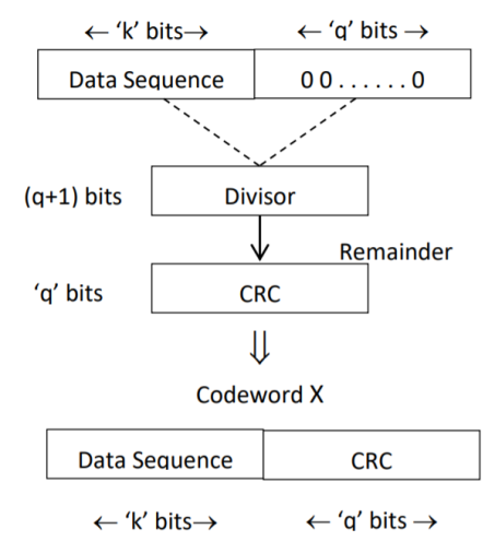
Fig 2. CRC Generation
- We divide the data sequence appended with 0s by the divisor. This is a binary division.
- The remainder obtained after the division is the ‘q’ bit CRC. Then, this ‘q’ bit CRC is appended to the data sequence. Actually, CRC is a sequence of redundant bits.
- The code word generated is now transmitted.
CRC checker
The CRC checking procedure is shown in the figure below. The same generator polynomial (divisor) used at the transmitter is also used at the receiver.
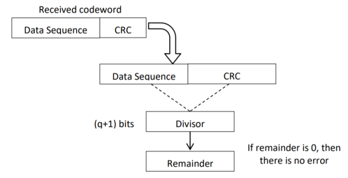
Fig 3. CRC checker
- We divide the received code word by the divisor. This is also a binary division.
- If the remainder is all 0s, then there are no errors in the received codeword, and hence must be accepted.
- If we have a non-zero remainder, then we infer that error has occurred in the received code word. Then this received code word is rejected by the receiver and an ARQ signalling is done to the transmitter.
Generate the CRC code for the data word of 1 1 1 0. The divisor polynomial is p3 + p + 1
Data Word (Message bits) = 1 1 1 0
Generator Polynomial (divisor) = p3 + p + 1
Divisor in binary form = 1 0 1 1
The divisor will be of (q + 1) bits long. Here the divisor is of 4 bits long. Hence q = 3. We append three 0s to the data word.
Now the data sequence is 1 1 1 0 0 0 0. We divide this data by the divisor of 1 0 1 1. Binary division is followed.
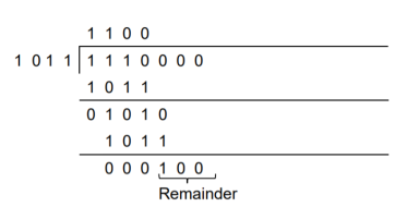
The remainder obtained from division is 100. Then the transmitted codeword is 1 1 1 0 1 0 0.
A codeword is received as 1 1 1 0 1 0 0. The generator (divisor) polynomial is p3 + p + 1. Check whether there is error in the received codeword.
Received Codeword = 1 1 1 0 1 0 0
Divisor in binary form = 1 0 1 1
We divide the received codeword by the divisor.
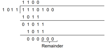
The remainder obtained from division is zero. Hence there is no error in the received codeword.
Key takeaway
- Cyclic codes can correct burst errors that span many successive bits.
- They have an excellent mathematical structure. This makes the design of error correcting codes with multiple-error correction capability relatively easier.
- The encoding and decoding circuits for cyclic codes can be easily implemented using shift registers.
- The error correcting and decoding methods of cyclic codes are simpler and easy to implement. These methods eliminate the storage (large memories) needed for lookup table decoding. Therefore, the codes become powerful and efficient.
In block coding, the encoder accepts a k-bit message block and generates an n-bit code word. Thus, code words are produced on a block-by-block basis. Therefore, a buffer is required in the encoder to place the message block. A subclass of Tree codes is convolutional codes. The convolutional encoder accepts the message bits continuously and generates the encoded codeword sequence continuously. Hence there is no need for buffer. But in convolutional codes, memory is required to implement the encoder.
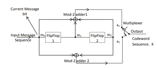
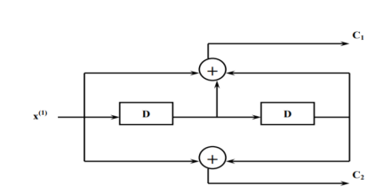
Fig 4. Convolutional Encoder
In a convolutional code, the encoding operation is the discrete-time convolution of the input data sequence with the impulse response of the encoder. The input message bits are stored in the fixed length shift register and they are combined with the help of mod-2 adders. This operation is equivalent to binary convolution and hence it is called convolutional coding. The figure above shows the connection diagram for an example convolutional encoder.
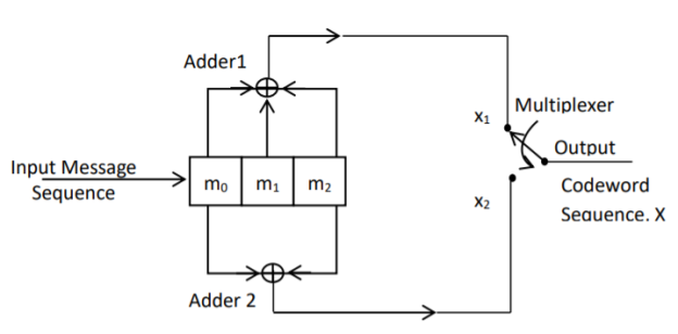
Fig 5. Convolutional Encoder redrawn alternatively
The encoder of a binary convolution code may be viewed as a finite-state machine. It consists of M-stage shift register with prescribed connections to modulo2 adders. A multiplexer serializes the outputs of the adders. The convolutional codes generated by these encoders of Figure above are non-systematic form. Consider that the current message bit is shifted to position m0. Then m1 and m2 store the previous two message bits. Now, by mod-2 adders 1 and 2 we get the new values of X1 and X2. We can write
X1 = m0 m1 m2 and
X2 = m0 m2
The multiplexer switch first samples X1 and then X2. Then next input bit is taken and stored in m0. The shift register then shifts the bit already in m0 to m1. The bit already in m1 is shifted to m2. The bit already in m2 is discarded. Again, X1 and X2 are generated according to this new combination of m0, m1 and m2. This process is repeated for each input message bit. Thus, the output bit stream for successive input bits will be,
X = x1 x2 x1 x2 x1 x2…….. And so on
In this convolutional encoder, for every input message bit, two encoded output bits X1 and X2 are transmitted. Hence number of message bits, k = 1. The number of encoded output bits for one message bit, n = 2.
Code rate: The code rate of this convolutional encoder is given by
Code rate, r = 𝑀𝑒𝑠𝑠𝑎𝑔𝑒 𝑏𝑖𝑡𝑠 (𝑘)/𝑒𝑛𝑐𝑜𝑑𝑒𝑟 𝑜𝑢𝑡𝑝𝑢𝑡 𝑏𝑖𝑡𝑠 (𝑛) = 𝑘/𝑛 = 1/2 where 0 < r < 1
Constraint Length: The constraint length (K) of a convolution code is defined as the number of shifts over which a single message bit can influence the encoder output. It is expressed in terms of message bits. For the encoder of Figure above, constraint length is K = 3 bits. Because, a single message bit influences encoder output for three successive shifts. At the fourth shift, the message bit is lost and it has no effect on the output. For the encoder of Figure above, whenever a particular message bit enters the shift register, it remains in the shift register for three shifts ie.,
First Shift → Message bit is entered in position m0.
Second Shift → Message bit is shifted in position m1.
Third Shift → Message bit is shifted in position m2.
Constraint length ‘K’ is also equal to one plus the number of shift registers required to implement the encoder.
Dimension of the Code
The code dimension of a convolutional code depends on the number of message bits ‘k’, the number of encoder output bits, ‘n’ and its constraint length ‘K’. The code dimension is therefore represented by (n, k, K). For the encoder shown in figure above, the code dimension is given by (2, 1, 3) where n = 2, k = 1 and constraint length K = 3.
Graphical representation of convolutional codes
Convolutional code structure is generally presented in graphical form by the following three equivalent ways.
1. By means of the state diagram
2. By drawing the code trellis
3. By drawing the code tree
These methods can be better explained by using an example.
For the convolutional encoder given below in Figure 3.11, determine the following. a) Code rate b) Constraint length c) Dimension of the code d) Represent the encoder in graphical form.
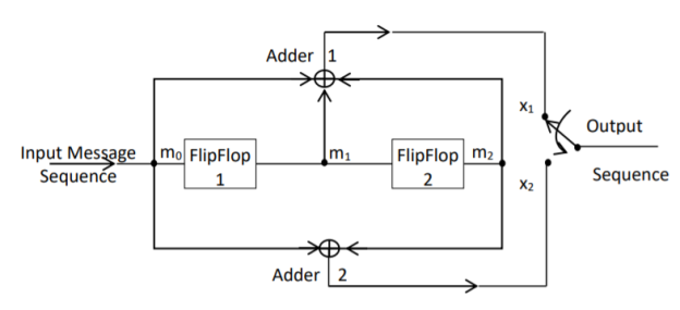
a) Code rate:
The code rate, r = 𝑘/𝑛. The number of message bits, k = 1.
The number of encoder output bits, n = 2.
Hence code rate, r = 1/2
b) Constraint length:
Constraint length, k = 1 + number of shift registers.
Hence k = 1 + 2 = 3
c) Code dimension:
Code dimension = (n, k,K) = (2, 1, 3)
Hence the given encoder is of ½ rate convolutional encoder of dimension (2, 1, 3).
d) Graphical form representation
The encoder output is X = (x1 x2 x1 x2 x1 x2 ….. And so on)
The Mod-2 adder 1 output is x1 = m0 m1 m2
The Mod-2 adder 2 output is x2 = m0 m2.
We can represent the encoder output for possible input message bits in the form of a Logic table.
| Input message bit | Present state | Next state | Encoder outpt | |||
 |  |  |  |  |  |  | |
A | 0 | 0 | 0 | 0 | 0 | 0 | 0 |
1 | 0 | 0 | 1 | 0 | 1 | 1 | |
B | 0 | 1 | 0 | 0 | 1 | 1 | 0 |
1 | 1 | 0 | 1 | 1 | 0 | 1 | |
C | 0 | 0 | 1 | 0 | 0 | 1 | 1 |
1 | 0 | 1 | 1 | 0 | 0 | 0 | |
D | 0 | 1 | 1 | 0 | 1 | 0 | 1 |
1 | 1 | 1 | 1 | 1 | 1 | 0 | |
Output x1 = m0 m1 m2 and x2 = m0 m2
- The encoder output depends on the current input message bit and the contents in the shift register ie., the previous two bits.
- The present condition of the previous two bits in the shift register may be in four combinations. Let these combinations 00, 10, 01 and 11 be corresponds to the states A, B, C and D respectively.
- For each input message bit, the present state of the m1 and m2 bits will decide the encoded output.
- The logic table presents the encoded output x1 and x2 for the possible ‘0’ or ‘1’ bit input if the present state is A or B or C or D.
1. State diagram representation
- The state of a convolutional encoder is defined by the contents of the shift register. The number of states is given by 2k-1 = 23-1 = 22 = 4. Here K represents the constraint length.
- Let the four states be A = 00, B = 10, C = 01 and D = 11 as per the logic table. A state diagram as shown in the figure below illustrates the functioning of the encoder.
- Suppose that the contents of the shift register is in the state A = 00. At this state, if the incoming message bit is 0, the encoder output is X = (x1 x2) = 00. Then if the m0, m1 and m2 bits are shifted, the contents of the shift register will also be in state A = 00. This is represented by a solid line path starting from A and ending at A itself.
- At the ‘A’ state, if the incoming message bit is 1, then the encoder output is X = 11. Now if the m0, m1 and m2 bits are shifted, the contents of the shift register will become the state B = 10. This is represented by a dashed line path starting from A and ending at B.
- Similarly, we can draw line paths for all other states, as shown in the Figure below.
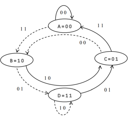
Fig 6. State Diagram
2. Code tree representation
- The code tree diagram is a simple way of describing the encoding procedure. By traversing the diagram from left to right, each tree branch depicts the encoder output codeword.
- Figure below shows the code representation for this encoder.
- The code tree diagram starts at state A =00. Each state now represents the node of a tree. If the input message bit is m0 = 0 at node A, then path of the tree goes upward towards node A and the encoder output is 00. Otherwise, if the input message bit is m0 = 1, the path of the tree goes down towards node B and the encoder output is 11.
- Similarly depending upon the input message bit, the path of the tree goes upward or downward. On the path between two nodes the outputs are shown.
- In the code tree, the branch pattern begins to repeat after third bit, since particular message bit is stored in the shift registers of the encoder for three shifts.
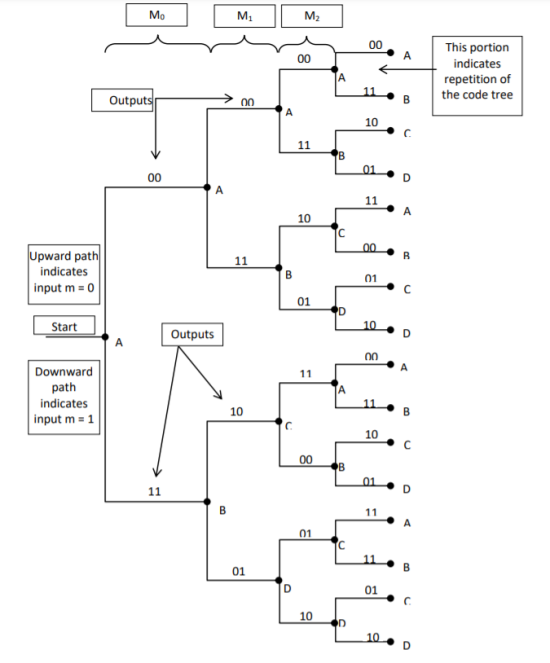
Fig 7. Code Tree Representation
3. Code trellis representation
- Code trellis is the more compact representation of the code tree. In the code tree there are four states (or nodes). Every state goes to some other state depending upon the input message bit.
- Code trellis represents the single and unique diagram for such steady state transitions. The Figure below shows the code trellis diagram.
- The nodes on the left denote four possible current states and those on the right represents next state. The solid transition line represents for input message m0 = 0 and dashed line represents input message m0 = 1.
- Along with each transition line, the encoder output x1 x2 is represented during that transition.
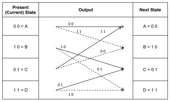
Fig 8. Code Trellis
Advantages of convolutional codes
- The convolutional codes operate on smaller blocks of data. Hence decoding delay is small.
- The storage hardware required is less.
Disadvantages of convolutional codes
- Due to complexity, the convolutional codes are difficult to analyze.
- These codes are not developed much as compared to block codes.
Key takeaway
Comparison between Linear Block codes and Convolutional codes
S.No | Linear Block Codes | Convolutional codes |
1 | Block codes are generated by   | Convolutional codes are generated by convolution between message sequencing and generating sequence. |
2 | For a block of message bits, encoded block (code vector) is generated | Each message bits is encode separately. For every message bit, two or more encoded bits are generated. |
3. | Coding is block by block. | Coding is bit by bit |
4. | Syndrome decoding is used for most likelihood decoding. | Viterbi decoding is ued for most likelihood decoding. |
5. | Generator matrices, parity check matrices and syndrome vectors are used for analysis. | Code tree, code trlls and state diagrams are used for analysis. |
6. | Generating polynomial and generator matrix are used to get code vectors. | Generating sequences are used to get code vectors. |
7. | Error correction and detection capability depends upon minimum distance  | Error correction and detection capability depends upon free distance  |
The Viterbi Algorithm (VA) finds a maximum likelihood (ML) estimate of a transmitted code sequence c from the corresponding received sequence r by maximizing the probability p(r|c) that sequence r is received conditioned on the estimated code sequence c. Sequence c must be a valid coded sequence. The Viterbi algorithm utilizes the trellis diagram to compute the path metrics. The channel is assumed to be memory less, i.e. the noise sample affecting a received bit is independent from the noise sample affecting the other bits. The decoding operation starts from state ‘00’, i.e. with the assumption that the initial state of the encoder is ‘00’.
With receipt of one noisy codeword, the decoding operation progresses by one step deeper into the trellis diagram. The branches, associated with a state of the trellis tell us about the corresponding codewords that the encoder may generate starting from this state. Hence, upon receipt of a codeword, it is possible to note the ‘branch metric’ of each branch by determining the Hamming distance of the received codeword from the valid codeword associated with that branch. Path metric of all branches, associated with all the states are calculated similarly.
Now, at each depth of the trellis, each state also carries some ‘accumulated path metric’, which is the addition of metrics of all branches that construct the ‘most likely path’ to that state. As an example, the trellis diagram of the code shown in Fig. 6.35.1, has four states and each state has two incoming and two outgoing branches. At any depth of the trellis, each state can be reached through two paths from the previous stage and as per the VA, the path with lower accumulated path metric is chosen. In the process, the ‘accumulated path metric’ is updated by adding the metric of the incoming branch with the ‘accumulated path metric’ of the state from where the branch originated. No decision about a received codeword is taken from such operations and the decoding decision is deliberately delayed to reduce the possibility of erroneous decision. The basic operations which are carried out as per the hard-decision Viterbi Algorithm after receiving one codeword are summarized below:
a) All the branch metrics of all the states are determined;
b) Accumulated metrics of all the paths (two in our example code) leading to a state are calculated taking into consideration the ‘accumulated path metrics’ of the states from where the most recent branches emerged;
c) Only one of the paths, entering into a state, which has minimum ‘accumulated path metric’ is chosen as the ‘survivor path’ for the state (or, equivalently ‘node’);
d) So, at the end of this process, each state has one ‘survivor path’. The ‘history’ of a survivor path is also maintained by the node appropriately ( e.g. By storing the codewords or the information bits which are associated with the branches making the path)
e) Steps a) to d) are repeated and decoding decision is delayed till sufficient number of codewords has been received. Typically, the delay in decision making = Lx k codewords where L is an integer, e.g. 5 or 6. For the code in Fig. Above, the decision delay of 5x3 = 15 codewords may be sufficient for most occasions. This means, we decide about the first received codeword after receiving the 16th codeword. The decision strategy is simple.
Upon receiving the 16th codeword and carrying out steps a) to d), we compare the ‘accumulated path metrics’ of all the states ( four in our example) and chose the state with minimum overall ‘accumulated path metric’ as the ‘winning node’ for the first codeword. Then we trace back the history of the path associated with this winning node to identify the codeword tagged to the first branch of the path and declare this codeword as the most likely transmitted first codeword. The above procedure is repeated for each received codeword hereafter. Thus, the decision for a codeword is delayed but once the decision process starts, we decide once for every received codeword. For most practical applications, including delay-sensitive digital speech coding and transmission, a decision delay of Lx k codewords is acceptable.
Soft-Decision Viterbi Algorithm
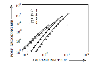
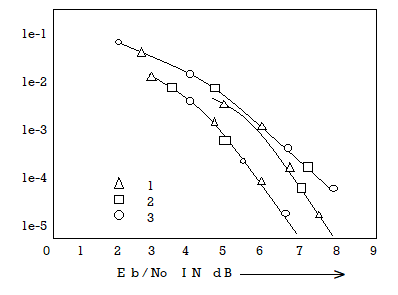
In soft-decision decoding, the demodulator does not assign a ‘0’ or a ‘1’ to each received bit but uses multi-bit quantized values. The soft-decision Viterbi algorithm is very similar to its hard-decision algorithm except that squared Euclidean distance is used in the branch metrics instead of simpler Hamming distance. However, the performance of a soft-decision VA is much more impressive compared to its HDD (Hard Decision Decoding) counterpart The computational requirement of a Viterbi decoder grows exponentially as a function of the constraint length and hence it is usually limited in practice to constraint lengths of K = 9.
Source emcoding is a process in which the output of an information source is converted into a r-ary sequence where r is the number of different symbols used in this transformation process . The functional block that performs this task in a communication system is called source encoder.
The input to the encoder is the symbol sequence emitted by the information source and the output of the encoder is r-ary sequence.
If r=2 then it is called the binary sequence
r=3 then it is called ternary sequence
r=4 then it is called quarternary sequence..
Let the source alphabet S consist of “q” number of source symbols given by S = {S1,S2…….Sq} . Let another alphabet X called the code alphabet consists of “r” number of coding symbols given by
X = {X1,X2………………………Xr}
The term coding can now be defined as the transformation of the source symbols into some sequence of symbols from code alphabet X.
Shannon’s encoding algorithm
The following steps indicate the Shannon’s procedure for generating binary codes.
Step 1:
List the source symbols in the order of non-increasing probabilities
S = {S1,S2,S3……………………Sq} with P = {P1,P2,P3…………………..Pq}
P1 ≥P2 ≥P3 ≥………………….Pq
Step 2
Compute the sequences 
 = P1 +
 = P2 + P1 = P2 +
 P3+P2+P1 = P3 +
….. ……..
 = Pq + Pq-1 +…………+ P2 + P1 = Pq +
Step 3:
Determine the smallest integer value of “li using the inequality
2 li  for all i=1,2,……………………q.
Step 4:
Expand the decimal number  in binary form upto li places neglecting expansion beyond li places.
Step 5:
Remove the binary point to get the desired code.
Example :
Apply Shannon’s encoding (binary algorithm) to the following set of messages and obtain code efficiency and redundancy.
m 1 | m 2 | m 3 | m 4 | m 5 |
1/8 | 1/16 | 3/16 | ¼ | 3/8 |
Step 1:
The symbols are arranged according to non-incraesing probabilities as below:
m 5 | m 4 | m 3 | m 2 | m 1 |
3/8 | ¼ | 3/16 | 1/16 | 1/8 |
P 1 | P 2 | P 3 | P 4 | P 5 |
Step 2:
The following sequences of  are computed
 = 0
= 0
 P1 +
P1 +  = 3/8 + 0 = 0.375
 = P2 +
  = ¼ + 0.375 = 0.625
 = P3 +
  = 3/16 + 0.625 = 0.8125
 = P4 +
  = 1/16 + 0.8125 = 0.9375
 = P5 +
  = 1/8 + 0.9375 = 1
Step 3:
The smallest integer value of li is found by using
2 li ≥ 1/Pi
For i=1
2 l1 ≥ 1/P1
2 l1 ≥ 1/3/8 = 8/3 = 2.66
The samllest value ofl1 which satisfies the above inequality is 2 therefore l1 = 2.
For i=2 2 l2 ≥ 1/P2 Therefore 2 l2 ≥ 1/P2
2 l2 ≥ 4 therefore l2 = 2
For i =3 2 l3 ≥ 1/P3 Therefore 2 l3 ≥ 1/P3 2 l3 ≥ 1/ 3/16 = 16/3 l3 =3
For i=4 2 l4 ≥ 1/P4 Therefore 2 l4 ≥ 1/P4
2 l4 ≥ 8 Therefore l4 = 3
For i=5
2 l5 ≥ 1/P5 Therefore
2 l5 ≥ 16 Therefore l5=4
Step 4:
The decimal numbers  are expanded in binary form upto li places as given below.
 = 0
= 0
 0.375
0.375
0.375 x2 = 0.750 with carry 0
0.75 x 2 = 0.50 with carry 1
0.50 x 2 = 0.0 with carry 1
Therefore
(0.375) 10 = (0.11)2
 = 0.625
0.625 X 2 = 0.25 with carry 1
0.25 X 2 = 0.5 with carry 0
0.5 x 2 = 0.0 with carry 1
(0.625) 10 = (0.101)2
 = 0.8125
0.8125 x 2 = 0.625 with carry 1
0.625 x 2 = 0.25 with carry 1
0.25 x 2 = 0. 5 with carry 0
0.5 x 2 = 0.0 with carry 1
(0.8125) 10 = (0.1101)2
 = 0.9375
0.9375 x 2 = 0.875 with carry 1
0.875 x 2 = 0.75 with carry 1
0.75 x 2 = 0.5 with carry 1
0.5 x 2 = 0.0 with carry 1
(0.9375) 10 = (0.1111)2
 = 1
= 1
Step 5:
 and l1 = 2 code for S1 ----00
 =(0.011) 2 and l2 =2 code for S2 ---- 01
 = (.101)2 and l3 =3 code for S3 ------- 101
 = (.1101)2 and l4 =3 code for S ----- 110
 = (0.1111)2 and l5 = 4 code for s5 --- 1111
The average length is computed by using
L = 
= 3/8 x 2 + ¼ x 2 + 3/16 x 3 + 1/8 x 3 + 1/16 x 4
L= 2.4375 bits/msg symbol
The entropy is given by
H(s) = 3/8 log (8/3) + ¼ log 4 + 3/16 log 16/3 + 1/8 log 8 + 1/16 log 16
H(s) =2.1085 bits/msg symbol.
Code efficiency is given by
c = H(s)/L = 2.1085/2.4375 = 0.865
Percentage code effeciency = 86.5% c
Code redundancy
R c = 1 - c = 0.135 or 13.5%.
Code trellis representation
- Code trellis is the more compact representation of the code tree. In the code tree there are four states (or nodes). Every state goes to some other state depending upon the input message bit.
- Code trellis represents the single and unique diagram for such steady state transitions. The Figure below shows the code trellis diagram.
- The nodes on the left denote four possible current states and those on the right represents next state. The solid transition line represents for input message m0 = 0 and dashed line represents input message m0 = 1.
- Along with each transition line, the encoder output x1 x2 is represented during that transition.
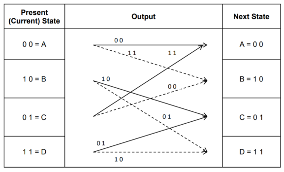
Fig 9 Code Trellis
Advantages of convolutional codes
- The convolutional codes operate on smaller blocks of data. Hence decoding delay is small.
- The storage hardware required is less.
Disadvantages of convolutional codes
- Due to complexity, the convolutional codes are difficult to analyze.
- These codes are not developed much as compared to block codes.
- Pseudo-Noise (PN) also known Pseudo Random Binary Sequence (PRBS).
- A Pseudo-Noise code (PN-code) or Pseudo Random Noise Code (PRN code) is a spectrum which generated deterministically by random sequence.
- PN sequence is random occurance of 0’s and 1’s bit stream.
- Directly sequence spread spectrum (DS-SS) system is most popular sequence in DS-SS system bits of PN sequence is known as chips and inverse of its period is known as chip rate.
In frequency hopping spread spectrum (FH-SS) sequence, channel number are pseudo random sequences and hop rate are inverse of its period.
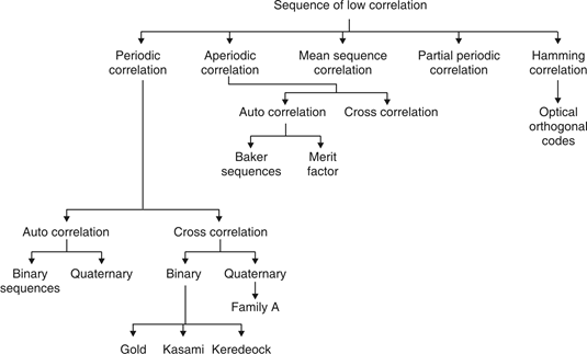
Fig. 10: Overview of PN sequence
Properties
(i) Balance property:
Total no. Of 1’s is more than no. Of 0’s in maximum length sequence.
(ii) Run property 1’s and 0’s stream shows length sequence, every fraction relate some meaning.
Rum | Length |
1/2 | 1 |
1/4 | 2 |
1/8 | 3 |
(iii) Correlation property:
If compared sequences are found similar then it is auto correlation.
If compared sequences are found mismatched then it is cross correlation.
Let (K) and y (K) are two sequences then correlation R (m) will be:

Correlation R (m) in pattern of digital bit sequence will be:

y1 = P1 q1
y1 = 0 if P1 q1
y1 = 1 if P1 = q1
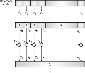
Fig. 11: Correlator
Fig. Shows Pi is a sequence which shifts through K bit shift register. K is length of correlate. Output achieved by K XNOR gate after comparison.
(iv) Shift and add:
By using X-OR gate, shift sequence modulo-2 added to upshifted sequence.
PN sequence generation methodologies :
(i) Using shift register with feedback.
(ii) Series parallel method for high speed PN generation.
(iii) Avoiding zero state.
(iv) Barker sequence.
(v) Kasami sequence.
(vi) Gold sequence.
Direct Sequence Spread Spectrum (DSSS) using BPSK modulation, so the first reversing switch introduces 180 degree phase reversals according to a pseudo-random code, while the second introduces the same reversals to reconstitute the original, narrow-band signal. The output is a “recompressed” narrow-band signal.
DSSS is a spread spectrum modulation technique used for digital signal transmission over airwaves. It was originally developed for military use, and employed difficult-to-detect wideband signals to resist jamming attempts.
It is also being developed for commercial purposes in local and wireless networks.
The stream of information in DSSS is divided into small pieces, each associated with a frequency channel across spectrums. Data signals at transmission points are combined with a higher data rate bit sequence, which divides data based on a spreading ratio. The chipping code in a DSSS is a redundant bit pattern associated with each bit transmitted.
This helps to increase the signal's resistance to interference. If any bits are damaged during transmission, the original data can be recovered due to the redundancy of transmission.
The entire process is performed by multiplying a radio frequency carrier and a pseudo-noise (PN) digital signal. The PN code is modulated onto an information signal using several modulation techniques such as quadrature phase-shift keying (QPSK), binary phase-shift keying (BPSK), etc. A doubly-balanced mixer then multiplies the PN modulated information signal and the RF carrier. Thus, the TF signal is replaced with a bandwidth signal that has a spectral equivalent of the noise signal. The demodulation process mixes or multiplies the PN modulated carrier wave with the incoming RF signal. The result produced is a signal with a maximum value when two signals are correlated. Such a signal is then sent to a BPSK demodulator. Although these signals appear to be noisy in the frequency domain, bandwidth provided by the PN code permits the signal power to drop below the noise threshold without any loss of information.
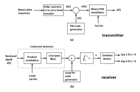
Fig 12(a) Transmitter (b) Receiver of DS-SS Technique
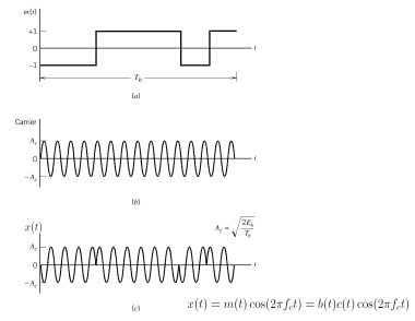
Fig 13 Wave forms for DSSS
Key takeaway
- In practice, the transmitter and receiver of Figures shown above are followed. In the transmitter spectrum spreading is performed prior to phase modulation. Also phase demodulation is done first and then despreading is done second, in the receiver.
- In the model of DS spread spectrum BPSK system used for analysis, the order of these two operations is interchanged. In the transmitter, BPSK is done first and spectrum spreading is done subsequently. Similarly, at the receiver also, spectrum de spreading is done first and then phase demodulation is done second.
- This is possible, because the spectrum spreading and BPSK are both linear operations.

Fig. 14: General spread spectrum structure
- Spread spectrum is specially used for wireless communication signal spreading. Transmitted signals frequency varies deliberately.
- Frequency hopping and direct sequence are two popular spread spectrums.
- In frequency hopping, signals are broadcast over any random series of frequency while in direct sequence each bit is in order of multiple bit of transmitting signal it uses chipping code.
Frequency Hoping Spread Spectrum (FHSS)
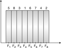
Fig.15: Channel assignment
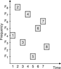
Fig.16: Channel use
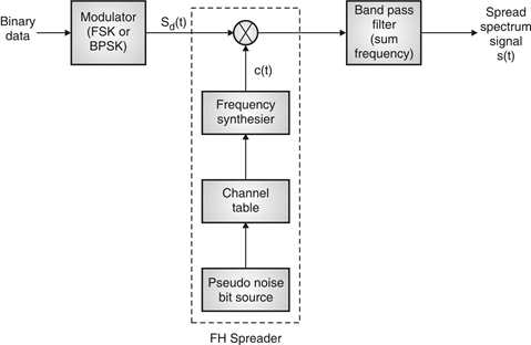
Fig. 17: FHSS (Transmitter)
In FHSS, according to PN sequence RF carries frequency used to get change.
FHSS has two types
1. Fast hopped FHSS.
2. Slow hopped FHSS.
Hopping is done with faster rate compared to bit rate in fast hopped FHSS while slow rate compared to message bit rate in slow hopped FHSS.
FHSS systems rely on changes in RF carrier frequencies which turn into burst errors.
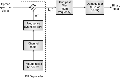
Fig. 18: FHSS (Receiver)
a) Reduced interference: In SS systems, interference from undesired sources is considerably reduced due to the processing gain of the system.
b) Low susceptibility to multi-path fading: Because of its inherent frequency diversity properties, a spread spectrum system offers resistance to degradation in signal quality due to multi-path fading. This is particularly beneficial for designing mobile communication systems.
c) Co-existence of multiple systems: With proper design of pseudo-random sequences, multiple spread spectrum systems can co-exist.
d) Immunity to jamming: An important feature of spread spectrum is its ability to withstand strong interference, sometimes generated by an enemy to block the communication link. This is one reason for extensive use of the concepts of spectrum spreading in military communications.
A specific example of the use of spread spectrum technology is the North American Code Division Multiple Access (CDMA) Digital Cellular (IS-95) standard. The CDMA employed in this standard uses a spread spectrum signal with 1.23-MHz spreading bandwidth. Since in a CDMA system every user is a source of interference to other users, control of the transmitted power has to be employed (due to near-far problem). Such control is provided by sophisticated algorithms built into control stations.
The standard also recommends use of forward error-correction coding with interleaving, speech activity detection and variable-rate speech encoding. Walsh code is used to provide 64 orthogonal sequences, giving rise to a set of 64 orthogonal ‘code channels’. The spread signal is sent over the air interface with QPSK modulation with Root Raised Cosine (RRC) pulse shaping. Other examples of using spread spectrum technology in commercial applications include satellite communications, wireless LANs based on IEEE 802.11 standard etc.
Satellite systems, mobile networks
Satellites are used to transfer information from one place to another using communication satellite on Earth’s orbit. Satellite communication began in 1957 and the first artificial satellite launched was Sputnik I by the USSR. The satellite communication can be one way as well. In this case the transmission of signal from the transmitter of first earth satellite and the receiver of the second earth satellite is in one direction.
In two-way communication the information is exchanged between the two earth stations. There are two uplinks and two downlinks required to achieve two ways communication.
The main elements of communication satellite are
a) Uplink
b) Transponders
c) Downlink
The block diagram of satellite communication is shown below. A communication satellite is basically a R.F repeater.
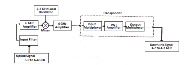
Fig 19. Block Diagram of Satellite Communication
The uplink frequencies used are of range 5.9GHz-6.4GHz these frequencies are converted to lower frequencies and amplified. The mixers and local oscillators are used to convert the higher frequency uplink signals to lower frequency signals. The com satellite receives this signal amplifies it and then transmits it so that there is no interference in the uplink and down link signals.
The transponders provide the medium for two-way communication. The downlink frequency used for transmission is from the range of 3.7GHz to 4.2GHz. The number of transponders per satellite depends upon the task which the satellite needs to do. For television broadcast two transponders are used in a satellite.
Advantages
The advantages of satellite communication are
- They are easy to install.
- The communication can be set up in every part of earth with the help of satellites.
- The network is controlled by the user.
- The elasticity of these circuits is excellent
Applications
The applications of satellite communication are
- Telephone
- Television
- Digital cinema
- Radio broadcasting
- Amateur radio
- Internet access
- Military
- Disaster Management
Wireless LAN IEEE 802.11
IEEE 802.11 is a set of standards carrying out wireless local area network (WLAN) computer communication in the 2.4, 3.6 and 5 GHz frequency bands. They are created and maintained by the IEEE LAN/MAN Standards Committee (IEEE 802)
802.11a — an extension to 802.11 that applies to wireless LANs and provides up to 54-Mbps in the 5GHz band. 802.11a uses an orthogonal frequency division multiplexing encoding scheme rather than FHSS or DSSS.
802.11b — an extension to 802.11 that applies to wireless LANS and provides 11 Mbps transmission in the 2.4 GHz band. 802.11b uses only DSSS. 802.11b was a 1999 ratification to the original 802.11 standard, allowing wireless functionality comparable to Ethernet.
802.11e — a wireless draft standard that defines the Quality of Service support for LANs, and is an enhancement to the 802.11a and 802.11b wireless LAN (WLAN) specifications. 802.11e adds QoS features and multimedia support to the existing IEEE 802.11b and IEEE 802.11a wireless standards, while maintaining full backward compatibility with these standards.
802.11g — applies to wireless LANs and is used for transmission over short distances at up to 54-Mbps in the 2.4 GHz bands.
802.11n — 802.11n builds upon previous 802.11 standards by adding multiple-input multiple-output. The additional transmitter and receiver antennas allow for increased data throughput through spatial multiplexing and increased range by exploiting the spatial diversity through coding schemes like Alamouti coding. The real speed would be 100 Mbit/s (even 250 Mbit/s in PHY level), and so up to 4-5 times faster than 802.11g.
- CDMA stands for Code Division Multiple Access. CDMA is a technique for spread spectrum multiple access.
- Data signals are XOReD with pseudorandom code and then transmitted over a channel.
- Different codes are used to modulate their signals, selection of code to modulate is important aspect as it relates with performance of system.
- In CDMA, single channel uses entire bandwidth and it does not share time as all stations transmit data simultaneously. Due to this CDMA differ from FDMA and TDMA.
- Let us assume we have 4 different stations A, B, C and D. All 4 stations connected to same channel. Data from station A is d1, B is d2, C is d3 and D is d4 similarly code assigned to A is C1, B is C2, C is C3 and D is C4.
- To transmit data, all 4 stations have multiplication strategy i.e. either code multiply by itself. It results in 4 stations or code multiply results in 4 stations or code multiply results in 4 station of code multiply by another, it results in zero station.
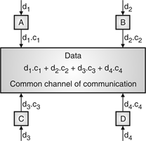
Fig. 20: Communication of station with code
- If station C and station D are talking to each other, D wants to listen whatever C is saying. It multiplies data on channel by C3 of station C.
- As C3 C3 is 4 and rest of combination i.e. C1 C3, C2 C3 and C4 C3 are all zero.
- Every station has some code, which is sequence of numbers known as chips.
- Sequence should be selected in proper manner to get appropriate codes. Orthogonal sequence has some properties:
- Multiplication of sequence by a scalar.
- Inner product of two equal sequences.
- Inner product of two different sequences.
- Sequence generation uses Walsh table to generate chip sequence.
- CDMA systems spread symbols. Before spreading symbols it uses distinctive code before transmission.
- On receiver side all symbols accepted by dispreading with help of correlating symbols. A signal which does not required are neither correlate nor de-spread to accept.
- CDMA signals are sequence of 0’s and 1’s and sequences are generated from code. Symbol per second means original data rate and chip rates means code chipping rate.
- Every code belongs to distinct set of data.
- CDMA allows space, time frequency signals transmission. Different coding method used in CDMA are:
(a) Autocorrelation codes
(i) Barker code.
(ii) Pseudo-noise code.
(b) Other important codes
(i) Orthogonal codes.
(ii) Walsh codes.
(iii) Scrambling codes.
(iv) Channelization codes.
(v) Carrier modulation codes.
References:
1. P Ramkrishna Rao, Digital Communication, McGraw-Hill Publication
2. J.G. Proakis, Digital Communication.
3. S. Haykin, Communication Systems
4. Leon W. Couch: Analog/Digital Communication, 5thEdition, PHI,2008