Unit - 1
Introduction and Modeling of control system
Automation is the use of control systems and information technologies to reduce the need for human work in the production of goods and services. In the scope of industrialization, automation is a step beyond mechanization. Whereas mechanization provided human operators with machinery to assist them with the muscular requirements of work, automation greatly decreases the need for human sensory and mental requirements as well.
Automation Control System - system that is able to control a process with minimal human assistance or without manual and have the ability to initiate, adjust, action show or measures the variables in the process and stop the process in order to obtain the desired output.
The main objective of Automation Control System used in the industry are:
- To increase productivity
- To improve quality of the product
- Control production cost
Types of Automation in The Industry
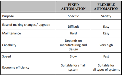
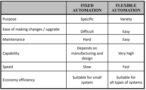
a) Permanent/Fixed Automation - This control system is designed to perform a specific task. Functions of control circuit is fixed and permanent. It will be complicated if we want to do another task apart from the existing task
b) Programmable /Flexible Automation - Programmable automation or flexible automation is a complex control system that can perform several tasks. Functions of control circuit programmed by the user and can be modified. When the task to be performed by machines changed, changes only need to be done by making modifications to the machine control program.
Comparison between Fixed and Flexible Automation System
Advantages
- Replacing human operators in tasks that involve hard physical work.
- Replacing humans in tasks done in dangerous environments (i.e. fire, space, volcanoes, nuclear facilities, underwater, etc.)
- Performing tasks that are beyond human capabilities of size, weight, speed, endurance, etc.
- Economy improvement: Automation may improve in economy of enterprises, society or most of humanity. For example, when an enterprise invests in automation, technology recovers its investment; or when a state or country increases its income due to automation like Germany or Japan in the 20th Century.
- Reduces operation time and work handling time significantly.
The dynamics of the system can be controlled by the feedback by adjusting the location of poles. In this section we will see how the location of poles effect the dynamics of the system.
Let us consider a system which has open loop transfer function of G(s) defined as
G(s) =  (1)
(1)
Let K =  /
/
 = 1/
= 1/
The poles for the above system lie at s= - and
and  =1/
=1/ is time constant.
The dc gain of the system is given by G(0) = K =  /
/
For closed loop system the transfer function is given by
 (2)
(2)
 =
= 
 =
=  /(1+K)
The above equation shows that due to feedback the system pole shifts from - to (–
to (– +K’). Due to this change the dynamic response of the system is also affected. For studying the dynamic response, we assume that the input to the system is an impulse.
r(t) =  (t)
(t)
And it can also be written as
R(s) = 1
Taking inverse Laplace transform of equation 1 we get
For open loop system
c(t) = K’
Taking inverse Laplace transform of equation 2 we get
For closed loop system
c(t) = K’
The system dynamic response decays in both the open system as well as closed loop system. The closed loop system time constant is  =
=  /(1+K) so its response decays faster than open loop system by factor of (1+K).
Key takeaway
The dynamics of the system can be controlled by the feedback by adjusting the location of poles.
The closed loop system time constant is  =
=  /(1+K) so its response decays faster than open loop system by factor of (1+K).
The representation of relays and contactors in the electrical circuit diagram is identical, as their operating principle.
i) Relays are used to switch relatively small output and current.
Ii) Contactor to switch relatively large output and currents.
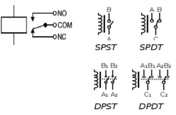
A relay is an electrically operated switch/electromagnetically actuated switch. Current flowing through the coil of the relay creates a magnetic field which attracts a lever and changes the switch contacts. The coil current can be ON or OFF so relays have two switch positions and most have double throw (changeover) switch contacts.
Relays are usually SPDT (Single Pole Double Throw) or DPDT (Double Pole Double Throw) but they can have many more sets of switch contacts.
Poles: the number of sets of contacts
Throw: The number of positions or combinations (open or close) the contacts have.
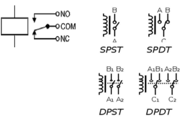
A simple electromagnetic relay consists of a coil of wire wrapped around a soft iron core, an iron yoke which provides a low reluctance path for magnetic flux, a movable iron armature, and one or more sets of contacts. The armature is hinged to the yoke and mechanically linked to one or more sets of moving contacts. It is held in place by a spring so that when the relay is de-energized there is an air gap in the magnetic circuit. When an electric current is passed through the coil it generates a magnetic field that activates the armature, and the consequent movement of the movable contact(s) either makes or breaks (depending upon construction) a connection with a fixed contact. If the set of contacts was closed when the relay was de-energized, then the movement opens the contacts and breaks the connection, and vice versa if the contacts were open. When the current to the coil is switched off, the armature is returned by a force, approximately half as strong as the magnetic force, to its relaxed position. Usually this force is provided by a spring, but gravity is also used commonly in industrial motor starters. Most relays are manufactured to operate quickly. In a low-voltage application this reduces noise; in a high voltage or current application it reduces arcing.
A contactor is an electrically controlled switch used for switching a power circuit, similar to a relay except with higher current ratings. Contactors are used to control electric motors, lighting, heating, capacitor banks, and other electrical loads.
A contactor has three components. The contacts are the current carrying part of the contactor. This includes power contacts, auxiliary contacts, and contact springs. The electromagnet provides the driving force to close the contacts. The enclosure is a frame housing the contact and the electromagnet.
A basic contactor will have a coil input (which may be driven by either an AC or DC supply depending on the contactor design). The coil may be energized at the same voltage as the motor, or may be separately controlled with a lower coil voltage better suited to control by programmable controllers and lower-voltage pilot devices.
Unlike general-purpose relays, contactors are designed to be directly connected to high-current load devices. Relays tend to be of lower capacity and are usually designed for both normally closed and normally open applications. Devices switching more than 15 amperes or in circuits rated more than a few kilowatts are usually called contactors. Apart from optional auxiliary low current contacts, contactors are almost exclusively fitted with normally open contacts. Unlike relays, contactors are designed with features to control and suppress the arc produced when interrupting heavy motor currents. When current passes through the electromagnet, a magnetic field is produced, which attracts the moving core of the contactor.
The electromagnet coil draws more current initially, until its inductance increases when the metal core enters the coil. The moving contact is propelled by the moving core; the force developed by the electromagnet holds the moving and fixed contacts together. When the contactor coil is de-energized, gravity or a spring returns the electromagnet core to its initial position and opens the contacts.
A mathematical model of a dynamic system is defined as a set of equations that represents the dynamics of the system accurately. A mathematical model is not unique for a given system. It is possible to improve the accuracy of a mathematical model by increasing its complexity.
Linear system: A system is called linear if the principle of superposition applies.
Hence, for the linear system, the response to several inputs can be calculated by treating one input at a time and adding the results.
The motion that takes place along a straight line is called translational motion. The forces that resist motion are -
Translational mechanical system:
Inertia: A body with mass ‘N’ acceleration ‘a’ will produce inertia fm(t)= malt N’ acceleration ‘a’ will produce inertia
fm(t)= M a(t)
In terms of velocity
Fm(t) = M dv(t)/dt
In terms of displacement
Fm(t)= Md2/dt2µt
Damping force: The damping force is proportional to velocity for vis case function
F0(t) = B(t) = B dx(t) /dt
B Damping coefficient N/M sec
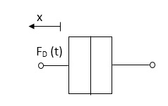
Fig 1. Damping force
Spring force: A spring stores potential energy. The releasing force of a string is proportional to the displacement.
Fk(t)  x(t)
x(t)
Fk(t) = k x (t)
Fk(t) = k 
K = string constant N/m.
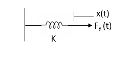
Fig 2. Spring force
Rotational mechanical system:
The motion of a body about a fixed axis is called as Rotational motion. The types of torques which can resist the motion are
Inertial Torque: - The inertial torque is the product of moment of inertia I and angular acceleration.
TI(t) = J (t)
(t)
TI(t) = Jd/dt w(t)
TI(t) = Jd2ø(t)/dt2(N-m)
W (t) – Angular velocity
Ø(t) = Angular displacement
Damping Torque: - it is product of damping efficient B and angular velocity w
T0 (t) = B w(t)
T0(t) = B d/dt ø(t)
Spring Torque: - It is the product of torsional stiffness and angular displacement
Tø(t) = k ø(t)
K = N.m/rad

Fig 3. Spring Torque
D’Alembert’s Principle
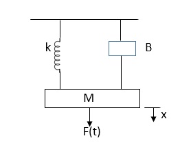
For anybody, the algebraic sum of externally applied forces and the forces resisting motion in any given direction is zero.
Ex.
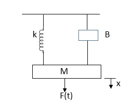
In above figure applying D’Alemberts principle to write the equation of motion
As force f(t) acts downwards all other forces (of k,B,x) acts Opposite to it to considering f(t) as the and all other forces negative.
F(t)+fm (t) + fD(t) +fx(t) =0
f(t)- M d2x(t)/dt2+B dx(t)/dt +x(t)
Example
Draw the free body diagram and write the differential equation for system below.
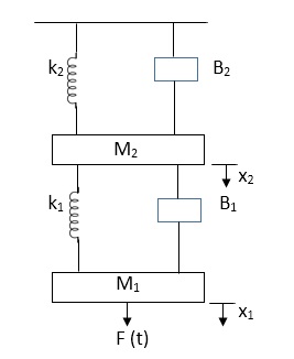
Fig 4. Mechanical system
Soln: The free body diagram for M1 will be
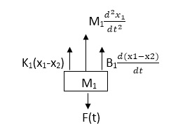
Fig 5. FBD
F(t) = M1 d2/dt2x1+ B1 d/dt (x1-x2)+ k1(x1-x2)
Similarly for M2we have
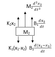
Fig 6. FBD
K1(x1-x2) + B1d/dt(x1-x2) = k2x2+M2d2/dt2+B2dx2/dt
Key takeaway
Analogy Between Electrical and Mechanical System:
Force -voltage | Force -current | Mechanical Translatory | Mechanical Rotational |
1.Voltage (v) | Current | Force (f) | Torque (T) |
2.Charge(q) | Flux (ø) | Displacement(x) | Angular Displacement(ø) |
3.current. | Voltage | Velocity v(t) | Angular velocity(w) |
4.Inductance(l) | Capacitance(c) | Mass (m) | Moment of inertia (J) |
5. Resistance(R) | Conductance G= (1/R) | Damping coefficient (B) | Damping Coefficient (B) |
6.Reciprocal of capacitance(1/c) | Inverse of Inductance (1/L) | Stiffness (K) | Stiffness(K) |
It is the ratio of Laplace transform of the output to Laplace transform of input with all initial conditions zero.

Fig 7. System with Transfer Function G(s)
Poles and zero of a Transfer Function:
The transfer function can be represented by the ratio of two polynomials
G (S) = a0sn+a1 sn-1-------+an/b0sm+b1sm-1+-----+bn
a0—an ---- constants
G(S) = K(s+z1) (s+z2) (as2+bs+c)/(S+A) (s+p2) (As2+Bs +c)
K= a0/b0 ( Gain of system)
For poles –They are the values of s for which
G(S)
(S+p1)(S+p2)(AS2 + BS + C) = 0
S= p1, -p2 , -B±B2-4Ac/2A
For ZEROS – They are the values of s for which
G(S) 0
S=-z1, -z2 , -b±b2-4ac/2a
- Location of poles and zeros in s place determines the reliability of the system
- There can be multiple poles and zeros
- The numerator of transfer function when equalized to zero gives zero of system
- The denominator of transfer function which equalized to zero gives poles of system.
Key takeaways
- The numerator of transfer function when equalized to zero gives zero of system.
- The denominator of transfer function which equalized to zero gives poles of system.
Advantages of Block diagram reduction technique:
- Very simple to Construct the Block diagram of complicated electrical & mechanical systems.
- The function of individual element can be visualized form block diagram
- Individual as well as overall performance of the system can be studied by the if shown in Block diag.
- Overall CLTf can be easily calculated by Block diag reduction rules.
Disadvantages of Block diagram reduction technique:
It does not include any information above physical construct of system (completely mathematical approach).
a) Source of energy in generally not shown in the block diag so w.g diff. Block diag can be drawn for the same function
CLTf: -ve feedback
C(s)/R(s)= G(s)/1+G(s)H(s)
CLTF: +ve feedback
C(S)/R(S) = G(S)/1-G(s)H(S)
Rules of Block diagram Algebra:
Block in cascade

Moving summing point after a block

Moving summing point ahead of block

Moving take off point after a block

Moving take off point ahead a block

Eliminating a feedback Loop

Fig 8. Block Diagram Reduction Techniques
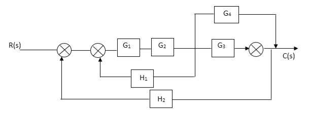
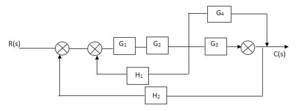
Q. Reduce given B.D to canonical (simple form) and hence obtain the equivalent Tf = c(s)/ R(S)?
Sol: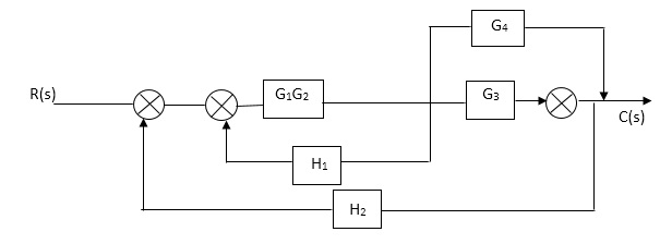


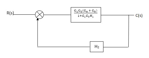
Fig 9. Final reduced block diagram
C(S)/R(S) = (G1G2) (G3+G4)/1+G1G2H1)/1-G1,G2(G3+G4) H2/1+G1G2H1
= G1G2(G3+G4)/1+G1G2H1-G1G2H2(G3+G4)
=G1G2(G3+G4)/1+(H1-H2)(G1G2) (G3+G4)
C(s)/R(S) = G1G2(G3+G4)/1+(H1-H2(G3+G4)) G1 G2
Q) Reduce the Block diagram
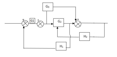
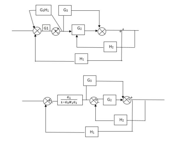
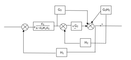
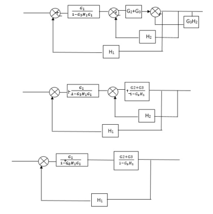
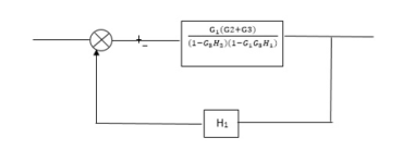
Fig 10. Final Reduced Block diagram
C(s)/R(s)= G1(G3+G2)/(1-G1G3X1) (1-G2X2) H1
= G(G3+G2)/(1-G3G1H1) (1-G2H2) + G1H1(G3+G2)
= G1(G3+G2)/1-63G1H1-G2H2+G1H1(G3+G2H1
=G1(G3+G2)/1-G3H2+G1G2H1(1+G3H2)
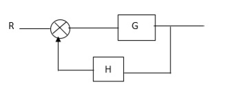
Fig 11. Block Diagram

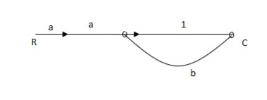
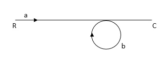
Fig 12. SFG
Q:
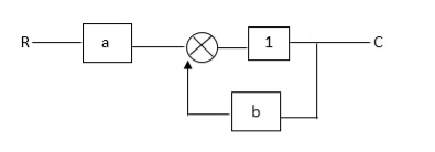
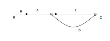
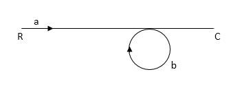
Ra+cb =c
c/R= a/1-b
RULES:
1) The signal travels along a branch in the direction of an arrow.
2) The lip signal is multiplied by the transmittance to obtain the o/p.
3) I/p signal at a node is sum of all the signals entering at that node.
4) A node transmits signal at all branches leaving that node.
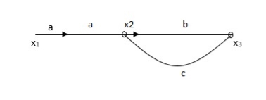
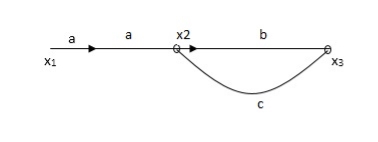
Q. The SFG shown has forward path and singles isolated loop determine overall transmittance relating X3 and X1?
Sol:
X1- I/p node
X2-Intenmediale node
X3- o/p node
Ab- forward path (p)
Bc- 1 loop (L)
At node XQ:
X2 = x1a + x3c [Add i/p signals at node]
At node x3:
x2b =x3
(x1a+x3c) b = x3
X1ab = x3 (1-bc)
X1 = x3 (1-bc)/ab
Ab/(1-bc) = x3/x1
T= p/1-L

X1:- I/p node x2, x3,x4,x5,Qnlexmedili node
X0:- o/p node abdeg:- forward path
Bc, ef :- Loop [isolated]
x2 = ax1+c x3
x3= bx2
x4 = d x3+f x5
x5 = e x4
x6= g x5
x6 = g(e x4) = ge [dx3+ e f x5]
xb = ge [d (bx2) + f (e x4)]
xb = ge [ db (ax1+cx3) + fe (dx3+ fx5)]
xb = ge [db (ax1+cb (ax1+x3) +fe[cdbx2]+
f( e [db (ax1+ cx3)
x2 = ax1 + cb (x2) x4 = d bx2 + f exq
x2 = ax1 + cbx2 = db (d4) + fe/1-cb
x2 = ax1/(1-cb) xy = db x2 + f x6/g
xy = db [ax1]/1-cb + f xb/g
x5 = c db( ax1)/1-cb + efxb/g
xb = gx5
= gedb (ax1)/1-cb + g efxb/g
Xb = gx5
Gedb (ax1)/1-cb + g efxb/g
(1- gef/g) xb = gedb ax1/1-ab
Xb/x1 = gedb a/ (1- ef – bc + beef
Xb/x1 = p/ 1- (L1+L2) + L1 L2 for isolated loops
The feedback systems are having many advantages over the non-feedback system as we have seen earlier. So, some performance parameters can be controlled through this feedback system such as sensitivity, noise etc. Sensitivity is a parameter which forecasts the effectiveness of feedback in reducing the influence of these variations on system performance. [Reference 4]
The output of the open loop system is given by
C(s) = G(s)R(s)
Now due to variation in parameters G(s) changes to [G(s)+G(s)]. The output will now become
C(s)+ C(s) = [G(s)+ G(s)] R(s)
C(s) = G(s)R(s)
For closed loop system the output is given as

Now due to variation in parameters it becomes

The above equation shows that if there is variation in parameters then G(s) is reduced by factor of 1+G(s)H(s). The variation in overall transfer function T(s) due to change in G(s) is defined as sensitivity.

When there is small change in G(s) then sensitivity becomes

 : Sensitivity of T w.r.t G
For closed loop system the sensitivity will be

For open loop system

As T=G
The sensitivity of T w.r.t H is given as

The above equation shows that for large values of GH sensitivity of the feedback system w.r.t H approaches to unity.
Key takeaway
For closed loop system the sensitivity w.r.t G is reduced by a factor of (1+GH) as compared to the open loop system.
The feedback helps to control the disturbances as they generate an error signal. The signal flow graph for closed loop system is given by
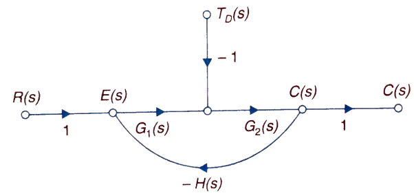
Fig 13. Closed loop system with disturbance signal
 =
= 
Where:
TD(s) = Disturbance signal.
For |G1G2H(s)|>>1 over the range of s
 =
=
The signal flow graph of a system with noise signal N(s) in the feedback path. The gain is given by
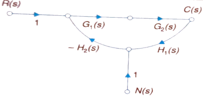
Fig 14. SFG for noise feedback function
 =
= 
For  >>1
>>1
Cn(s) = 
The feedback reduces sensitivity, improves transient response and minimises the effects of disturbance signal in control system.
Servomechanism is also called servo which is a device usually error sensing device connected as a feedback element to correct the action of a mechanism. Here instead of controlling a device by variable input signal, the device is controlled by feedback signal.
The input signal applied to such systems generate the required output which is compared again to the input signal. If the device achieves its desired output, there will be no longer the logical difference between the two signals. Hence, the primary task of servomechanism is to maintain the output of a system at the desired value in the presence of disturbances.
Servomotors: These motors are used in feedback control system. These are also known as control motors. These motors should have low rotor inertia and high speed of response. The servomotors used in the feedback control systems should have linear control signal and rotor speed.
Types of Servomotors:
(a). A.C. Servomotors
(b). D.C. Servomotors
(a). A.C. Servomotors:
A.C servomotor is a two-phase ac induction motor. There are two windings in this motor, one is fixed or reference winding is supplied with a fixed voltage and frequency from a constant voltage source. Second winding is control winding with variable supply voltage of same frequency as reference winding but having a phase displacement of 900 electrical. A flux is induced due to the phase change which cuts the conducting bars of rotor and causes a time varying current, this current produces a time varying flux and reacts with the stator flux causing the rotor to rotate.
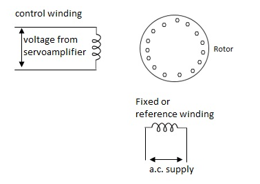
The rotor of A.C. Servomotors are of two types:
(a). Squirrel Cage Rotor
(b). Drag cup type rotor
(a). Squirrel cage rotor: They have high resistance as the rotor is having large length and small diameter. The air gap here is kept small.

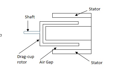
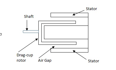
(b). Drag cup type motor: For the drag cup rotor there are two air gaps. For the rotor a cup of non-magnetic conducting material is used. A stationary iron core is placed between the conducting cup to complete the magnetic circuit. The resistance of drag cup type is high and therefore, has high starting torque. Generally aluminium is used for cup.
Torque-speed characteristic:
The torque speed characteristics of the two phase servomotor depends on ratio of reactance to resistance(X/R).
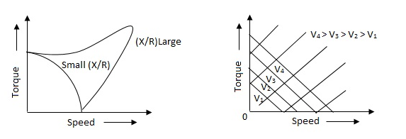
(i). For high ‘R’ and low X, the characteristic is linear and
(ii). For high X and low R, it becomes non-linear.
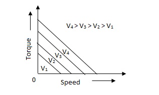
The torque-speed characteristic for various voltage is almost linear.
(b). D.C. Servomotor:
D.C. Servomotor are separately excited or permanent magnet dc servomotors. The armature of D.C. Servomotors is having large resistance and hence torque-speed characteristic is linear.
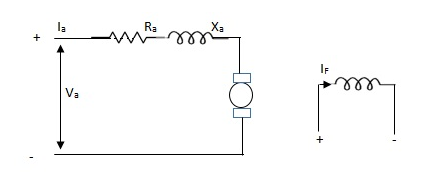
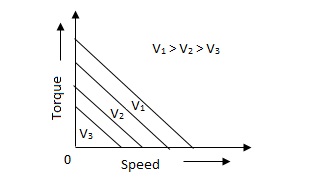
The above graph fig (b), clearly shows that the torque-speed characteristics is a function of control winding voltage as shown below.
T = mw + KVc -- (1)
Where T = Torque developed by motor
w = angular velocity
Vc = control winding voltage
Taking laplace of above equation (1),
T(S) = mS Q(S) + KVc - - (2)
T(S) = JS2Q(S) + FSQ(S) - - (3)
Above equation(3) is the dynamic equation with,
J – moment of inertia
F – coefficient of friction of motor
From equation (2) and (3) the block diagram will be,

Q(S)/Vc = K/Js + F + m - - (4)
Comparison between A.C. Servomotor & D.C. Servomotor
| A.C. Servomotor | D.C. Servomotor |
|
|
|
1. | They are less efficient | They are more efficient |
2. | They have low power output | They have high power output |
3. | No noise so has smooth operation | These motors have noisy operation |
4. | They do not have any radio frequency noise | These motors have brushes so produce radio frequency noise |
5. | They are maintenance free because of no brushes and slip rings | For these motors maintenance is required. |
Control system components
A closed loop control system consists of three basic elements: the feedback element, controller and controlled system. The controller consists of error detector and control elements.

The control element manipulates the actuating signal preferably to different power stage so as to fed to the controlled system. The power stage in control elements is essential for the control signal to drive controlled system. Control elements plays a vital role to get the desired output.
Electrical System
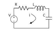
Applying Kirchoff’s voltage Law
V= Ri +Ldi/dt +1/c
V= Rdq/dt + L d2q/dt2+q/c
Now By kirchoff’s current low
I= V/R+ 1/L  + cdv/dt
But V= dø/dt
I= 1/R dø/dt + 1/L ø+cd2ø/dt2
But v= dø/dt
I= 1/R dø/dt+ 1/L. ø+c d2ø/dt2
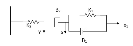
Q.2 For the given mechanical system below draw the analogues system (force. Voltage) & find V0(s)/V1(s)
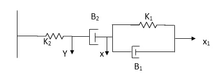
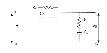
Soln. form the table above we can find the analogues values of system components.
(1) Consider two displacement as two nodes.
(2) If masses are present connect them to reference lines
(3) Connect other elements of system to the nodes
(4) Applying modal analysis to find the system equation.
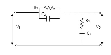
Let Z1 = R2 11 1/c2
=R2*1/c2s/R2+1/c2s
Z1= R2/1+R2c2s
Let Z2 = R1+1/c1s
Z2= 1+R1c1s/c1s
V0(s)/vi(s) = z2/z1+z2
= 1+R1c1s/c1s/R2/1+R2c2s+1+R1c1s/c1s
V0(s)/v0(s) =(c1+R1c1s) (1+R2c2s)/R2c1s+1+sR1c1s2R1R2c1c2
Electromechanical
Armature Controlled dc motor:
In armature controlled motors the time constant is small and hence response is last The efficiency is better than field cannot. The transfer function is calculated below.

Fig 15. Armature controlled d.c servomotor
Applying kVL in armature circuit
V = Raia+ Ldia/dt +E-----(5)
Where
V= applied voltage
Ra = armature resistance
La = Armature inductance
Ia= Armature current
If= field current
E= Induced emf in armature
T= Torque developed by motor
But E= Kb w
E= kbdø/dt --------(6)
W =angular velocity
Kb= back emf
T= k ia-----(7)
The equation for torque will be
T= Jd2ø/dt2+Bdø/dt --------(8)
Taking Laplace of equation (5), (6), (7), (8)
V(S) – E(S) = I1(s) (Ra+sLa)
E(s) = kb s (s)
T(s) = k Ia (s)
T(S)= (s2J+SB) (S)
T(S) = (SJ+B) s (S)
(S)/v(s) k/(Ra+sla) (Js +B) s+ kkbs ------(a)
The Block diagram representation for above equation (a) is shown below.
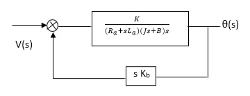
Fig. 16. Block diagram for armature-controlled D.C. Motor
Field controlled D.C. Servomotor:
For field controlled D.C. Motor the ratio L/R is large which means time controller for field circuit is large
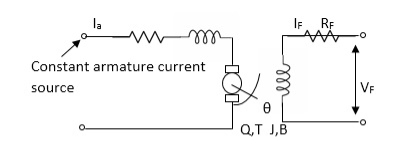
Fig. 17. Circuit for field controlled D.C motor
Applying KVL in field circuit
Vf= Rf If +Lfd If/dt------(10)
T = k øIa
ø If
ø= kfIf
:. T= kkfIa If
Let k, = KIa
T= k’Kf If --------(11)
Dynamic equation for torque is
T= Jd2/dt2 +Bd/dt ------- (12)
Taking Laplace of above equations
Vf(s) = Rf If (c)+SLf If(s) [Rf+SLf]
If= Vf(S)/Rf+ SLf--------(13)
T(s) = (S) [s2J+SB] --------(14)
T(S) = kkfVf(s)/Rf+SLf------ (15)
From equation (14) and (15) we get
(s)/ vf(s) = kkf/s (sJ+B) (Rf+sLf)
The block diagram representation of above equation (16) is shown in figure below

Fig 18. Block diagram for field controlled D.C. Servomotor
References:
1. Automatic Control system (II Edition) – Benjamin C, Kuo, PHI
2. Modern Control System, Drof, Bishop, Wesly Publication
3. Control system Engineering, S.K. Bhattacharya, Pearson Education.
Unit - 1
Introduction and Modeling of control system
Automation is the use of control systems and information technologies to reduce the need for human work in the production of goods and services. In the scope of industrialization, automation is a step beyond mechanization. Whereas mechanization provided human operators with machinery to assist them with the muscular requirements of work, automation greatly decreases the need for human sensory and mental requirements as well.
Automation Control System - system that is able to control a process with minimal human assistance or without manual and have the ability to initiate, adjust, action show or measures the variables in the process and stop the process in order to obtain the desired output.
The main objective of Automation Control System used in the industry are:
- To increase productivity
- To improve quality of the product
- Control production cost
Types of Automation in The Industry
a) Permanent/Fixed Automation - This control system is designed to perform a specific task. Functions of control circuit is fixed and permanent. It will be complicated if we want to do another task apart from the existing task
b) Programmable /Flexible Automation - Programmable automation or flexible automation is a complex control system that can perform several tasks. Functions of control circuit programmed by the user and can be modified. When the task to be performed by machines changed, changes only need to be done by making modifications to the machine control program.
Comparison between Fixed and Flexible Automation System
Advantages
- Replacing human operators in tasks that involve hard physical work.
- Replacing humans in tasks done in dangerous environments (i.e. fire, space, volcanoes, nuclear facilities, underwater, etc.)
- Performing tasks that are beyond human capabilities of size, weight, speed, endurance, etc.
- Economy improvement: Automation may improve in economy of enterprises, society or most of humanity. For example, when an enterprise invests in automation, technology recovers its investment; or when a state or country increases its income due to automation like Germany or Japan in the 20th Century.
- Reduces operation time and work handling time significantly.
The dynamics of the system can be controlled by the feedback by adjusting the location of poles. In this section we will see how the location of poles effect the dynamics of the system.
Let us consider a system which has open loop transfer function of G(s) defined as
G(s) =  (1)
(1)
Let K =  /
/
 = 1/
= 1/
The poles for the above system lie at s= - and
and  =1/
=1/ is time constant.
The dc gain of the system is given by G(0) = K =  /
/
For closed loop system the transfer function is given by
 (2)
(2)
 =
= 
 =
=  /(1+K)
The above equation shows that due to feedback the system pole shifts from - to (–
to (– +K’). Due to this change the dynamic response of the system is also affected. For studying the dynamic response, we assume that the input to the system is an impulse.
r(t) =  (t)
(t)
And it can also be written as
R(s) = 1
Taking inverse Laplace transform of equation 1 we get
For open loop system
c(t) = K’
Taking inverse Laplace transform of equation 2 we get
For closed loop system
c(t) = K’
The system dynamic response decays in both the open system as well as closed loop system. The closed loop system time constant is  =
=  /(1+K) so its response decays faster than open loop system by factor of (1+K).
Key takeaway
The dynamics of the system can be controlled by the feedback by adjusting the location of poles.
The closed loop system time constant is  =
=  /(1+K) so its response decays faster than open loop system by factor of (1+K).
The representation of relays and contactors in the electrical circuit diagram is identical, as their operating principle.
i) Relays are used to switch relatively small output and current.
Ii) Contactor to switch relatively large output and currents.
A relay is an electrically operated switch/electromagnetically actuated switch. Current flowing through the coil of the relay creates a magnetic field which attracts a lever and changes the switch contacts. The coil current can be ON or OFF so relays have two switch positions and most have double throw (changeover) switch contacts.
Relays are usually SPDT (Single Pole Double Throw) or DPDT (Double Pole Double Throw) but they can have many more sets of switch contacts.
Poles: the number of sets of contacts
Throw: The number of positions or combinations (open or close) the contacts have.
A simple electromagnetic relay consists of a coil of wire wrapped around a soft iron core, an iron yoke which provides a low reluctance path for magnetic flux, a movable iron armature, and one or more sets of contacts. The armature is hinged to the yoke and mechanically linked to one or more sets of moving contacts. It is held in place by a spring so that when the relay is de-energized there is an air gap in the magnetic circuit. When an electric current is passed through the coil it generates a magnetic field that activates the armature, and the consequent movement of the movable contact(s) either makes or breaks (depending upon construction) a connection with a fixed contact. If the set of contacts was closed when the relay was de-energized, then the movement opens the contacts and breaks the connection, and vice versa if the contacts were open. When the current to the coil is switched off, the armature is returned by a force, approximately half as strong as the magnetic force, to its relaxed position. Usually this force is provided by a spring, but gravity is also used commonly in industrial motor starters. Most relays are manufactured to operate quickly. In a low-voltage application this reduces noise; in a high voltage or current application it reduces arcing.
A contactor is an electrically controlled switch used for switching a power circuit, similar to a relay except with higher current ratings. Contactors are used to control electric motors, lighting, heating, capacitor banks, and other electrical loads.
A contactor has three components. The contacts are the current carrying part of the contactor. This includes power contacts, auxiliary contacts, and contact springs. The electromagnet provides the driving force to close the contacts. The enclosure is a frame housing the contact and the electromagnet.
A basic contactor will have a coil input (which may be driven by either an AC or DC supply depending on the contactor design). The coil may be energized at the same voltage as the motor, or may be separately controlled with a lower coil voltage better suited to control by programmable controllers and lower-voltage pilot devices.
Unlike general-purpose relays, contactors are designed to be directly connected to high-current load devices. Relays tend to be of lower capacity and are usually designed for both normally closed and normally open applications. Devices switching more than 15 amperes or in circuits rated more than a few kilowatts are usually called contactors. Apart from optional auxiliary low current contacts, contactors are almost exclusively fitted with normally open contacts. Unlike relays, contactors are designed with features to control and suppress the arc produced when interrupting heavy motor currents. When current passes through the electromagnet, a magnetic field is produced, which attracts the moving core of the contactor.
The electromagnet coil draws more current initially, until its inductance increases when the metal core enters the coil. The moving contact is propelled by the moving core; the force developed by the electromagnet holds the moving and fixed contacts together. When the contactor coil is de-energized, gravity or a spring returns the electromagnet core to its initial position and opens the contacts.
A mathematical model of a dynamic system is defined as a set of equations that represents the dynamics of the system accurately. A mathematical model is not unique for a given system. It is possible to improve the accuracy of a mathematical model by increasing its complexity.
Linear system: A system is called linear if the principle of superposition applies.
Hence, for the linear system, the response to several inputs can be calculated by treating one input at a time and adding the results.
The motion that takes place along a straight line is called translational motion. The forces that resist motion are -
Translational mechanical system:
Inertia: A body with mass ‘N’ acceleration ‘a’ will produce inertia fm(t)= malt N’ acceleration ‘a’ will produce inertia
fm(t)= M a(t)
In terms of velocity
Fm(t) = M dv(t)/dt
In terms of displacement
Fm(t)= Md2/dt2µt
Damping force: The damping force is proportional to velocity for vis case function
F0(t) = B(t) = B dx(t) /dt
B Damping coefficient N/M sec
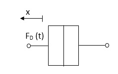
Fig 1. Damping force
Spring force: A spring stores potential energy. The releasing force of a string is proportional to the displacement.
Fk(t)  x(t)
x(t)
Fk(t) = k x (t)
Fk(t) = k 
K = string constant N/m.
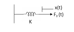
Fig 2. Spring force
Rotational mechanical system:
The motion of a body about a fixed axis is called as Rotational motion. The types of torques which can resist the motion are
Inertial Torque: - The inertial torque is the product of moment of inertia I and angular acceleration.
TI(t) = J (t)
(t)
TI(t) = Jd/dt w(t)
TI(t) = Jd2ø(t)/dt2(N-m)
W (t) – Angular velocity
Ø(t) = Angular displacement
Damping Torque: - it is product of damping efficient B and angular velocity w
T0 (t) = B w(t)
T0(t) = B d/dt ø(t)
Spring Torque: - It is the product of torsional stiffness and angular displacement
Tø(t) = k ø(t)
K = N.m/rad

Fig 3. Spring Torque
D’Alembert’s Principle
For anybody, the algebraic sum of externally applied forces and the forces resisting motion in any given direction is zero.
Ex.
In above figure applying D’Alemberts principle to write the equation of motion
As force f(t) acts downwards all other forces (of k,B,x) acts Opposite to it to considering f(t) as the and all other forces negative.
F(t)+fm (t) + fD(t) +fx(t) =0
f(t)- M d2x(t)/dt2+B dx(t)/dt +x(t)
Example
Draw the free body diagram and write the differential equation for system below.
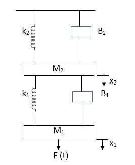
Fig 4. Mechanical system
Soln: The free body diagram for M1 will be
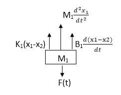
Fig 5. FBD
F(t) = M1 d2/dt2x1+ B1 d/dt (x1-x2)+ k1(x1-x2)
Similarly for M2we have
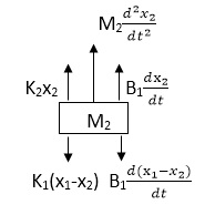
Fig 6. FBD
K1(x1-x2) + B1d/dt(x1-x2) = k2x2+M2d2/dt2+B2dx2/dt
Key takeaway
Analogy Between Electrical and Mechanical System:
Force -voltage | Force -current | Mechanical Translatory | Mechanical Rotational |
1.Voltage (v) | Current | Force (f) | Torque (T) |
2.Charge(q) | Flux (ø) | Displacement(x) | Angular Displacement(ø) |
3.current. | Voltage | Velocity v(t) | Angular velocity(w) |
4.Inductance(l) | Capacitance(c) | Mass (m) | Moment of inertia (J) |
5. Resistance(R) | Conductance G= (1/R) | Damping coefficient (B) | Damping Coefficient (B) |
6.Reciprocal of capacitance(1/c) | Inverse of Inductance (1/L) | Stiffness (K) | Stiffness(K) |
It is the ratio of Laplace transform of the output to Laplace transform of input with all initial conditions zero.

Fig 7. System with Transfer Function G(s)
Poles and zero of a Transfer Function:
The transfer function can be represented by the ratio of two polynomials
G (S) = a0sn+a1 sn-1-------+an/b0sm+b1sm-1+-----+bn
a0—an ---- constants
G(S) = K(s+z1) (s+z2) (as2+bs+c)/(S+A) (s+p2) (As2+Bs +c)
K= a0/b0 ( Gain of system)
For poles –They are the values of s for which
G(S)
(S+p1)(S+p2)(AS2 + BS + C) = 0
S= p1, -p2 , -B±B2-4Ac/2A
For ZEROS – They are the values of s for which
G(S) 0
S=-z1, -z2 , -b±b2-4ac/2a
- Location of poles and zeros in s place determines the reliability of the system
- There can be multiple poles and zeros
- The numerator of transfer function when equalized to zero gives zero of system
- The denominator of transfer function which equalized to zero gives poles of system.
Key takeaways
- The numerator of transfer function when equalized to zero gives zero of system.
- The denominator of transfer function which equalized to zero gives poles of system.
Advantages of Block diagram reduction technique:
- Very simple to Construct the Block diagram of complicated electrical & mechanical systems.
- The function of individual element can be visualized form block diagram
- Individual as well as overall performance of the system can be studied by the if shown in Block diag.
- Overall CLTf can be easily calculated by Block diag reduction rules.
Disadvantages of Block diagram reduction technique:
It does not include any information above physical construct of system (completely mathematical approach).
a) Source of energy in generally not shown in the block diag so w.g diff. Block diag can be drawn for the same function
CLTf: -ve feedback
C(s)/R(s)= G(s)/1+G(s)H(s)
CLTF: +ve feedback
C(S)/R(S) = G(S)/1-G(s)H(S)
Rules of Block diagram Algebra:
Block in cascade

Moving summing point after a block

Moving summing point ahead of block

Moving take off point after a block

Moving take off point ahead a block

Eliminating a feedback Loop

Fig 8. Block Diagram Reduction Techniques
Q. Reduce given B.D to canonical (simple form) and hence obtain the equivalent Tf = c(s)/ R(S)?
Sol: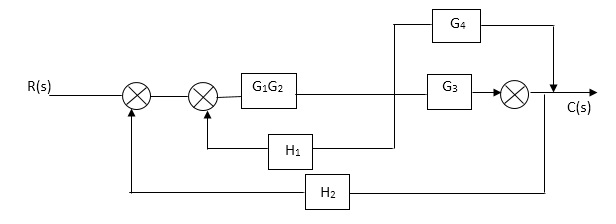


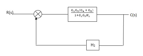
Fig 9. Final reduced block diagram
C(S)/R(S) = (G1G2) (G3+G4)/1+G1G2H1)/1-G1,G2(G3+G4) H2/1+G1G2H1
= G1G2(G3+G4)/1+G1G2H1-G1G2H2(G3+G4)
=G1G2(G3+G4)/1+(H1-H2)(G1G2) (G3+G4)
C(s)/R(S) = G1G2(G3+G4)/1+(H1-H2(G3+G4)) G1 G2
Q) Reduce the Block diagram
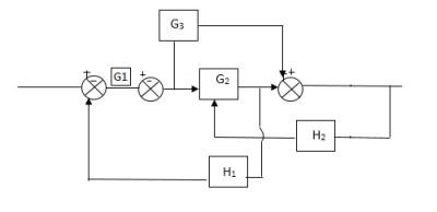
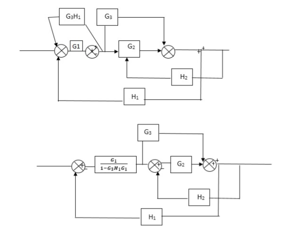
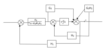
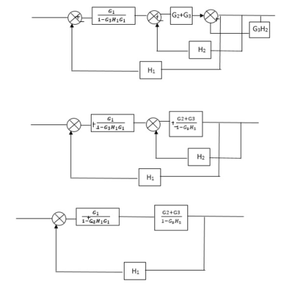
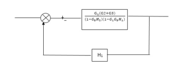
Fig 10. Final Reduced Block diagram
C(s)/R(s)= G1(G3+G2)/(1-G1G3X1) (1-G2X2) H1
= G(G3+G2)/(1-G3G1H1) (1-G2H2) + G1H1(G3+G2)
= G1(G3+G2)/1-63G1H1-G2H2+G1H1(G3+G2H1
=G1(G3+G2)/1-G3H2+G1G2H1(1+G3H2)
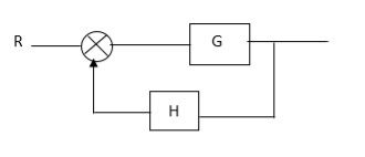
Fig 11. Block Diagram

Fig 12. SFG
Q:
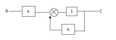
Ra+cb =c
c/R= a/1-b
RULES:
1) The signal travels along a branch in the direction of an arrow.
2) The lip signal is multiplied by the transmittance to obtain the o/p.
3) I/p signal at a node is sum of all the signals entering at that node.
4) A node transmits signal at all branches leaving that node.
Q. The SFG shown has forward path and singles isolated loop determine overall transmittance relating X3 and X1?
Sol:
X1- I/p node
X2-Intenmediale node
X3- o/p node
Ab- forward path (p)
Bc- 1 loop (L)
At node XQ:
X2 = x1a + x3c [Add i/p signals at node]
At node x3:
x2b =x3
(x1a+x3c) b = x3
X1ab = x3 (1-bc)
X1 = x3 (1-bc)/ab
Ab/(1-bc) = x3/x1
T= p/1-L

X1:- I/p node x2, x3,x4,x5,Qnlexmedili node
X0:- o/p node abdeg:- forward path
Bc, ef :- Loop [isolated]
x2 = ax1+c x3
x3= bx2
x4 = d x3+f x5
x5 = e x4
x6= g x5
x6 = g(e x4) = ge [dx3+ e f x5]
xb = ge [d (bx2) + f (e x4)]
xb = ge [ db (ax1+cx3) + fe (dx3+ fx5)]
xb = ge [db (ax1+cb (ax1+x3) +fe[cdbx2]+
f( e [db (ax1+ cx3)
x2 = ax1 + cb (x2) x4 = d bx2 + f exq
x2 = ax1 + cbx2 = db (d4) + fe/1-cb
x2 = ax1/(1-cb) xy = db x2 + f x6/g
xy = db [ax1]/1-cb + f xb/g
x5 = c db( ax1)/1-cb + efxb/g
xb = gx5
= gedb (ax1)/1-cb + g efxb/g
Xb = gx5
Gedb (ax1)/1-cb + g efxb/g
(1- gef/g) xb = gedb ax1/1-ab
Xb/x1 = gedb a/ (1- ef – bc + beef
Xb/x1 = p/ 1- (L1+L2) + L1 L2 for isolated loops
The feedback systems are having many advantages over the non-feedback system as we have seen earlier. So, some performance parameters can be controlled through this feedback system such as sensitivity, noise etc. Sensitivity is a parameter which forecasts the effectiveness of feedback in reducing the influence of these variations on system performance. [Reference 4]
The output of the open loop system is given by
C(s) = G(s)R(s)
Now due to variation in parameters G(s) changes to [G(s)+G(s)]. The output will now become
C(s)+ C(s) = [G(s)+ G(s)] R(s)
C(s) = G(s)R(s)
For closed loop system the output is given as

Now due to variation in parameters it becomes

The above equation shows that if there is variation in parameters then G(s) is reduced by factor of 1+G(s)H(s). The variation in overall transfer function T(s) due to change in G(s) is defined as sensitivity.

When there is small change in G(s) then sensitivity becomes

 : Sensitivity of T w.r.t G
For closed loop system the sensitivity will be

For open loop system

As T=G
The sensitivity of T w.r.t H is given as

The above equation shows that for large values of GH sensitivity of the feedback system w.r.t H approaches to unity.
Key takeaway
For closed loop system the sensitivity w.r.t G is reduced by a factor of (1+GH) as compared to the open loop system.
The feedback helps to control the disturbances as they generate an error signal. The signal flow graph for closed loop system is given by
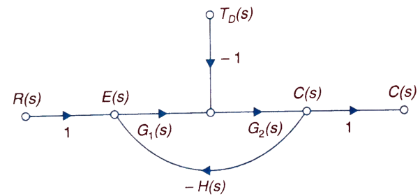
Fig 13. Closed loop system with disturbance signal
 =
= 
Where:
TD(s) = Disturbance signal.
For |G1G2H(s)|>>1 over the range of s
 =
=
The signal flow graph of a system with noise signal N(s) in the feedback path. The gain is given by
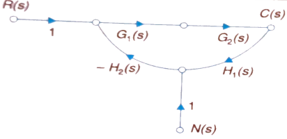
Fig 14. SFG for noise feedback function
 =
= 
For  >>1
>>1
Cn(s) = 
The feedback reduces sensitivity, improves transient response and minimises the effects of disturbance signal in control system.
Servomechanism is also called servo which is a device usually error sensing device connected as a feedback element to correct the action of a mechanism. Here instead of controlling a device by variable input signal, the device is controlled by feedback signal.
The input signal applied to such systems generate the required output which is compared again to the input signal. If the device achieves its desired output, there will be no longer the logical difference between the two signals. Hence, the primary task of servomechanism is to maintain the output of a system at the desired value in the presence of disturbances.
Servomotors: These motors are used in feedback control system. These are also known as control motors. These motors should have low rotor inertia and high speed of response. The servomotors used in the feedback control systems should have linear control signal and rotor speed.
Types of Servomotors:
(a). A.C. Servomotors
(b). D.C. Servomotors
(a). A.C. Servomotors:
A.C servomotor is a two-phase ac induction motor. There are two windings in this motor, one is fixed or reference winding is supplied with a fixed voltage and frequency from a constant voltage source. Second winding is control winding with variable supply voltage of same frequency as reference winding but having a phase displacement of 900 electrical. A flux is induced due to the phase change which cuts the conducting bars of rotor and causes a time varying current, this current produces a time varying flux and reacts with the stator flux causing the rotor to rotate.
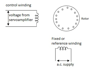
The rotor of A.C. Servomotors are of two types:
(a). Squirrel Cage Rotor
(b). Drag cup type rotor
(a). Squirrel cage rotor: They have high resistance as the rotor is having large length and small diameter. The air gap here is kept small.

(b). Drag cup type motor: For the drag cup rotor there are two air gaps. For the rotor a cup of non-magnetic conducting material is used. A stationary iron core is placed between the conducting cup to complete the magnetic circuit. The resistance of drag cup type is high and therefore, has high starting torque. Generally aluminium is used for cup.
Torque-speed characteristic:
The torque speed characteristics of the two phase servomotor depends on ratio of reactance to resistance(X/R).
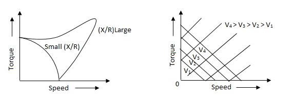
(i). For high ‘R’ and low X, the characteristic is linear and
(ii). For high X and low R, it becomes non-linear.
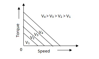
The torque-speed characteristic for various voltage is almost linear.
(b). D.C. Servomotor:
D.C. Servomotor are separately excited or permanent magnet dc servomotors. The armature of D.C. Servomotors is having large resistance and hence torque-speed characteristic is linear.
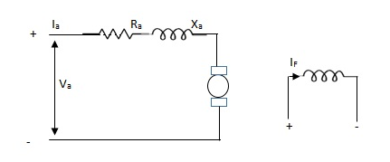
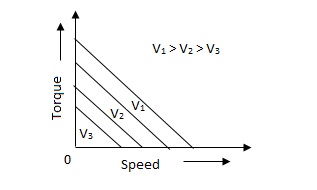
The above graph fig (b), clearly shows that the torque-speed characteristics is a function of control winding voltage as shown below.
T = mw + KVc -- (1)
Where T = Torque developed by motor
w = angular velocity
Vc = control winding voltage
Taking laplace of above equation (1),
T(S) = mS Q(S) + KVc - - (2)
T(S) = JS2Q(S) + FSQ(S) - - (3)
Above equation(3) is the dynamic equation with,
J – moment of inertia
F – coefficient of friction of motor
From equation (2) and (3) the block diagram will be,

Q(S)/Vc = K/Js + F + m - - (4)
Comparison between A.C. Servomotor & D.C. Servomotor
| A.C. Servomotor | D.C. Servomotor |
|
|
|
1. | They are less efficient | They are more efficient |
2. | They have low power output | They have high power output |
3. | No noise so has smooth operation | These motors have noisy operation |
4. | They do not have any radio frequency noise | These motors have brushes so produce radio frequency noise |
5. | They are maintenance free because of no brushes and slip rings | For these motors maintenance is required. |
Control system components
A closed loop control system consists of three basic elements: the feedback element, controller and controlled system. The controller consists of error detector and control elements.

The control element manipulates the actuating signal preferably to different power stage so as to fed to the controlled system. The power stage in control elements is essential for the control signal to drive controlled system. Control elements plays a vital role to get the desired output.
Electrical System
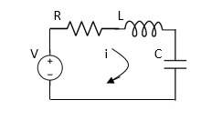
Applying Kirchoff’s voltage Law
V= Ri +Ldi/dt +1/c
V= Rdq/dt + L d2q/dt2+q/c
Now By kirchoff’s current low
I= V/R+ 1/L  + cdv/dt
But V= dø/dt
I= 1/R dø/dt + 1/L ø+cd2ø/dt2
But v= dø/dt
I= 1/R dø/dt+ 1/L. ø+c d2ø/dt2
Q.2 For the given mechanical system below draw the analogues system (force. Voltage) & find V0(s)/V1(s)
Soln. form the table above we can find the analogues values of system components.
(1) Consider two displacement as two nodes.
(2) If masses are present connect them to reference lines
(3) Connect other elements of system to the nodes
(4) Applying modal analysis to find the system equation.
Let Z1 = R2 11 1/c2
=R2*1/c2s/R2+1/c2s
Z1= R2/1+R2c2s
Let Z2 = R1+1/c1s
Z2= 1+R1c1s/c1s
V0(s)/vi(s) = z2/z1+z2
= 1+R1c1s/c1s/R2/1+R2c2s+1+R1c1s/c1s
V0(s)/v0(s) =(c1+R1c1s) (1+R2c2s)/R2c1s+1+sR1c1s2R1R2c1c2
Electromechanical
Armature Controlled dc motor:
In armature controlled motors the time constant is small and hence response is last The efficiency is better than field cannot. The transfer function is calculated below.

Fig 15. Armature controlled d.c servomotor
Applying kVL in armature circuit
V = Raia+ Ldia/dt +E-----(5)
Where
V= applied voltage
Ra = armature resistance
La = Armature inductance
Ia= Armature current
If= field current
E= Induced emf in armature
T= Torque developed by motor
But E= Kb w
E= kbdø/dt --------(6)
W =angular velocity
Kb= back emf
T= k ia-----(7)
The equation for torque will be
T= Jd2ø/dt2+Bdø/dt --------(8)
Taking Laplace of equation (5), (6), (7), (8)
V(S) – E(S) = I1(s) (Ra+sLa)
E(s) = kb s (s)
T(s) = k Ia (s)
T(S)= (s2J+SB) (S)
T(S) = (SJ+B) s (S)
(S)/v(s) k/(Ra+sla) (Js +B) s+ kkbs ------(a)
The Block diagram representation for above equation (a) is shown below.
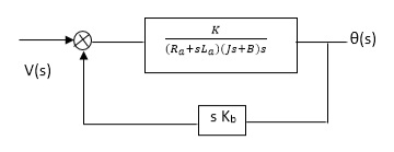
Fig. 16. Block diagram for armature-controlled D.C. Motor
Field controlled D.C. Servomotor:
For field controlled D.C. Motor the ratio L/R is large which means time controller for field circuit is large
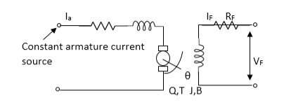
Fig. 17. Circuit for field controlled D.C motor
Applying KVL in field circuit
Vf= Rf If +Lfd If/dt------(10)
T = k øIa
ø If
ø= kfIf
:. T= kkfIa If
Let k, = KIa
T= k’Kf If --------(11)
Dynamic equation for torque is
T= Jd2/dt2 +Bd/dt ------- (12)
Taking Laplace of above equations
Vf(s) = Rf If (c)+SLf If(s) [Rf+SLf]
If= Vf(S)/Rf+ SLf--------(13)
T(s) = (S) [s2J+SB] --------(14)
T(S) = kkfVf(s)/Rf+SLf------ (15)
From equation (14) and (15) we get
(s)/ vf(s) = kkf/s (sJ+B) (Rf+sLf)
The block diagram representation of above equation (16) is shown in figure below

Fig 18. Block diagram for field controlled D.C. Servomotor
References:
1. Automatic Control system (II Edition) – Benjamin C, Kuo, PHI
2. Modern Control System, Drof, Bishop, Wesly Publication
3. Control system Engineering, S.K. Bhattacharya, Pearson Education.