Unit - 2
Source & Waveform Coding Methods
Source encoding is a process in which the output of an information source is converted into a r-ary sequence where r is the number of different symbols used in this transformation process. The functional block that performs this task in a communication system is called source encoder.
The input to the encoder is the symbol sequence emitted by the information source and the output of the encoder is r-ary sequence.
If r=2 then it is called the binary sequence
r=3 then it is called ternary sequence
r=4 then it is called quarternary sequence.
Let the source alphabet S consist of “q” number of source symbols given by S = {S1,S2…….Sq} . Let another alphabet X called the code alphabet consists of “r” number of coding symbols given by
X = {X1,X2………………………Xr}
The term coding can now be defined as the transformation of the source symbols into some sequence of symbols from code alphabet X.
Shannon’s encoding algorithm
The following steps indicate the Shannon’s procedure for generating binary codes.
Step 1:
List the source symbols in the order of non-increasing probabilities
S = {S1,S2,S3……………………Sq} with P = {P1,P2,P3…………………..Pq}
P1 ≥P2 ≥P3 ≥………………….Pq
Step 2
Compute the sequences
α 1 = 0
α 2 = P1 = P1 + α 1
α 3 = P2 + P1 = P2 + α 2
α 4 = P3 + P2 + P1 = P3 + α 3
...................
α q + 1 = Pq + Pq-1 + ..........+ P2 + P1 = Pq + α q
Step 3:
Determine the smallest integer value of “li using the inequality
2li ≥ 1/Pi for all i = 1, 2 .....................q
Step 4:
Expand the decimal number αi in binary form upto li places neglecting expansion beyond li places.
Step 5:
Remove the binary point to get the desired code.
Example:
Apply Shannon’s encoding (binary algorithm) to the following set of messages and obtain code efficiency and redundancy.
m 1 | m 2 | m 3 | m 4 | m 5 |
1/8 | 1/16 | 3/16 | ¼ | 3/8 |
Step 1:
The symbols are arranged according to non-increasing probabilities as below:
m 5 | m 4 | m 3 | m 2 | m 1 |
3/8 | ¼ | 3/16 | 1/16 | 1/8 |
P 1 | P 2 | P 3 | P 4 | P 5 |
The following sequences of α are computed
α 1 = 0
α 2 = P1 + α 1 = 3/8 + 0 = 0.375
α 3 = P2 + α 2 = ¼ + 0.375 = 0.625
α 4 = P3 + α 3 = 3/16 + 0.625 = 0.8125
α 5 = P4 + α 4 = 1/16 + 0.8125 = 0.9375
α 6 = P5 + α 5 = 1/8 + 0.9375 = 1
Step 3:
The smallest integer value of li is found by using
2 li ≥ 1/Pi
For i=1
2 l1 ≥ 1/P1
2 l1 ≥ 1/3/8 = 8/3 = 2.66
The smallest value ofl1 which satisfies the above inequality is 2 therefore l1 = 2.
For i=2 2l2 ≥ 1/P2 Therefore 2 l2 ≥ 1/P2
2 l2 ≥ 4 therefore l2 = 2
For i =3 2 l3 ≥ 1/P3 Therefore 2 l3 ≥ 1/P3 2 l3 ≥ 1/ 3/16 = 16/3 l3 =3
For i=4 2l4 ≥ 1/P4 Therefore 2 l4 ≥ 1/P4
2 l4 ≥ 8 Therefore l4 = 3
For i=5
2 l5 ≥ 1/P5 Therefore
2 l5 ≥ 16 Therefore l5=4
Step 4
The decimal numbers ai are expanded in binary form upto li places as given below.
α 1 = 0
α 2 = 0.375
0.375 x2 = 0.750 with carry 0
0.75 x 2 = 0.50 with carry 1
0.50 x 2 = 0.0 with carry 1
Therefore
(0.375) 10 = (0.11)2
α 3 = 0.625
0.625 X 2 = 0.25 with carry 1
0.25 X 2 = 0.5 with carry 0
0.5 x 2 = 0.0 with carry 1
(0.625) 10 = (0.101)2
α 4 = 0.8125
0.8125 x 2 = 0.625 with carry 1
0.625 x 2 = 0.25 with carry 1
0.25 x 2 = 0. 5 with carry 0
0.5 x 2 = 0.0 with carry 1
(0.8125) 10 = (0.1101)2
α 5 = 0.9375
0.9375 x 2 = 0.875 with carry 1
0.875 x 2 = 0.75 with carry 1
0.75 x 2 = 0.5 with carry 1
0.5 x 2 = 0.0 with carry 1
(0.9375) 10 = (0.1111)2
α 6= 1
Step 5:
α 1 = 0 and l1 = 2 code for S1 ----00
α 2 =(0.011) 2 and l2 =2 code for S2 ---- 01
α 3 = (.101)2 and l3 =3 code for S3 ------- 101
α 4 = (.1101)2 and l4 =3 code for S ----- 110
α 5 = (0.1111)2 and l5 = 4 code for s5 --- 1111
The average length is computed by using
L = 
= 3/8 x 2 + ¼ x 2 + 3/16 x 3 + 1/8 x 3 + 1/16 x 4
L= 2.4375 bits/msg symbol
The entropy is given by
H(s) = 3/8 log (8/3) + ¼ log 4 + 3/16 log 16/3 + 1/8 log 8 + 1/16 log 16
H(s) =2.1085 bits/msg symbol.
Code efficiency is given by
ηc = H(s)/L = 2.1085/2.4375 = 0.865
Percentage code effeciency = 86.5%
Code redundancy
R ηc = 1 - ηc = 0.135 or 13.5%.
First the source symbols are listed in the non-increasing order of probabilities
Consider the equation
q = r + (r-1 )α
Where q = number of source symbols
r = no of different symbols used in the code alphabet
The quantity α is calculated and it should be an integer . If it is not then dummy symbols with zero probabilities are added to q to make the quantity) α an integer. To explain this procedure consider some examples.
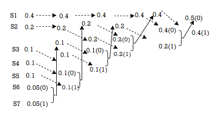
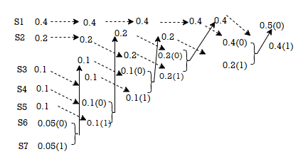
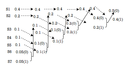
Given the messages X1,X2,X3,X4,X5 and X6 with respective probabilities of 0.4,0.2,0.2,0.1,0.07 and 0.03. Construct a binary code by applying Huffman encoding procedure. Determine the efficiency and redundancy of the code formed.
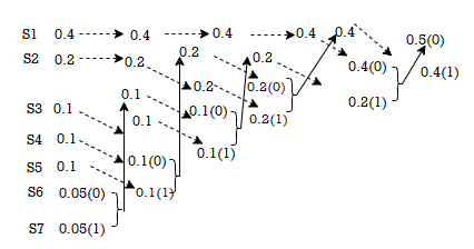
Now Huffmann code is listed below:
Source Symbols | Pi | Code | Length (li) |
X1 | 0.4 | 1 | 1 |
X2 | 0.2 | 01 | 2 |
X3 | 0.2 | 000 | 3 |
X4 | 0.1 | 0010 | 4 |
X5 | 0.07 | 00110 | 5 |
X6 | 0.03 | 00111 | 5 |
Now Average length (L) = 
L = 0.4 x 1 + 0.2 x 2 + 0.2 x 3 + 0.1 x 4 + 0.07x 5 + 0.03 x 5
L = 2.3 bits/msg symbol.
Entropy H(s) = =  log 1/Pi
0.4 log 1/0.4 + 0.2 log 1/0.2 + 0.1 log 1/0.1 + 0.07 log 1/0.07 + 0.03 log 1/0.03
H(s) = 2.209 bits /msg symbol.
Code effeciency = nc = H(s) /L = 2.209/2.3 = 96.04%.
Rate Distortion Basics
When it comes to rate distortion about random variables, there are four important equations to keep in mind.
1. The entropy | H(X) =  |
2. Conditional entropy | H(X|Y) =  |
3. Joint entropy | H(X, Y) =  |
4. Mutual Information | I(X; Y) = H(X) – H(X | Y) |
H(X, Y) = H(X) + H(Y | X)
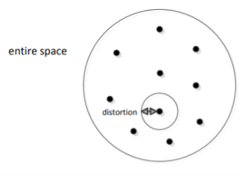
For a binary file which is of our interest, we use Hamming Distance (probability of error distortion) for distortion function. Another important case is Quantization. Suppose we are given a Gaussian random variable, we quantize it and represent it by bits. Thus we lose some information. What is the best Quantization level that we can achieve? Here is what we do. Define a random variable X ∈ x. Our source produces a n length vector and we denote it by Xn = X1, X2, ......, Xn, where the vector is i.i.d. And produced according to the distribution of random variable X and p(x) = P r(X = x). What we do is to encode the file. After the encoder, the function fn gives us a compressed string. Then we map the point in the space to the nearest codeword and we obtain an index which is represented by log Mn bits. Finally, we use a decoder to map the index back which gives us one of the codeword ˆx in the space.

Above is a figure of rate distortion encoder and decoder. Where fn = Xn ! {1, 2, .......Mn} is the encoder, and Xˆ n is the actual code we choose.
The distortion between sequences xn and xˆn is defined by

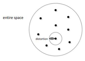
There are Mn points in the entire space, each point is a chosen codeword (center). We map each data point to the nearest centre
Thus, we know that the distortion of a sequence is the average distortion of the symbol-to-symbol distortion. We would like d(xn, xˆn) D. The compression rate we could achieve is

The Rate distortion function R(D) is the minimization of log Mn/n such that

Theorem(Fundamental theory of source coding): The information rate distortion function R(D) for a source X with distortion measure d(x, xˆ) is defined as

From the above equation, we could see that no n involved. This is called a single letter characterization. For the subscript of the summation, we know that

First of all, let’s see what is Chain Rule. It is defined as below: H(X1, X2, X3, ......, Xn) = H(X1) + H(X2|X1) + H(X3|X1, X2) + ...... + H(Xn|X1, X2, ......, Xn1) Chain rule can be easily proved by induction.
Two Properties of R(D)
We now show two properties of R(D) that are useful in proving the converse to the rate-distortion theorem.
1. R(D) is a decreasing function of D.
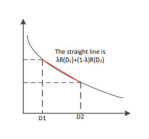
2. R(D) is a convex function in D.
For the first property, we can prove its correctness intuitively: If R(D) is an increasing function, this means that the more the distortion, the worse the compression. This is definitely what we don’t want. Now, let’s prove that second property.


Therefore, R(D) is a convex function of D.
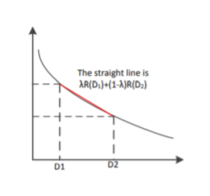
For the above proof, we need to make the argument that distortion D is a linear function of p(ˆx|x). We know that the D is the expected distortion and it is given as D = Pp(x, xˆ)d(ˆx, x) = Pp(x)p(ˆx|x)d(x, xˆ). If we treat p(ˆx|x) as a variable and both p(x) and d(x, xˆ) as known quantities, we know that D is a linear function of p(ˆx|x). Therefore, R(D) is a convex function of p(ˆx|x). The proof that I(X; Xˆ) is a convex function of p(ˆx|x) will not be shown here.
Scalar Quantization
Let us begin by considering the case of a real-valued (scalar) memoryless source. Such a source is modeled as a real-valued random variable, thus fully characterized by a probability density function (pdf) fX. Recall that a pdf fX satisfies the following properties: fX(x) ≥ 0, for any x ∈ R,


Where P[X ∈ [a, b]] denotes the probability that the random variable X takes values in the interval [a, b]. To avoid technical issues, in this text we only consider continuous pdfs.
Consider the objective of transmitting a sample x of the source X over a binary channel that can only carry R bits, each time it is used. That is, we can only use R bits to encode each sample of X. Naturally, this restriction implies that we are forced to encoding any outcome of X into one of N = 2R different symbols (binary words). Of course, this can be easily generalized for D-ary channels (instead of binary), for which the number of different words is DR; however, to keep the notation simple, and without loss of generality, we will only consider the case of binary channels. Having received one of the N = 2R possible words, the receiver/decoder has to do its best to recover/approximate the original sample x, and it does so by outputting one of a set of N values. The procedure described in the previous paragraph can be formalized as follows. The encoder is a function E : R → I, where I = {0, 1, ..., N − 1} is the set of possible binary words that can be sent through the channel to represent the original sample x. Since the set I is much smaller than R, this function is non-injective and there are many different values of the argument that produce the same value of the function; each of this sets is called a quantization region, and is defined as
Ri = {x ∈R : E(x) = i}.
Since E is a function defined over all R, this definition implies that the collection of quantization regions (also called cells) R = {R0, ..., RN−1} defines a partition of R, that is,
(i 6= j) ⇒ Ri ∩Rj = ∅
The decoder is a real-valued function D : I → R; notice that since the argument of D only takes N different values, and D is a deterministic function, it can also only take N different values, thus its range is a finite set C = {y0, ..., yN−1} ⊂ R. The set C is usually called the codebook. The i-th element of the codebook, yi , is sometimes called the representative of the region/cell Ri . Considering that there are no errors in the channel, the sample x is reproduced by the decoder as D (E(x)), that is, the result of first encoding and then decoding x. The composition of the functions E and D defines the so-called quantization function Q : R → C, where Q(x) = D (E(x)). The quantization function has the following obvious property
(x ∈ Ri) ⇔ Q(x) = yi ,
Which justifies the term quantization. In other other, any x belonging to region Ri is represented at the output of the system by the corresponding yi . A quantizer (equivalently a pair encoder/decoder) is completely defined by the set of regions R = {R0, ..., RN } and the corresponding representatives C = {y0, ..., yN−1} ⊂ R. If all the cells are intervals (for example, Ri = [ai , bi [ or Ri = [ai , ∞[) that contain the corresponding representative, that is, such that yi∈ Ri , the quantizer is called regular. A regular quantizer in which all the regions have the same length (except two of them, which may be unbounded on the left and the right) is called a uniform quantizer. For example, the following set of regions
And codebook define a 2-bit (R = 2, thus N = 4) regular (but not uniform) quantizer:
R = {] − ∞, −0.3], ]− 0.3, 1.5], ]1.5, 4[, [4, ∞[} and
C = {−1, 0, 2, 5}.
As another example, the following set of regions/cells and codebook define a 3-bit (R = 3, thus N = 8) uniform quantizer:
R = {] − ∞, 0.3], ]0.3, 1.3], ]1.3, 2.3], ]2.3, 3.3], ]3.3, 4.3], ]4.3, 5.3], ]5.3, 6.3], ]6.3, ∞[}
C = {0, 1, 2, 3, 4, 5, 6, 7}.
Vector Quantization
In vector quantization the input to the encoder, that is, the output of the source to be quantized, is not a scalar quantity but a vector in Rn. Formally, the source is modeled as a vector random variable X ∈ R n , characterized by a pdf fX(x). Any pdf defined on R n has to satisfy the following properties: fX(x) ≥ 0, for any x ∈ Rn,


Where P[X ∈ R] denotes the probability that the random variable X takes values in
Some set R ⊆ R n . To avoid technical issues, we consider only continuous pdfs. In the vector case, the encoder is a function E : R n → I, where I = {0, 1, ..., N − 1}. As in the scalar case, this function is non-injective and there are many different values of the argument that produce the same value of the function; each of this sets is called a quantization region (or cell), and is defined as
Ri = { x ∈  : ε(x) = i}
Since E is a function defined over all R n , this definition implies that the collection of quantization regions/cells R = {R0, ..., RN−1} defines a partition of R n , that is
( i ≠ j) Rj ∩ Rj = ∅ and 
The decoder is a function D : I → R n ; as in the scalar case, since the argument of D only takes N different values, and D is a deterministic function, it can also only take N different values, thus its range is a finite set C = {y0, ..., yN−1} ⊂ R n . The set C is still called the codebook. The i-th element of the codebook, yi , is the representative of the region/cell Ri . Considering that there are no errors in the channel, the sample x is reproduced by the decoder as D (E(x)), that is, the result of first encoding and then decoding x. The composition of the functions E and D defines the so-called vector quantization function Q : R n → C, where Q(x) = D (E(x)). As in the scalar case, the quantization function has the following obvious property
(x ∈ Ri) ⇔ Q(x) = yi
Similarly to the scalar case, a vector quantizer (VQ) (equivalently a pair encoder/decoder) is completely defined by the set of regions R = {R0, ..., RN } and the corresponding codebook C = {y0, ...yN−1} ⊂ R n . A VQ in which all the cells are convex and contain its representative is called a regular VQ. Recall that a set S is said to be convex if it satisfies the condition
x, y ∈ S ⇒λx + (1 −λ)y∈ S, for any λ∈ [0, 1];
In words, a set is convex when the line segment joining any two of its points also belongs to the set. Observe that this definition covers the scalar case, since the only type of convex sets in R are intervals (regardless of being open or close).
There are essentially two approaches to speech coding: waveform coding and vocoding. ADPCM falls into the category of waveform coding, which attempts to preserve the waveform of the original speech signal. Speech coders based on CELP are vocoders, a technique that attempts to model the generation of speech. The quality of waveform coders can be compared by direct comparison between the decoded waveform and the original waveform. Since vocoders do not attempt to preserve the waveform, this approach for quality comparison is not applicable. For this reason, the quality of most speech coding techniques is compared by a measure of user perception. The mean opinion score, MOS, is a number between 0 and 5 which represents the average quality as judged by listeners, 0 being the worst. A score of 4 is labeled ‘toll quality’ and is the quality of signal perceived by users in a typical long-distance call. Two other characteristics often used to compare coding schemes are complexity and delay. Complexity, commonly measured in MIPS often relates to system implementation requirements. Delay is the time required for an input signal to be coded and reconstructed at the receiver and is important due to its impact on conversation quality.
ADPCM, adaptive differential pulse code modulation, is one of the most widely used speech compression techniques used today due to its high speech quality, low delay, and moderate complexity. ADPCM is a waveform coder, and achieves its compression improvements by taking advantage of the high correlation exhibited by successive speech samples. Referring to Figure below, the ADPCM encoder first calculates the difference between the input signal, typically A-law or u-law, and a signal generated by a linear adaptive predictor. Due to the high correlation between samples, the difference signal has a much lower dynamic range than the input signal. The reduced dynamic range means fewer bits are required to accurately represent the difference signal as compared to the input. Transmitting only the quantized difference signal reduces the transmitted data rate. A four-bit quantization translates to a 32 kbps data rate for a compression ratio of 2:1. Higher quality is achieved through the adaptive nature of the quantization.
Analyzing the time varying characteristics of the difference signal, the size of the quantization steps, and the rate at which quantization steps change facilitate higher accuracy for a wider dynamic range. As mentioned, signal received at the decoder is the quantized difference signal. The ADPCM decoder is essentially the reverse process of the encoder. More than one standard exists for ADPCM. The International Telegraph and Telephone Consultative Committee, CCITT first adopted recommendation G.721 that defines standard ADPCM operating at 32 kbps using 4 bit quantization. This standard was eventually encompassed by recommendation G.726, which expanded the original definition to include data rates of 40, 32, 24, and 16 kbps. This relates to 5, 4, 3, and 2-bit quantization of the difference signal. A third recommendation was also adopted, G.727, addressing 5, 4, 3, and 2-bit sample embedded ADPCM which is effectively a variable rate definition of G.726.
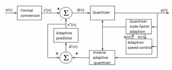
Fig. ADPCM Encoder
As most cellular applications demand a speech coder that can operate at under 8 kbps, even at 2-bit quantization ADPCM is considered to have high bandwidth demands. The relatively low complexity of ADPCM makes it attractive for systems, which require waveform preservation or have relaxed bandwidth restrictions. The latter of these fit cordless telephony and microcell applications well. The G.721 ADPCM has been specified in a few popular cordless standards. Great Britain introduced the CT2 system to address second generation cordless applications. The DECT, Digital European Cordless Telephony, system also covers second generation cordless, facilitating compatible systems across Europe. The third generation Personal Access Communication System, PACS, also specifies voice coding using 32 kbps ADPCM.
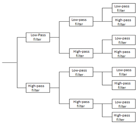
A source output is decomposed into its constituents. In each constituent is in afforded and decoded separately to improve compression performance. It separates the source output into bands of different frequency using digital filters. Different filters are used like low pass filter, high Pass filter.
A system that blocks certain frequency components is called a filter. Filters that only pass components below certain frequency f0 are Low Pass filters. Filters that block all components by low frequency f0 are called High Pass filter. Filters that pass components that have frequency content above certain frequency f1 and below frequency f2 are called band pass filters.
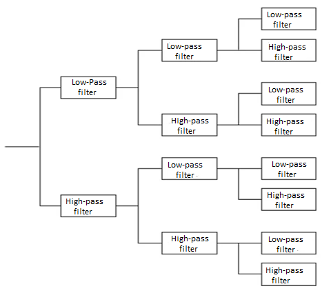
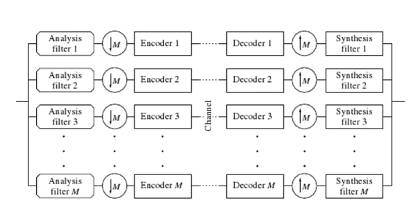
It consists of 3 phases
1) Analysis
2) Quantization and coding
3) Synthesis
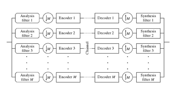
Source output is pass through entire, non overlapping or overlapping filters. The range of frequency at the foot is less than the range of frequency at the input to the filter. The process of reducing the number of samples is called decimation or down sampling. The amount of decimation depends on the ratio of bandwidth of the filter output. To filter input. The bandwidth of the filter output is 1/M the bandwidth of filter input. Then the decimation will be of M.
Quantization and Coding
Allocation of beats between the submits is the main issue. Bits are located according to the measure of information content between sub and. When the information content of bands is very different, bit allocation procedure has a significant impact.
Synthesis
Quantised and coded coefficients are used for the construction of the original signal. From its urban common code. Examples for decoded at the receiver. Decoded values Aaron sampled by inserting an appropriate number of zeros between samples. The UNSAMPLED signals are pass through Bank of Reconstruction filter when the number of samples for second has been brought back to the original red. Summation of the reconstruction filter gives the final reconstructed output.
In order to maintain acceptable quality below the 8 kbps data rate, a fundamentally different approach to speech coding and sizeable jump in complexity is encountered. The most widely documented scheme for speech coding operating at under 8 kbps is CELP, code excited linear prediction. CELP actually represents a class of vocoders, all computationally expensive, which are based on the analysis and synthesis of incoming speech. The scope of this project limits the focus on one variation of CELP, and for the purpose of example and demonstration, this project focuses on the U.S. Federal Standard 1016 that defines a CELP algorithm operating at 4.8 kbps.
Opposed to waveform encoding, the goal of CELP algorithms is to code and transmit the minimal amount of information necessary to synthesize speech which is audibly perceived to be accurate. This is achieved by modeling aspects of the speech generation process, effectively modeling the vocal tract. Two components are generally found in these models, one which models the long term speech structure, the pitch, and another, which models the short-term speech structure, the formant. Relying on human perception as the measure of quality makes measurements of SNR irrelevant, and the overall rating of a specific implementation is in terms of mean opinion score, or MOS.
The technique of incorporating synthesis as a fundamental part of signal analysis is common to CELP algorithms and is why they are often referred to as analysis-by-synthesis techniques. Another departure from ADPCM, CELP algorithms work on frames of sampled input speech. The length and duration of the frame depends on the specific CELP algorithm. USFS-1016 operates on 30 ms frames which are furthure split into four 7.5 ms subframes.
Termed vector quantization, the frames of sampled input speech, input vectors, are compared to an existing set of excitation vectors called the code book. The search for the code book entry which produces the closest match is often an exhaustive search, making this class of algorithms computationally expensive. Each code book entry is applied to an LPC filter to generate a synthesized speech vector.
The synthesized sample is compared to with the input vector and rated with a perceptual weighing filter. The index of the code book with the vector producing the closest perceptual match to the input vector is selected and transmitted. Low bit rates are achieved because only the code book indices, LPC filter coefficients, and gain information are transmitted. Figure below, adapted, shows the block diagram for the USFS-1016 CELP encoder. Two code books and a 10th order LPC filter are used in USFS-1016. The 256 entry adaptive code book models the long-term speech structure, and the 10th order LPC filter models the short term speech structure. The residual signal remaining after adaptive code book quantization and LPC synthesis is modeled by the static 512 entry stochastic code.
The encoder transmits the index and gain for both stochastic and adaptive code books each subframe, or four times per 30 ms frame. The LPC filter coefficients are transmitted only once per frame. Modeling the long-term speech by the 256 entry adaptive code book improves quality at the cost of additional computational load of the same complexity as the 512 entry stochastic code book look-up. At the expense of quality, bit rates below 4.8 kbps can be achieved by limiting the search of the stochastic code book. Disadvantages associated with USFS-1016 CELP include the less than toll quality speech (3.2 MOS), and high processing delays (90 ms).
The frame-by-frame analysis, coupled with the high processing demands introduces delay which can degrade quality of conversation and introduce difficulties in related speech processing components, such as echo canceling. Other standards have been introduced which addressed both of these issues. Important standards often referenced in current literature include CCITT recommendation G.728 for LD-CELP, or low delay CELP, and G.729 for CS-ACELP, conjugate structure algebraic CELP. Both offer quality improvements but have higher bit rates (16 kbps and 8 kbps respectively). Less complex than LD-CELP, CS-ACELP operates at half the bit rate and offers toll quality speech. Yet another algorithm, VSELP, is defined in the IS-54 standard.
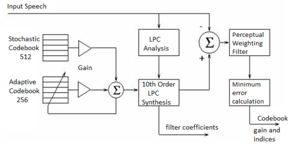
Fig. CELP Encoder
References:
1. Lathi B.P. - Modern Digital and Analog communications systems - PRISM Indian Ed.
2. Digital Communication: J.S.Chitode
3. Digital Communication (Fundamentals & applications): Bernard Scalr
4. Introduction to Error Control Codes: Salvatore Gravano
5. OFDM For wireless communication systems: Ramjee Prasad
6. Modern Communication systems (Principles and application): Leon W. Couch II (PHI)
7. Error Control Coding: Shu Lin & Daniel J.Costello
Unit - 2
Source & Waveform Coding Methods
Source encoding is a process in which the output of an information source is converted into a r-ary sequence where r is the number of different symbols used in this transformation process. The functional block that performs this task in a communication system is called source encoder.
The input to the encoder is the symbol sequence emitted by the information source and the output of the encoder is r-ary sequence.
If r=2 then it is called the binary sequence
r=3 then it is called ternary sequence
r=4 then it is called quarternary sequence.
Let the source alphabet S consist of “q” number of source symbols given by S = {S1,S2…….Sq} . Let another alphabet X called the code alphabet consists of “r” number of coding symbols given by
X = {X1,X2………………………Xr}
The term coding can now be defined as the transformation of the source symbols into some sequence of symbols from code alphabet X.
Shannon’s encoding algorithm
The following steps indicate the Shannon’s procedure for generating binary codes.
Step 1:
List the source symbols in the order of non-increasing probabilities
S = {S1,S2,S3……………………Sq} with P = {P1,P2,P3…………………..Pq}
P1 ≥P2 ≥P3 ≥………………….Pq
Step 2
Compute the sequences
α 1 = 0
α 2 = P1 = P1 + α 1
α 3 = P2 + P1 = P2 + α 2
α 4 = P3 + P2 + P1 = P3 + α 3
...................
α q + 1 = Pq + Pq-1 + ..........+ P2 + P1 = Pq + α q
Step 3:
Determine the smallest integer value of “li using the inequality
2li ≥ 1/Pi for all i = 1, 2 .....................q
Step 4:
Expand the decimal number αi in binary form upto li places neglecting expansion beyond li places.
Step 5:
Remove the binary point to get the desired code.
Example:
Apply Shannon’s encoding (binary algorithm) to the following set of messages and obtain code efficiency and redundancy.
m 1 | m 2 | m 3 | m 4 | m 5 |
1/8 | 1/16 | 3/16 | ¼ | 3/8 |
Step 1:
The symbols are arranged according to non-increasing probabilities as below:
m 5 | m 4 | m 3 | m 2 | m 1 |
3/8 | ¼ | 3/16 | 1/16 | 1/8 |
P 1 | P 2 | P 3 | P 4 | P 5 |
The following sequences of α are computed
α 1 = 0
α 2 = P1 + α 1 = 3/8 + 0 = 0.375
α 3 = P2 + α 2 = ¼ + 0.375 = 0.625
α 4 = P3 + α 3 = 3/16 + 0.625 = 0.8125
α 5 = P4 + α 4 = 1/16 + 0.8125 = 0.9375
α 6 = P5 + α 5 = 1/8 + 0.9375 = 1
Step 3:
The smallest integer value of li is found by using
2 li ≥ 1/Pi
For i=1
2 l1 ≥ 1/P1
2 l1 ≥ 1/3/8 = 8/3 = 2.66
The smallest value ofl1 which satisfies the above inequality is 2 therefore l1 = 2.
For i=2 2l2 ≥ 1/P2 Therefore 2 l2 ≥ 1/P2
2 l2 ≥ 4 therefore l2 = 2
For i =3 2 l3 ≥ 1/P3 Therefore 2 l3 ≥ 1/P3 2 l3 ≥ 1/ 3/16 = 16/3 l3 =3
For i=4 2l4 ≥ 1/P4 Therefore 2 l4 ≥ 1/P4
2 l4 ≥ 8 Therefore l4 = 3
For i=5
2 l5 ≥ 1/P5 Therefore
2 l5 ≥ 16 Therefore l5=4
Step 4
The decimal numbers ai are expanded in binary form upto li places as given below.
α 1 = 0
α 2 = 0.375
0.375 x2 = 0.750 with carry 0
0.75 x 2 = 0.50 with carry 1
0.50 x 2 = 0.0 with carry 1
Therefore
(0.375) 10 = (0.11)2
α 3 = 0.625
0.625 X 2 = 0.25 with carry 1
0.25 X 2 = 0.5 with carry 0
0.5 x 2 = 0.0 with carry 1
(0.625) 10 = (0.101)2
α 4 = 0.8125
0.8125 x 2 = 0.625 with carry 1
0.625 x 2 = 0.25 with carry 1
0.25 x 2 = 0. 5 with carry 0
0.5 x 2 = 0.0 with carry 1
(0.8125) 10 = (0.1101)2
α 5 = 0.9375
0.9375 x 2 = 0.875 with carry 1
0.875 x 2 = 0.75 with carry 1
0.75 x 2 = 0.5 with carry 1
0.5 x 2 = 0.0 with carry 1
(0.9375) 10 = (0.1111)2
α 6= 1
Step 5:
α 1 = 0 and l1 = 2 code for S1 ----00
α 2 =(0.011) 2 and l2 =2 code for S2 ---- 01
α 3 = (.101)2 and l3 =3 code for S3 ------- 101
α 4 = (.1101)2 and l4 =3 code for S ----- 110
α 5 = (0.1111)2 and l5 = 4 code for s5 --- 1111
The average length is computed by using
L = 
= 3/8 x 2 + ¼ x 2 + 3/16 x 3 + 1/8 x 3 + 1/16 x 4
L= 2.4375 bits/msg symbol
The entropy is given by
H(s) = 3/8 log (8/3) + ¼ log 4 + 3/16 log 16/3 + 1/8 log 8 + 1/16 log 16
H(s) =2.1085 bits/msg symbol.
Code efficiency is given by
ηc = H(s)/L = 2.1085/2.4375 = 0.865
Percentage code effeciency = 86.5%
Code redundancy
R ηc = 1 - ηc = 0.135 or 13.5%.
First the source symbols are listed in the non-increasing order of probabilities
Consider the equation
q = r + (r-1 )α
Where q = number of source symbols
r = no of different symbols used in the code alphabet
The quantity α is calculated and it should be an integer . If it is not then dummy symbols with zero probabilities are added to q to make the quantity) α an integer. To explain this procedure consider some examples.
Given the messages X1,X2,X3,X4,X5 and X6 with respective probabilities of 0.4,0.2,0.2,0.1,0.07 and 0.03. Construct a binary code by applying Huffman encoding procedure. Determine the efficiency and redundancy of the code formed.
Now Huffmann code is listed below:
Source Symbols | Pi | Code | Length (li) |
X1 | 0.4 | 1 | 1 |
X2 | 0.2 | 01 | 2 |
X3 | 0.2 | 000 | 3 |
X4 | 0.1 | 0010 | 4 |
X5 | 0.07 | 00110 | 5 |
X6 | 0.03 | 00111 | 5 |
Now Average length (L) = 
L = 0.4 x 1 + 0.2 x 2 + 0.2 x 3 + 0.1 x 4 + 0.07x 5 + 0.03 x 5
L = 2.3 bits/msg symbol.
Entropy H(s) = =  log 1/Pi
0.4 log 1/0.4 + 0.2 log 1/0.2 + 0.1 log 1/0.1 + 0.07 log 1/0.07 + 0.03 log 1/0.03
H(s) = 2.209 bits /msg symbol.
Code effeciency = nc = H(s) /L = 2.209/2.3 = 96.04%.
Unit - 2
Source & Waveform Coding Methods
Source encoding is a process in which the output of an information source is converted into a r-ary sequence where r is the number of different symbols used in this transformation process. The functional block that performs this task in a communication system is called source encoder.
The input to the encoder is the symbol sequence emitted by the information source and the output of the encoder is r-ary sequence.
If r=2 then it is called the binary sequence
r=3 then it is called ternary sequence
r=4 then it is called quarternary sequence.
Let the source alphabet S consist of “q” number of source symbols given by S = {S1,S2…….Sq} . Let another alphabet X called the code alphabet consists of “r” number of coding symbols given by
X = {X1,X2………………………Xr}
The term coding can now be defined as the transformation of the source symbols into some sequence of symbols from code alphabet X.
Shannon’s encoding algorithm
The following steps indicate the Shannon’s procedure for generating binary codes.
Step 1:
List the source symbols in the order of non-increasing probabilities
S = {S1,S2,S3……………………Sq} with P = {P1,P2,P3…………………..Pq}
P1 ≥P2 ≥P3 ≥………………….Pq
Step 2
Compute the sequences
α 1 = 0
α 2 = P1 = P1 + α 1
α 3 = P2 + P1 = P2 + α 2
α 4 = P3 + P2 + P1 = P3 + α 3
...................
α q + 1 = Pq + Pq-1 + ..........+ P2 + P1 = Pq + α q
Step 3:
Determine the smallest integer value of “li using the inequality
2li ≥ 1/Pi for all i = 1, 2 .....................q
Step 4:
Expand the decimal number αi in binary form upto li places neglecting expansion beyond li places.
Step 5:
Remove the binary point to get the desired code.
Example:
Apply Shannon’s encoding (binary algorithm) to the following set of messages and obtain code efficiency and redundancy.
m 1 | m 2 | m 3 | m 4 | m 5 |
1/8 | 1/16 | 3/16 | ¼ | 3/8 |
Step 1:
The symbols are arranged according to non-increasing probabilities as below:
m 5 | m 4 | m 3 | m 2 | m 1 |
3/8 | ¼ | 3/16 | 1/16 | 1/8 |
P 1 | P 2 | P 3 | P 4 | P 5 |
The following sequences of α are computed
α 1 = 0
α 2 = P1 + α 1 = 3/8 + 0 = 0.375
α 3 = P2 + α 2 = ¼ + 0.375 = 0.625
α 4 = P3 + α 3 = 3/16 + 0.625 = 0.8125
α 5 = P4 + α 4 = 1/16 + 0.8125 = 0.9375
α 6 = P5 + α 5 = 1/8 + 0.9375 = 1
Step 3:
The smallest integer value of li is found by using
2 li ≥ 1/Pi
For i=1
2 l1 ≥ 1/P1
2 l1 ≥ 1/3/8 = 8/3 = 2.66
The smallest value ofl1 which satisfies the above inequality is 2 therefore l1 = 2.
For i=2 2l2 ≥ 1/P2 Therefore 2 l2 ≥ 1/P2
2 l2 ≥ 4 therefore l2 = 2
For i =3 2 l3 ≥ 1/P3 Therefore 2 l3 ≥ 1/P3 2 l3 ≥ 1/ 3/16 = 16/3 l3 =3
For i=4 2l4 ≥ 1/P4 Therefore 2 l4 ≥ 1/P4
2 l4 ≥ 8 Therefore l4 = 3
For i=5
2 l5 ≥ 1/P5 Therefore
2 l5 ≥ 16 Therefore l5=4
Step 4
The decimal numbers ai are expanded in binary form upto li places as given below.
α 1 = 0
α 2 = 0.375
0.375 x2 = 0.750 with carry 0
0.75 x 2 = 0.50 with carry 1
0.50 x 2 = 0.0 with carry 1
Therefore
(0.375) 10 = (0.11)2
α 3 = 0.625
0.625 X 2 = 0.25 with carry 1
0.25 X 2 = 0.5 with carry 0
0.5 x 2 = 0.0 with carry 1
(0.625) 10 = (0.101)2
α 4 = 0.8125
0.8125 x 2 = 0.625 with carry 1
0.625 x 2 = 0.25 with carry 1
0.25 x 2 = 0. 5 with carry 0
0.5 x 2 = 0.0 with carry 1
(0.8125) 10 = (0.1101)2
α 5 = 0.9375
0.9375 x 2 = 0.875 with carry 1
0.875 x 2 = 0.75 with carry 1
0.75 x 2 = 0.5 with carry 1
0.5 x 2 = 0.0 with carry 1
(0.9375) 10 = (0.1111)2
α 6= 1
Step 5:
α 1 = 0 and l1 = 2 code for S1 ----00
α 2 =(0.011) 2 and l2 =2 code for S2 ---- 01
α 3 = (.101)2 and l3 =3 code for S3 ------- 101
α 4 = (.1101)2 and l4 =3 code for S ----- 110
α 5 = (0.1111)2 and l5 = 4 code for s5 --- 1111
The average length is computed by using
L = 
= 3/8 x 2 + ¼ x 2 + 3/16 x 3 + 1/8 x 3 + 1/16 x 4
L= 2.4375 bits/msg symbol
The entropy is given by
H(s) = 3/8 log (8/3) + ¼ log 4 + 3/16 log 16/3 + 1/8 log 8 + 1/16 log 16
H(s) =2.1085 bits/msg symbol.
Code efficiency is given by
ηc = H(s)/L = 2.1085/2.4375 = 0.865
Percentage code effeciency = 86.5%
Code redundancy
R ηc = 1 - ηc = 0.135 or 13.5%.
First the source symbols are listed in the non-increasing order of probabilities
Consider the equation
q = r + (r-1 )α
Where q = number of source symbols
r = no of different symbols used in the code alphabet
The quantity α is calculated and it should be an integer . If it is not then dummy symbols with zero probabilities are added to q to make the quantity) α an integer. To explain this procedure consider some examples.
Given the messages X1,X2,X3,X4,X5 and X6 with respective probabilities of 0.4,0.2,0.2,0.1,0.07 and 0.03. Construct a binary code by applying Huffman encoding procedure. Determine the efficiency and redundancy of the code formed.
Now Huffmann code is listed below:
Source Symbols | Pi | Code | Length (li) |
X1 | 0.4 | 1 | 1 |
X2 | 0.2 | 01 | 2 |
X3 | 0.2 | 000 | 3 |
X4 | 0.1 | 0010 | 4 |
X5 | 0.07 | 00110 | 5 |
X6 | 0.03 | 00111 | 5 |
Now Average length (L) = 
L = 0.4 x 1 + 0.2 x 2 + 0.2 x 3 + 0.1 x 4 + 0.07x 5 + 0.03 x 5
L = 2.3 bits/msg symbol.
Entropy H(s) = =  log 1/Pi
0.4 log 1/0.4 + 0.2 log 1/0.2 + 0.1 log 1/0.1 + 0.07 log 1/0.07 + 0.03 log 1/0.03
H(s) = 2.209 bits /msg symbol.
Code effeciency = nc = H(s) /L = 2.209/2.3 = 96.04%.
Unit - 2
Source & Waveform Coding Methods
Source encoding is a process in which the output of an information source is converted into a r-ary sequence where r is the number of different symbols used in this transformation process. The functional block that performs this task in a communication system is called source encoder.
The input to the encoder is the symbol sequence emitted by the information source and the output of the encoder is r-ary sequence.
If r=2 then it is called the binary sequence
r=3 then it is called ternary sequence
r=4 then it is called quarternary sequence.
Let the source alphabet S consist of “q” number of source symbols given by S = {S1,S2…….Sq} . Let another alphabet X called the code alphabet consists of “r” number of coding symbols given by
X = {X1,X2………………………Xr}
The term coding can now be defined as the transformation of the source symbols into some sequence of symbols from code alphabet X.
Shannon’s encoding algorithm
The following steps indicate the Shannon’s procedure for generating binary codes.
Step 1:
List the source symbols in the order of non-increasing probabilities
S = {S1,S2,S3……………………Sq} with P = {P1,P2,P3…………………..Pq}
P1 ≥P2 ≥P3 ≥………………….Pq
Step 2
Compute the sequences
α 1 = 0
α 2 = P1 = P1 + α 1
α 3 = P2 + P1 = P2 + α 2
α 4 = P3 + P2 + P1 = P3 + α 3
...................
α q + 1 = Pq + Pq-1 + ..........+ P2 + P1 = Pq + α q
Step 3:
Determine the smallest integer value of “li using the inequality
2li ≥ 1/Pi for all i = 1, 2 .....................q
Step 4:
Expand the decimal number αi in binary form upto li places neglecting expansion beyond li places.
Step 5:
Remove the binary point to get the desired code.
Example:
Apply Shannon’s encoding (binary algorithm) to the following set of messages and obtain code efficiency and redundancy.
m 1 | m 2 | m 3 | m 4 | m 5 |
1/8 | 1/16 | 3/16 | ¼ | 3/8 |
Step 1:
The symbols are arranged according to non-increasing probabilities as below:
m 5 | m 4 | m 3 | m 2 | m 1 |
3/8 | ¼ | 3/16 | 1/16 | 1/8 |
P 1 | P 2 | P 3 | P 4 | P 5 |
The following sequences of α are computed
α 1 = 0
α 2 = P1 + α 1 = 3/8 + 0 = 0.375
α 3 = P2 + α 2 = ¼ + 0.375 = 0.625
α 4 = P3 + α 3 = 3/16 + 0.625 = 0.8125
α 5 = P4 + α 4 = 1/16 + 0.8125 = 0.9375
α 6 = P5 + α 5 = 1/8 + 0.9375 = 1
Step 3:
The smallest integer value of li is found by using
2 li ≥ 1/Pi
For i=1
2 l1 ≥ 1/P1
2 l1 ≥ 1/3/8 = 8/3 = 2.66
The smallest value ofl1 which satisfies the above inequality is 2 therefore l1 = 2.
For i=2 2l2 ≥ 1/P2 Therefore 2 l2 ≥ 1/P2
2 l2 ≥ 4 therefore l2 = 2
For i =3 2 l3 ≥ 1/P3 Therefore 2 l3 ≥ 1/P3 2 l3 ≥ 1/ 3/16 = 16/3 l3 =3
For i=4 2l4 ≥ 1/P4 Therefore 2 l4 ≥ 1/P4
2 l4 ≥ 8 Therefore l4 = 3
For i=5
2 l5 ≥ 1/P5 Therefore
2 l5 ≥ 16 Therefore l5=4
Step 4
The decimal numbers ai are expanded in binary form upto li places as given below.
α 1 = 0
α 2 = 0.375
0.375 x2 = 0.750 with carry 0
0.75 x 2 = 0.50 with carry 1
0.50 x 2 = 0.0 with carry 1
Therefore
(0.375) 10 = (0.11)2
α 3 = 0.625
0.625 X 2 = 0.25 with carry 1
0.25 X 2 = 0.5 with carry 0
0.5 x 2 = 0.0 with carry 1
(0.625) 10 = (0.101)2
α 4 = 0.8125
0.8125 x 2 = 0.625 with carry 1
0.625 x 2 = 0.25 with carry 1
0.25 x 2 = 0. 5 with carry 0
0.5 x 2 = 0.0 with carry 1
(0.8125) 10 = (0.1101)2
α 5 = 0.9375
0.9375 x 2 = 0.875 with carry 1
0.875 x 2 = 0.75 with carry 1
0.75 x 2 = 0.5 with carry 1
0.5 x 2 = 0.0 with carry 1
(0.9375) 10 = (0.1111)2
α 6= 1
Step 5:
α 1 = 0 and l1 = 2 code for S1 ----00
α 2 =(0.011) 2 and l2 =2 code for S2 ---- 01
α 3 = (.101)2 and l3 =3 code for S3 ------- 101
α 4 = (.1101)2 and l4 =3 code for S ----- 110
α 5 = (0.1111)2 and l5 = 4 code for s5 --- 1111
The average length is computed by using
L = 
= 3/8 x 2 + ¼ x 2 + 3/16 x 3 + 1/8 x 3 + 1/16 x 4
L= 2.4375 bits/msg symbol
The entropy is given by
H(s) = 3/8 log (8/3) + ¼ log 4 + 3/16 log 16/3 + 1/8 log 8 + 1/16 log 16
H(s) =2.1085 bits/msg symbol.
Code efficiency is given by
ηc = H(s)/L = 2.1085/2.4375 = 0.865
Percentage code effeciency = 86.5%
Code redundancy
R ηc = 1 - ηc = 0.135 or 13.5%.
First the source symbols are listed in the non-increasing order of probabilities
Consider the equation
q = r + (r-1 )α
Where q = number of source symbols
r = no of different symbols used in the code alphabet
The quantity α is calculated and it should be an integer . If it is not then dummy symbols with zero probabilities are added to q to make the quantity) α an integer. To explain this procedure consider some examples.
Given the messages X1,X2,X3,X4,X5 and X6 with respective probabilities of 0.4,0.2,0.2,0.1,0.07 and 0.03. Construct a binary code by applying Huffman encoding procedure. Determine the efficiency and redundancy of the code formed.
Now Huffmann code is listed below:
Source Symbols | Pi | Code | Length (li) |
X1 | 0.4 | 1 | 1 |
X2 | 0.2 | 01 | 2 |
X3 | 0.2 | 000 | 3 |
X4 | 0.1 | 0010 | 4 |
X5 | 0.07 | 00110 | 5 |
X6 | 0.03 | 00111 | 5 |
Now Average length (L) = 
L = 0.4 x 1 + 0.2 x 2 + 0.2 x 3 + 0.1 x 4 + 0.07x 5 + 0.03 x 5
L = 2.3 bits/msg symbol.
Entropy H(s) = =  log 1/Pi
0.4 log 1/0.4 + 0.2 log 1/0.2 + 0.1 log 1/0.1 + 0.07 log 1/0.07 + 0.03 log 1/0.03
H(s) = 2.209 bits /msg symbol.
Code effeciency = nc = H(s) /L = 2.209/2.3 = 96.04%.
Rate Distortion Basics
When it comes to rate distortion about random variables, there are four important equations to keep in mind.
1. The entropy | H(X) =  |
2. Conditional entropy | H(X|Y) =  |
3. Joint entropy | H(X, Y) =  |
4. Mutual Information | I(X; Y) = H(X) – H(X | Y) |
H(X, Y) = H(X) + H(Y | X)
For a binary file which is of our interest, we use Hamming Distance (probability of error distortion) for distortion function. Another important case is Quantization. Suppose we are given a Gaussian random variable, we quantize it and represent it by bits. Thus we lose some information. What is the best Quantization level that we can achieve? Here is what we do. Define a random variable X ∈ x. Our source produces a n length vector and we denote it by Xn = X1, X2, ......, Xn, where the vector is i.i.d. And produced according to the distribution of random variable X and p(x) = P r(X = x). What we do is to encode the file. After the encoder, the function fn gives us a compressed string. Then we map the point in the space to the nearest codeword and we obtain an index which is represented by log Mn bits. Finally, we use a decoder to map the index back which gives us one of the codeword ˆx in the space.

Above is a figure of rate distortion encoder and decoder. Where fn = Xn ! {1, 2, .......Mn} is the encoder, and Xˆ n is the actual code we choose.
The distortion between sequences xn and xˆn is defined by

There are Mn points in the entire space, each point is a chosen codeword (center). We map each data point to the nearest centre
Thus, we know that the distortion of a sequence is the average distortion of the symbol-to-symbol distortion. We would like d(xn, xˆn) D. The compression rate we could achieve is

The Rate distortion function R(D) is the minimization of log Mn/n such that

Theorem(Fundamental theory of source coding): The information rate distortion function R(D) for a source X with distortion measure d(x, xˆ) is defined as

From the above equation, we could see that no n involved. This is called a single letter characterization. For the subscript of the summation, we know that

First of all, let’s see what is Chain Rule. It is defined as below: H(X1, X2, X3, ......, Xn) = H(X1) + H(X2|X1) + H(X3|X1, X2) + ...... + H(Xn|X1, X2, ......, Xn1) Chain rule can be easily proved by induction.
Two Properties of R(D)
We now show two properties of R(D) that are useful in proving the converse to the rate-distortion theorem.
1. R(D) is a decreasing function of D.
2. R(D) is a convex function in D.
For the first property, we can prove its correctness intuitively: If R(D) is an increasing function, this means that the more the distortion, the worse the compression. This is definitely what we don’t want. Now, let’s prove that second property.


Therefore, R(D) is a convex function of D.
For the above proof, we need to make the argument that distortion D is a linear function of p(ˆx|x). We know that the D is the expected distortion and it is given as D = Pp(x, xˆ)d(ˆx, x) = Pp(x)p(ˆx|x)d(x, xˆ). If we treat p(ˆx|x) as a variable and both p(x) and d(x, xˆ) as known quantities, we know that D is a linear function of p(ˆx|x). Therefore, R(D) is a convex function of p(ˆx|x). The proof that I(X; Xˆ) is a convex function of p(ˆx|x) will not be shown here.
Scalar Quantization
Let us begin by considering the case of a real-valued (scalar) memoryless source. Such a source is modeled as a real-valued random variable, thus fully characterized by a probability density function (pdf) fX. Recall that a pdf fX satisfies the following properties: fX(x) ≥ 0, for any x ∈ R,


Where P[X ∈ [a, b]] denotes the probability that the random variable X takes values in the interval [a, b]. To avoid technical issues, in this text we only consider continuous pdfs.
Consider the objective of transmitting a sample x of the source X over a binary channel that can only carry R bits, each time it is used. That is, we can only use R bits to encode each sample of X. Naturally, this restriction implies that we are forced to encoding any outcome of X into one of N = 2R different symbols (binary words). Of course, this can be easily generalized for D-ary channels (instead of binary), for which the number of different words is DR; however, to keep the notation simple, and without loss of generality, we will only consider the case of binary channels. Having received one of the N = 2R possible words, the receiver/decoder has to do its best to recover/approximate the original sample x, and it does so by outputting one of a set of N values. The procedure described in the previous paragraph can be formalized as follows. The encoder is a function E : R → I, where I = {0, 1, ..., N − 1} is the set of possible binary words that can be sent through the channel to represent the original sample x. Since the set I is much smaller than R, this function is non-injective and there are many different values of the argument that produce the same value of the function; each of this sets is called a quantization region, and is defined as
Ri = {x ∈R : E(x) = i}.
Since E is a function defined over all R, this definition implies that the collection of quantization regions (also called cells) R = {R0, ..., RN−1} defines a partition of R, that is,
(i 6= j) ⇒ Ri ∩Rj = ∅
The decoder is a real-valued function D : I → R; notice that since the argument of D only takes N different values, and D is a deterministic function, it can also only take N different values, thus its range is a finite set C = {y0, ..., yN−1} ⊂ R. The set C is usually called the codebook. The i-th element of the codebook, yi , is sometimes called the representative of the region/cell Ri . Considering that there are no errors in the channel, the sample x is reproduced by the decoder as D (E(x)), that is, the result of first encoding and then decoding x. The composition of the functions E and D defines the so-called quantization function Q : R → C, where Q(x) = D (E(x)). The quantization function has the following obvious property
(x ∈ Ri) ⇔ Q(x) = yi ,
Which justifies the term quantization. In other other, any x belonging to region Ri is represented at the output of the system by the corresponding yi . A quantizer (equivalently a pair encoder/decoder) is completely defined by the set of regions R = {R0, ..., RN } and the corresponding representatives C = {y0, ..., yN−1} ⊂ R. If all the cells are intervals (for example, Ri = [ai , bi [ or Ri = [ai , ∞[) that contain the corresponding representative, that is, such that yi∈ Ri , the quantizer is called regular. A regular quantizer in which all the regions have the same length (except two of them, which may be unbounded on the left and the right) is called a uniform quantizer. For example, the following set of regions
And codebook define a 2-bit (R = 2, thus N = 4) regular (but not uniform) quantizer:
R = {] − ∞, −0.3], ]− 0.3, 1.5], ]1.5, 4[, [4, ∞[} and
C = {−1, 0, 2, 5}.
As another example, the following set of regions/cells and codebook define a 3-bit (R = 3, thus N = 8) uniform quantizer:
R = {] − ∞, 0.3], ]0.3, 1.3], ]1.3, 2.3], ]2.3, 3.3], ]3.3, 4.3], ]4.3, 5.3], ]5.3, 6.3], ]6.3, ∞[}
C = {0, 1, 2, 3, 4, 5, 6, 7}.
Vector Quantization
In vector quantization the input to the encoder, that is, the output of the source to be quantized, is not a scalar quantity but a vector in Rn. Formally, the source is modeled as a vector random variable X ∈ R n , characterized by a pdf fX(x). Any pdf defined on R n has to satisfy the following properties: fX(x) ≥ 0, for any x ∈ Rn,


Where P[X ∈ R] denotes the probability that the random variable X takes values in
Some set R ⊆ R n . To avoid technical issues, we consider only continuous pdfs. In the vector case, the encoder is a function E : R n → I, where I = {0, 1, ..., N − 1}. As in the scalar case, this function is non-injective and there are many different values of the argument that produce the same value of the function; each of this sets is called a quantization region (or cell), and is defined as
Ri = { x ∈  : ε(x) = i}
Since E is a function defined over all R n , this definition implies that the collection of quantization regions/cells R = {R0, ..., RN−1} defines a partition of R n , that is
( i ≠ j) Rj ∩ Rj = ∅ and 
The decoder is a function D : I → R n ; as in the scalar case, since the argument of D only takes N different values, and D is a deterministic function, it can also only take N different values, thus its range is a finite set C = {y0, ..., yN−1} ⊂ R n . The set C is still called the codebook. The i-th element of the codebook, yi , is the representative of the region/cell Ri . Considering that there are no errors in the channel, the sample x is reproduced by the decoder as D (E(x)), that is, the result of first encoding and then decoding x. The composition of the functions E and D defines the so-called vector quantization function Q : R n → C, where Q(x) = D (E(x)). As in the scalar case, the quantization function has the following obvious property
(x ∈ Ri) ⇔ Q(x) = yi
Similarly to the scalar case, a vector quantizer (VQ) (equivalently a pair encoder/decoder) is completely defined by the set of regions R = {R0, ..., RN } and the corresponding codebook C = {y0, ...yN−1} ⊂ R n . A VQ in which all the cells are convex and contain its representative is called a regular VQ. Recall that a set S is said to be convex if it satisfies the condition
x, y ∈ S ⇒λx + (1 −λ)y∈ S, for any λ∈ [0, 1];
In words, a set is convex when the line segment joining any two of its points also belongs to the set. Observe that this definition covers the scalar case, since the only type of convex sets in R are intervals (regardless of being open or close).
There are essentially two approaches to speech coding: waveform coding and vocoding. ADPCM falls into the category of waveform coding, which attempts to preserve the waveform of the original speech signal. Speech coders based on CELP are vocoders, a technique that attempts to model the generation of speech. The quality of waveform coders can be compared by direct comparison between the decoded waveform and the original waveform. Since vocoders do not attempt to preserve the waveform, this approach for quality comparison is not applicable. For this reason, the quality of most speech coding techniques is compared by a measure of user perception. The mean opinion score, MOS, is a number between 0 and 5 which represents the average quality as judged by listeners, 0 being the worst. A score of 4 is labeled ‘toll quality’ and is the quality of signal perceived by users in a typical long-distance call. Two other characteristics often used to compare coding schemes are complexity and delay. Complexity, commonly measured in MIPS often relates to system implementation requirements. Delay is the time required for an input signal to be coded and reconstructed at the receiver and is important due to its impact on conversation quality.
ADPCM, adaptive differential pulse code modulation, is one of the most widely used speech compression techniques used today due to its high speech quality, low delay, and moderate complexity. ADPCM is a waveform coder, and achieves its compression improvements by taking advantage of the high correlation exhibited by successive speech samples. Referring to Figure below, the ADPCM encoder first calculates the difference between the input signal, typically A-law or u-law, and a signal generated by a linear adaptive predictor. Due to the high correlation between samples, the difference signal has a much lower dynamic range than the input signal. The reduced dynamic range means fewer bits are required to accurately represent the difference signal as compared to the input. Transmitting only the quantized difference signal reduces the transmitted data rate. A four-bit quantization translates to a 32 kbps data rate for a compression ratio of 2:1. Higher quality is achieved through the adaptive nature of the quantization.
Analyzing the time varying characteristics of the difference signal, the size of the quantization steps, and the rate at which quantization steps change facilitate higher accuracy for a wider dynamic range. As mentioned, signal received at the decoder is the quantized difference signal. The ADPCM decoder is essentially the reverse process of the encoder. More than one standard exists for ADPCM. The International Telegraph and Telephone Consultative Committee, CCITT first adopted recommendation G.721 that defines standard ADPCM operating at 32 kbps using 4 bit quantization. This standard was eventually encompassed by recommendation G.726, which expanded the original definition to include data rates of 40, 32, 24, and 16 kbps. This relates to 5, 4, 3, and 2-bit quantization of the difference signal. A third recommendation was also adopted, G.727, addressing 5, 4, 3, and 2-bit sample embedded ADPCM which is effectively a variable rate definition of G.726.
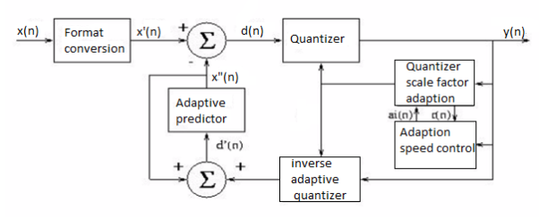
Fig. ADPCM Encoder
As most cellular applications demand a speech coder that can operate at under 8 kbps, even at 2-bit quantization ADPCM is considered to have high bandwidth demands. The relatively low complexity of ADPCM makes it attractive for systems, which require waveform preservation or have relaxed bandwidth restrictions. The latter of these fit cordless telephony and microcell applications well. The G.721 ADPCM has been specified in a few popular cordless standards. Great Britain introduced the CT2 system to address second generation cordless applications. The DECT, Digital European Cordless Telephony, system also covers second generation cordless, facilitating compatible systems across Europe. The third generation Personal Access Communication System, PACS, also specifies voice coding using 32 kbps ADPCM.
A source output is decomposed into its constituents. In each constituent is in afforded and decoded separately to improve compression performance. It separates the source output into bands of different frequency using digital filters. Different filters are used like low pass filter, high Pass filter.
A system that blocks certain frequency components is called a filter. Filters that only pass components below certain frequency f0 are Low Pass filters. Filters that block all components by low frequency f0 are called High Pass filter. Filters that pass components that have frequency content above certain frequency f1 and below frequency f2 are called band pass filters.
It consists of 3 phases
1) Analysis
2) Quantization and coding
3) Synthesis
Source output is pass through entire, non overlapping or overlapping filters. The range of frequency at the foot is less than the range of frequency at the input to the filter. The process of reducing the number of samples is called decimation or down sampling. The amount of decimation depends on the ratio of bandwidth of the filter output. To filter input. The bandwidth of the filter output is 1/M the bandwidth of filter input. Then the decimation will be of M.
Quantization and Coding
Allocation of beats between the submits is the main issue. Bits are located according to the measure of information content between sub and. When the information content of bands is very different, bit allocation procedure has a significant impact.
Synthesis
Quantised and coded coefficients are used for the construction of the original signal. From its urban common code. Examples for decoded at the receiver. Decoded values Aaron sampled by inserting an appropriate number of zeros between samples. The UNSAMPLED signals are pass through Bank of Reconstruction filter when the number of samples for second has been brought back to the original red. Summation of the reconstruction filter gives the final reconstructed output.
In order to maintain acceptable quality below the 8 kbps data rate, a fundamentally different approach to speech coding and sizeable jump in complexity is encountered. The most widely documented scheme for speech coding operating at under 8 kbps is CELP, code excited linear prediction. CELP actually represents a class of vocoders, all computationally expensive, which are based on the analysis and synthesis of incoming speech. The scope of this project limits the focus on one variation of CELP, and for the purpose of example and demonstration, this project focuses on the U.S. Federal Standard 1016 that defines a CELP algorithm operating at 4.8 kbps.
Opposed to waveform encoding, the goal of CELP algorithms is to code and transmit the minimal amount of information necessary to synthesize speech which is audibly perceived to be accurate. This is achieved by modeling aspects of the speech generation process, effectively modeling the vocal tract. Two components are generally found in these models, one which models the long term speech structure, the pitch, and another, which models the short-term speech structure, the formant. Relying on human perception as the measure of quality makes measurements of SNR irrelevant, and the overall rating of a specific implementation is in terms of mean opinion score, or MOS.
The technique of incorporating synthesis as a fundamental part of signal analysis is common to CELP algorithms and is why they are often referred to as analysis-by-synthesis techniques. Another departure from ADPCM, CELP algorithms work on frames of sampled input speech. The length and duration of the frame depends on the specific CELP algorithm. USFS-1016 operates on 30 ms frames which are furthure split into four 7.5 ms subframes.
Termed vector quantization, the frames of sampled input speech, input vectors, are compared to an existing set of excitation vectors called the code book. The search for the code book entry which produces the closest match is often an exhaustive search, making this class of algorithms computationally expensive. Each code book entry is applied to an LPC filter to generate a synthesized speech vector.
The synthesized sample is compared to with the input vector and rated with a perceptual weighing filter. The index of the code book with the vector producing the closest perceptual match to the input vector is selected and transmitted. Low bit rates are achieved because only the code book indices, LPC filter coefficients, and gain information are transmitted. Figure below, adapted, shows the block diagram for the USFS-1016 CELP encoder. Two code books and a 10th order LPC filter are used in USFS-1016. The 256 entry adaptive code book models the long-term speech structure, and the 10th order LPC filter models the short term speech structure. The residual signal remaining after adaptive code book quantization and LPC synthesis is modeled by the static 512 entry stochastic code.
The encoder transmits the index and gain for both stochastic and adaptive code books each subframe, or four times per 30 ms frame. The LPC filter coefficients are transmitted only once per frame. Modeling the long-term speech by the 256 entry adaptive code book improves quality at the cost of additional computational load of the same complexity as the 512 entry stochastic code book look-up. At the expense of quality, bit rates below 4.8 kbps can be achieved by limiting the search of the stochastic code book. Disadvantages associated with USFS-1016 CELP include the less than toll quality speech (3.2 MOS), and high processing delays (90 ms).
The frame-by-frame analysis, coupled with the high processing demands introduces delay which can degrade quality of conversation and introduce difficulties in related speech processing components, such as echo canceling. Other standards have been introduced which addressed both of these issues. Important standards often referenced in current literature include CCITT recommendation G.728 for LD-CELP, or low delay CELP, and G.729 for CS-ACELP, conjugate structure algebraic CELP. Both offer quality improvements but have higher bit rates (16 kbps and 8 kbps respectively). Less complex than LD-CELP, CS-ACELP operates at half the bit rate and offers toll quality speech. Yet another algorithm, VSELP, is defined in the IS-54 standard.
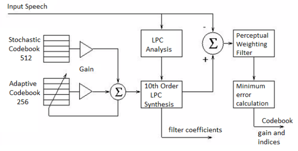
Fig. CELP Encoder
References:
1. Lathi B.P. - Modern Digital and Analog communications systems - PRISM Indian Ed.
2. Digital Communication: J.S.Chitode
3. Digital Communication (Fundamentals & applications): Bernard Scalr
4. Introduction to Error Control Codes: Salvatore Gravano
5. OFDM For wireless communication systems: Ramjee Prasad
6. Modern Communication systems (Principles and application): Leon W. Couch II (PHI)
7. Error Control Coding: Shu Lin & Daniel J.Costello