Unit - 4
Channel Coding (PART-1)
A finite field is also often known as a Galois field, after the French mathematician Pierre Galois. A Galois field in which the elements can take q different values is referred to as GF(q). The formal properties of a finite field are:
(a) There are two defined operations, namely addition and multiplication.
(b) The result of adding or multiplying two elements from the field is always an element in the field.
(c) One element of the field is the element zero, such that a + 0 = a for any element a in the field.
(d) One element of the field is unity, such that a • 1 = a for any element a in the field.
(e) For every element a in the field, there is an additive inverse element -a, such that a + (- a) = 0. This allows the operation of subtraction to be defined as addition of the inverse.
(f) For every non-zero element b in the field there is a multiplicative inverse element b -1 such that b b-1= 1. This allows the operation of division to be defined as multiplication by the inverse.
A field F is a set of elements with two operations + (addition) and multiplication satisfying the following properties
F is closed under + ie a +b and a.b are in F if a and b are in F.
For all a,band c in F the following hold :
Commutative law
a + b = b +a ,a.b = b.a
F if a and b are in F
Associative law
(a+b)+c = a+(b+c)
a.(b.c) = a.b+a.c
Distributive law
a.(b+c) = a.b + a.c
a+0 = a
a.1 =a
For any a in F there exists an additive inverse (-a) such that a + (-a) =0
For any a in F there exists a multiplicative inverse a -1 such that a -1 = 1
The above properties re true for fields with both finite as well as infinite elements. A field with finite number of elements q is called Galois Field denoted byGF(q)
In this section we present a method for constructing the Galois field of 2m elements (m > 1) from the binary field GF(2). We begin with the two elements 0 and I, from GF(2) and a new symbol α. Then we define a multiplication " •" to introduce a sequence of powers of as follows:
0.0 = 0
0.1 = 1.0 =0
1.1 =1
0.α = α.0 =0
1. α= α.1 = α
α2 = α. α
α3 = α. α. α
.
.
.
αj = α. α……. α (j times)
0 . αj = αj . 0 = 0,
1 . αj = αj . 1 = αj,
αi . αj = αj . αi = αi+j
Now, we have the following set of elements on which a multiplication operation "•" is defined:
F = { 0, 1, α, α2, . . ., αj, . . .}
Let p(X) be a primitive polynomial of degree m overGF(2). We assume that p (α) = 0. Since p(X)
Divides X2m-1+ 1,we have
X2m – 1 + 1 = q(X)p(X).
If we replace X by in above equation, we obtain
α2m-1 + 1 = q(α)p(α)
α2m-1 + 1 = q(α) . 0
If we regard q(α) as a polynomial of α over GF(2), it follows that q(α).0 = 0. As a result, we obtain the following equality:
α2m – 1+ 1 = 0
Adding 1 to both sides of above equation (use modulo-2 addition) results in the following equality:
α2m – 1 = 1
Therefore, the set F* (see above equation) is a Galois field of 2 m elements, GF(2m). Also, GF (2) is a subfield of GF(2m).
F* = {0, 1, α, α2, . . . , α2m – 2}
Examples
Let m = 4. The polynomial p(X) = 1 + X + X* is a primitive polynomial over GF(2). Set p(α) = 1 + + 4 = 0. Then α4 = 1 + α. Using this, we can construct GF(24). The elements of GF(24) are given in Table shown below. The identity α4 = 1 + α is used repeatedly to form the polynomial representations for the elements of GF(24). For example,
α5 = α . α4 = α(1+ α) = α + α2,
α6 = α . α5 = α(α + α2) = α2 + α3,
α7 = α . α6 = α(α2 + α3) = α3 + α4 = α3 + 1+α = 1+ α + α3
Power Representation | Polynomial Representation | 4-Tuple Representation |
0 | 0 | (0 0 0 0) |
1 | 1 | (1 0 0 0) |
α | α | (0 1 0 0) |
α2 | α2 | (0 0 1 0) |
α3 | α3 | (0 0 0 1) |
α4 | 1+α | (1 1 0 0) |
α5 | α+α2 | (0 1 1 0) |
α6 | α2+α3 | (0 0 1 1) |
α7 | 1+α +α3 | (1 1 0 1) |
α8 | 1 +α2 | (1 0 1 0) |
α9 | α +α3 | (0 1 0 1) |
α10 | 1+α+α2 | (1 1 1 0) |
α11 | α+α2+α3 | (0 1 1 1) |
α12 | 1+α+α2+α3 | (1 1 1 1) |
α13 | 1 +α2+α3 | (1 0 1 1) |
α14 | 1 +α3 | (1 0 0 1) |
To multiply two elements αi and αj, we simply add their exponents and use the fact that α15 = 1. For example, α5. α7 = α12 and α12.α7 =α19 =α4. Dividing αj by αiwe simply multiply αj by the multiplicative inverse α15-l of αl. For example, α4 /α12 =α4.α3 =α7
And α12 /α5 =α12. α10 =α22 =α7
α5 + α7 = (α + α2) + (1 + α + α3) = 1 + α2 + α3 = α13
1+ α5 + α10 = 1+ (α + α2) + (1 + α + α2) = 0
BASIC PROPERTIES OF GALOIS FIELD GF(2m)
In ordinary algebra we often see that a polynomial with real coefficients has roots not from the field of real numbers but from the field of complex numbers that contains the field of real numbers as a subfield. For example, the polynomial X2 + 6X + 25 does not have roots from the field of real numbers but has two complex conjugate roots, —3 + 4j and —3 — 4j, where j = √−1
This is also true for polynomials with coefficients from GF(2). In this case, a polynomial with coefficients from GF(2) may not have roots from GF(2) but has roots from an extension field of GF(2).
Example
For example, X4 + X3 + 1 is irreducible over GF(2) and therefore it does not have roots from GF(2). However, it has four roots from the field GF(24). If we substitute the elements of GF(24) given by Table into X4 + X3 + 1, we find that α7 , α11 , α13 , and α14 are the roots of X4 + X3 + 1. We may verify this as follows:
(α 7)4 + (α7)3+1 = α28 + α21+1 = (1+ α2+ α3) + (α2+ α3) +1=0
Indeed!α7 is a root X4 + X3 + 1. Similarly, we may verify that α11, α13, and α14 are the roots of X4 + X3 + 1. Then (X+α7) (X+α11) (X+α13) (X+α14) must be equal to X4 + X3 + 1. To see this, we multiply out the product above using table in previous question.
(X + α7)(X + α11)(X + α13)(X + α14) = [X2 + (α7 + α11)X + α18][X2 + (α13 + α14)X + α27]
= (X2 + α8X + α3)(X2 + α2X + α12)
= X4 + (α8 + α2)X3 + (α12 + α10 + α3)X2 + (α20 + α5)X + α15
= X4 + X3 + 1
Let f(X) be a polynomial with coefficients from GF(2). If  an element in GF(2m) is a root of f(X), the polynomial f(X) may have other roots from GF(2m). Then the roots are found as
Let f(X) be a polynomial with coefficients from GF(2). Let  be an element in an extension field of GF(2). If
  is a root of f(X), then for any l
 0,
0,  2l is also a root of f(X). The element
  2l is called the conjugate of
  .
.
The minimal polynomial (Φ(X) of a field element β is irreducible.
Forward Error Correction (FEC) is a technique used to minimize errors in data transmission over communication channels. In real-time multimedia transmission, re-transmission of corrupted and lost packets is not useful because it creates an unacceptable delay in reproducing: one needs to wait until the lost or corrupted packet is resent. Thus, there must be some technique which could correct the error or reproduce the packet immediately and give the receiver the ability to correct errors without needing a reverse channel to request re-transmission of data. There are various FEC techniques designed for this purpose.
These are as follows:
1. Using Hamming Distance:
For error correction, the minimum hamming distance required to correct t errors is:
dmin =2t+1
For example, if 20 errors are to be corrected then the minimum hamming distance has to be 2*20+1= 41 bits. This means, lots of redundant bits need to be sent with the data. This technique is very rarely used as we have large amount of data to be sent over the networks, and such a high redundancy cannot be afforded most of the time.
2. Using XOR:
The exclusive OR technique is quite useful as the data items can be recreated by this technique. The XOR property is used as follows –
R = P1 ⊕ P2 ⊕ . . . ⊕ Pi ⊕ . . . . PN Pi = P1 ⊕ P2 ⊕ . . . . ⊕ . . . R ⊕ . . . . PN
If the XOR property is applied on N data items, we can recreate any of the data items P1 to PN by exclusive-ORing all of the items, replacing the one to be created by the result of the previous operation(R). In this technique, a packet is divided into N chunks, and then the exclusive OR of all the chunks is created and then, N+1 chunks are sent. If any chunk is lost or corrupted, it can be recreated at the receiver side.
Practically, if N=4, it means that 25 percent extra data has to be sent and the data can be corrected if only one out of the four chunks is lost.
3. Chunk Interleaving:
In this technique, each data packet is divided into chunks. The data is then created chunk by chunk(horizontally) but the chunks are combined into packets vertically. This is done because by doing so, each packet sent carries a chunk from several original packets. If the packet is lost, we miss only one chunk in each packet, which is normally acceptable in multimedia communication. Some small chunks are allowed to be missing at the receiver. One chunk can be afforded to be missing in each packet as all the chunks from the same packet cannot be allowed to miss.
Automatic Repeat Request (ARQ) known as Automatic Repeat Query. It is an error control strategy used in a 2-way communication system. It is a group of error control protocols to achieve reliable data transmission over an unreliable source or service.
Flow Control:
In a communication network the two communicating entities will have different speed of transmission and reception. There will be problem if sender is faster than receiver.
The fast sender will swamp over the slow receiver. The “flow” of information between sender and receiver has to be “controlled”. The technique used for this is called flow control technique. Also, there will be time required to process incoming data at the receiver.
This time required for processing is often more than the time for transmission. Incoming data must be checked and processed before they can be used. Hence, we require a buffer at the receiver to store the received data. This buffer is limited, therefore, before it becomes full the sender has to be informed to halt transmission temporarily.
A set of procedures are required to be carried out to restrict the amount of data the sender can send before waiting for acknowledgement. This is called flow control.
Error Control:
When the data is transmitted it is going to be corrupted. We have seen how to tackle this problem by adding redundancy. Still the error is bound to occur. If such error occurs, the receiver can detect the errors and even correct them.
What we can do is if error is detected by receiver, it can ask the sender to retransmit the data. This process is called Automatic Repeat Request (ARQ). Thus, error control is based on ARQ, which is retransmission of data.
Protocols:
The functions of data link layer viz. Framing, error control and flow control are implemented in software. There are different protocols depending on the channel.
For noiseless channel, there are two protocols: (1) Simplest, (2) Stop-and-wait. For noisy channel, there are 3 protocols.
Stop and Wait ARQ (Simplex Protocol)
In this technique, transmitter (A) transmits a frame to receiver (B) and waits for an acknowledgement from B.
When acknowledgement from B is received, it transmits next frame.
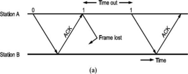
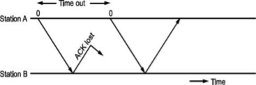
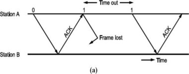
Now, consider a case where the frame is lost i.e., not received by B. B will not send an acknowledgement. A will wait and wait and wait to avoid this, we can start a timer at A, corresponding to a frame.
If the acknowledgement for a frame is not received within the time timer is on, we can retransmit the frame, as shown in Fig.
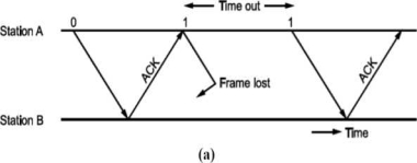
Same thing can happen when frame is in error and B does not send acknowledgement. After A times out it will retransmit.
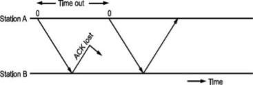
• There is another situation when some frame is transmitted but its acknowledgement is lost as shown in Fig.
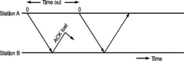
The time out will send the same frame again which will result into accepting duplicate frame at B. For this, we have to bring in the concept of sequence number to frames. In case a duplicate frame is received due to loss of Ack, it can be discarded.
A second ambiguity will arise due to delayed acknowledgement as shown in Fig.
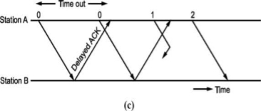
Fig: Stop and wait ARQ
As shown in figure, the acknowledgement received after frame 1 is transmitted would result into acknowledging frame 1 which is actually lost. We can give sequence number to acknowledgements so that transmitter knows the acknowledgement of which frame is received.
The acknowledgement number will be the number of next frames expected i.e., when frame 0 is received properly, we will be sending Acknowledgement number 1 as frame 1 is expected next.
Now, the next question is what should be the sequence numbers given to frame and acknowledgement. We cannot give large sequence numbers because they are going to occupy some space in frame header. Hence, sequence number should have minimum number of bits.
In Stop and wait ARQ (simplex) protocol, one bit sequence number is sufficient. For this consider that frame O is transmitted and the receiver receives and sends acknowledgement number 1. Now, frame 1 is transmitted and sends acknowledgement for it since frame O is already received. We can use same number for next frame as shown in Fig.
Frame O arises at B
ACK sent
(O, O) ► (0,1)
(1.0)— (1,1)
Frame 1 arises at B
ACK sent
• This ARQ technique is used in IBM's Binary Synchronous Communication (BISYNC) protocol and XMODEM, a file transfer protocol for modems.
Go-Back N ARQ
Unlike Stop and wait ARQ, in this technique transmitter continues sending frames without waiting for acknowledgement.
The transmitter keeps the frames which are transmitted in a buffer called sending window till its acknowledgement is received.
Let the number of frames transmitter can keep in its buffer be Ws. It is called size of sender's window.
The size of window is selected on the basis of delay-bandwidth product so that channel does not remain idle and efficiency is more.
The transmitter keeps on transmitting the frames in window (buffer), till acknowledgement for the first frame in the window is received.
When frames O to Ws - 1 are transmitted, the transmitter waits for acknowledgement of frame O. When it is received the next frame is taken from network layer into the buffer i.e., window slides forward by one frame.
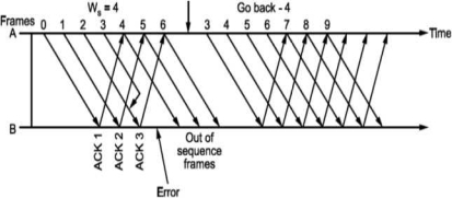
If acknowledgement for an expected frame (i.e., first frame in the window) does not reach back and time-out occurs for the frame, all the frames in the buffer are transmitted again. Since there are N = Ws frames waiting in the buffer, this technique is called Go back N ARQ.
Thus, Go back N ARQ pipelines the processing of frames to keep the channel busy.
Fig shows Go Back N ARQ.
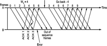
It can be seen that the receiver window size will be 1, since only one frame which is in order is accepted.
Also, the expected frame number at the receiver end is always less than or equal to recently transmitted frame.
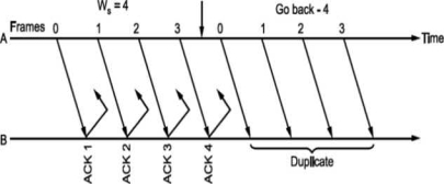
What should be the maximum window size at the transmitter i.e., what should be value of W S∙ It will depend on the number of bits used in sequence number field of the frame. So maximum window size at transmitter should be Ws = 2m i.e., if 3 bits are reserved for sequence number Ws = 8, but it will not! For this consider following situation shown in Fig.
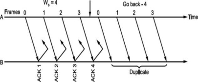
i.e., if all the frames transmitted are acknowledged or their acknowledgement is lost. The transmitter will retransmit the frames in the buffer. The receiver will accept them as if they are new frames! Hence, to avoid this problem, we reduce window size by 1 i.e., Ws = 2^ - 1 = 3 i.e., make it Goback3. But the sequence number is maintained from 0 to 3. Now consider Fig. (c), where the acknowledgements of all the received frames 0, 1, 2 are lost but the receiver is expecting frame 3. Hence, even if we transmit 0,1,2 again they will not be accepted as the expected sequence number does not match transmitted one. Hence, the window size should be 2m - 1 for Go Back N ARQ.
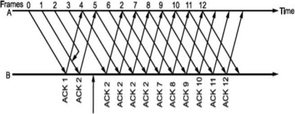
Go Back N can be implemented for both ends i.e., we can send information and acknowledgement together which is called piggybacking. This improves the use of bandwidth. Fig. (c) shows the scheme.
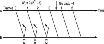
Fig -Go Back N ARQ
Note that both transmitter and receiver need sending and receiving windows. Go back N ARQ is implemented in HDLC protocol and V-24 modem standard
Selective Repeat ARQ
Go Back N ARQ is inefficient when channels have high error rates.
Instead of transmitting all the frames in buffer, we can transmit only the frame in error.
For this, we have to increase the window size of receiver so that it can accept frames which are error free but out of order (not in sequence).
Normally, when an acknowledgement for first frame is received, the transmit window is advanced. Similarly, whenever acknowledgement for the first frame in receiver window is sent it advances.
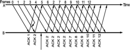
Whenever there is error or loss of frame and no acknowledgement is sent, the transmitter retransmits the frame whenever its timer expires. The receiver whenever accepts next frame which is out of sequence now sends negative acknowledgement NAK corresponding to the frame number it is expecting. Till the time the frame is received it keeps on accumulating frames received in the receiver window. Then, it sends the acknowledgement of recently accepted frame that was in error. It is shown in Fig. Below.
To calculate the window size for given sequence numbering having m
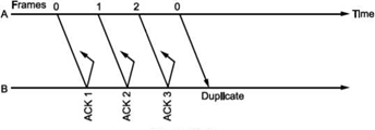
Bits, consider the situation shown in Fig.
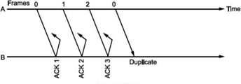
Let us select window size for m = 2 as Ws = 2m -1=3. Let the frames 0, 1, 2 be in the buffer and are transmitted. They are received correctly but their acknowledgements are lost. Timer for frame 0 expires, hence is retransmitted. The receiver window is expecting frame 0 which it accepts as new frame but actually, it is duplicate!

Fig. Selective Repeat ARQ
Thus, the window size at transmitter and receiver are too large. Hence, we select Ws = Wr = 2m∕2 = 2m-l. In above case, Ws = Wr = 2⅜ = 2. Sequence numbers for frames will be 0, 1, 2, 3, as shown in Fig. 2.19 (c). The transmitter transmits frames 0, 1. But because of lost acknowledgements, timer for frame 0 expires. Hence, it retransmits frame 0. At the receiver we have expected frames {2, 3}. Hence, frame 0 is rejected as it is duplicate and not part of receiver window.
The selective repeat ARQ is used in TCP (Transmission Control Protocol) and SSCOP (Service Specific Connection Oriented Protocol).
The protocols discussed here assume that the data flows only in one direction from sender to receiver. In practice, however, it is bidirectional. Hence, when the flow is bidirectional, we will be using piggybacking i.e., sending acknowledgement (positive/ negative) along with data if any to be sent to the other end.
Error Detection and Correction
Whenever bits flow from one point to another, they are subjected to unpredictable changes, because of interference. This interference can change the shape of signals. In a single bit error aθ is changed to al or al to aθ. In a burst error, multiple bits are changed. For example, 1/1 OOs burst of impulse noise on a transmission with a data rate of 1200 bps might change all or some of the 12 bits of information.
Single Bit Error: It means that only 1 bit of a given data unit (as a byte, character or packet) is changed from 1 to 0 or 0 to 1.
Below figure shows the effect of single bit error on a data unit. To understand the impact of change, imagine that each group of 8 bits is an ASCII character with aθ bit added to the left. In Fig. 2.7, 00000010 (ASCII/STX) was sent, meaning start of text but 00001010 (ASCII LF) was received, meaning line feed.

Sent Received
Single bit errors are the least likely type of errors in serial data transmission. To understand imagine data sent at 1 Mbps. This means that each bit lasts only 1/1,000,000s or 1 μs. For single bit error to occur, the noise must have a duration of only 1 μs, which is very rare. Noise normally lasts much longer than this.
Burst Error: The term means that 2 or more bits in the data unit have changed from 1 to 0 or from 0 to 1.

In this case 0100010001000011 was sent, but 0101110101100011 was received. A burst error does not necessarily mean that the errors occur in consecutive bits. The length of the burst is measured from the first corrupted bit to the last corrupted bit. Some bits in between may not have been corrupted.
A burst error is more likely to occur than a single bit error. The duration of noise is normally longer than the duration of 1 bit, this means when noise affects data, it affects a set of bits. The number of bits affected depends on the data rate and duration of noise. For example, if we are sending data at 1 kbps, a noise of 1/1 OOs can affect 10 bits, if we are sending data at 1 Mbps, the same noise can affect 10,000 bits.
Redundancy:
The main concept in detecting errors is redundancy. To detect errors, we need to send some extra bits with our data. These redundant bits are added by sender and removed by the receiver. Their presence allows the receiver to detect corrupted bits.
Detection Versus Correction:
The correction of error is more difficult than detection. In error detection, we are looking only to see if any error has occurred. The answer is a simple yes or no. We are not even interested in the number of errors. A single bit error is the same for us as a burst error.
In error correction, we need to know the exact number of bits that are corrupted and more importantly, their location in the message. The number of errors and the size of the message are important factors. If we need to correct one single error in an 8-bit data unit. We need to consider eight possible error locations. If we need to correct two errors in data unit of the same size, we need to consider 28 possibilities. You can imagine the receiver’s difficulty in finding 10 errors in data unit of 1000 bits.
Forward Error Correction Versus Retransmission:
There are two main methods of error correction. Forward error correction is the process in which the receiver tries to guess the message by using redundant bits. This is possible, as we see later, if the number of errors is small.
Correction by retransmission is a technique in which the receiver detects the occurrence of an error and asks the sender to resend the message. Resending is repeated until a message arrives that the receiver believes in error-free.
In block coding, the encoder accepts a k-bit message block and generates an n-bit code word. Thus, code words are produced on a block-by-block basis. Therefore, a buffer is required in the encoder to place the message block. A subclass of Tree codes is convolutional codes. The convolutional encoder accepts the message bits continuously and generates the encoded codeword sequence continuously. Hence there is no need for buffer. But in convolutional codes, memory is required to implement the encoder.
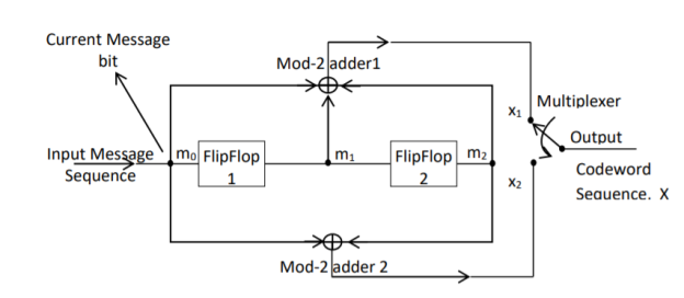
Fig: Convolutional Encoder
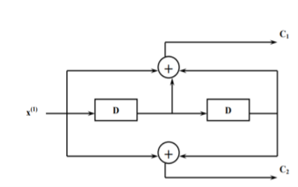
In a convolutional code, the encoding operation is the discrete-time convolution of the input data sequence with the impulse response of the encoder. The input message bits are stored in the fixed length shift register and they are combined with the help of mod-2 adders. This operation is equivalent to binary convolution and hence it is called convolutional coding. The figure above shows the connection diagram for an example convolutional encoder.
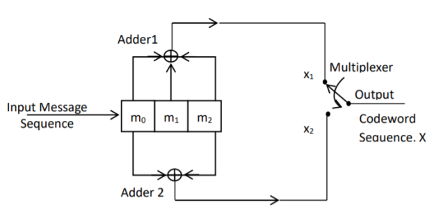
Fig: Convolutional Encoder redrawn alternatively
The encoder of a binary convolution code may be viewed as a finite-state machine. It consists of M-stage shift register with prescribed connections to modulo2 adders. A multiplexer serializes the outputs of the adders. The convolutional codes generated by these encoders of Figure above are non-systematic form. Consider that the current message bit is shifted to position m0. Then m1 and m2 store the previous two message bits. Now, by mod-2 adders 1 and 2 we get the new values of X1 and X2. We can write
X1 = m0 m1 m2 and
X2 = m0 m2
The multiplexer switch first samples X1 and then X2. Then next input bit is taken and stored in m0. The shift register then shifts the bit already in m0 to m1. The bit already in m1 is shifted to m2. The bit already in m2 is discarded. Again, X1 and X2 are generated according to this new combination of m0, m1 and m2. This process is repeated for each input message bit. Thus, the output bit stream for successive input bits will be,
X = x1 x2 x1 x2 x1 x2…….. And so on
In this convolutional encoder, for every input message bit, two encoded output bits X1 and X2 are transmitted. Hence number of message bits, k = 1. The number of encoded output bits for one message bit, n = 2.
Code rate: The code rate of this convolutional encoder is given by
Code rate, r = 𝑀𝑒𝑠𝑠𝑎𝑔𝑒𝑏𝑖𝑡𝑠 (𝑘)/𝑒𝑛𝑐𝑜𝑑𝑒𝑟𝑜𝑢𝑡𝑝𝑢𝑡𝑏𝑖𝑡𝑠 (𝑛) = 𝑘/𝑛 = 1/2 where 0 < r < 1
Constraint Length: The constraint length (K) of a convolution code is defined as the number of shifts over which a single message bit can influence the encoder output. It is expressed in terms of message bits. For the encoder of Figure above, constraint length is K = 3 bits. Because, a single message bit influences encoder output for three successive shifts. At the fourth shift, the message bit is lost and it has no effect on the output. For the encoder of Figure above, whenever a particular message bit enters the shift register, it remains in the shift register for three shifts ie.,
First Shift → Message bit is entered in position m0.
Second Shift → Message bit is shifted in position m1.
Third Shift → Message bit is shifted in position m2.
Constraint length ‘K’ is also equal to one plus the number of shift registers required to implement the encoder.
Dimension of the Code
The code dimension of a convolutional code depends on the number of message bits ‘k’, the number of encoder output bits, ‘n’ and its constraint length ‘K’. The code dimension is therefore represented by (n, k, K). For the encoder shown in figure above, the code dimension is given by (2, 1, 3) where n = 2, k = 1 and constraint length K = 3.
Graphical representation of convolutional codes
Convolutional code structure is generally presented in graphical form by the following three equivalent ways.
1. By means of the state diagram
2. By drawing the code trellis
3. By drawing the code tree
These methods can be better explained by using an example.
For the convolutional encoder given below in Figure, determine the following. a) Code rate b) Constraint length c) Dimension of the code d) Represent the encoder in graphical form.
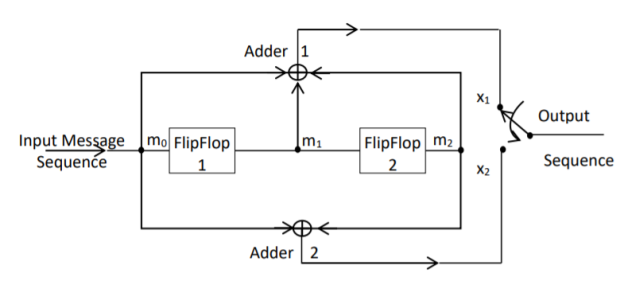
a) Code rate:
The code rate, r = 𝑘/𝑛. The number of message bits, k = 1.
The number of encoder output bits, n = 2.
Hence code rate, r = 1/2
b) Constraint length:
Constraint length, k = 1 + number of shift registers.
Hence k = 1 + 2 = 3
c) Code dimension:
Code dimension = (n, k,K) = (2, 1, 3)
Hence the given encoder is of ½ rate convolutional encoder of dimension (2, 1, 3).
d) Graphical form representation
The encoder output is X = (x1 x2 x1 x2 x1 x2….. And so on)
The Mod-2 adder 1 output is x1 = m0 m1 m2
The Mod-2 adder 2 output is x2 = m0 m2.
We can represent the encoder output for possible input message bits in the form of a Logic table.
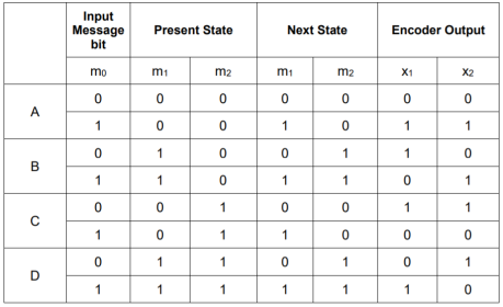
Output x1 = m0 m1 m2 and x2 = m0 m2
- The encoder output depends on the current input message bit and the contents in the shift register ie., the previous two bits.
- The present condition of the previous two bits in the shift register may be in four combinations. Let these combinations 00, 10, 01 and 11 be corresponds to the states A, B, C and D respectively.
- For each input message bit, the present state of the m1 and m2 bits will decide the encoded output.
- The logic table presents the encoded output x1 and x2 for the possible ‘0’ or ‘1’ bit input if the present state is A or B or C or D.
1. State diagram representation
- The state of a convolutional encoder is defined by the contents of the shift register. The number of states is given by 2k-1 = 23-1 = 22 = 4. Here K represents the constraint length.
- Let the four states be A = 00, B = 10, C = 01 and D = 11 as per the logic table. A state diagram as shown in the figure below illustrates the functioning of the encoder.
- Suppose that the contents of the shift register is in the state A = 00. At this state, if the incoming message bit is 0, the encoder output is X = (x1 x2) = 00. Then if the m0, m1 and m2 bits are shifted, the contents of the shift register will also be in state A = 00. This is represented by a solid line path starting from A and ending at A itself.
- At the ‘A’ state, if the incoming message bit is 1, then the encoder output is X = 11. Now if the m0, m1 and m2 bits are shifted, the contents of the shift register will become the state B = 10. This is represented by a dashed line path starting from A and ending at B.
- Similarly, we can draw line paths for all other states, as shown in the Figure below.
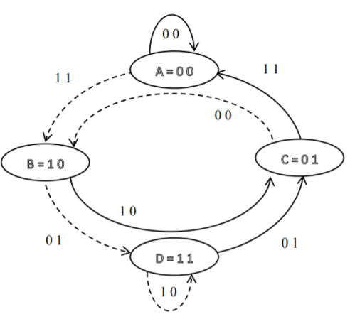
Fig: State Diagram
2. Code tree representation
- The code tree diagram is a simple way of describing the encoding procedure. By traversing the diagram from left to right, each tree branch depicts the encoder output codeword.
- Figure below shows the code representation for this encoder.
- The code tree diagram starts at state A =00. Each state now represents the node of a tree. If the input message bit is m0 = 0 at node A, then path of the tree goes upward towards node A and the encoder output is 00. Otherwise, if the input message bit is m0 = 1, the path of the tree goes down towards node B and the encoder output is 11.
- Similarly depending upon the input message bit, the path of the tree goes upward or downward. On the path between two nodes the outputs are shown.
- In the code tree, the branch pattern begins to repeat after third bit, since particular message bit is stored in the shift registers of the encoder for three shifts.
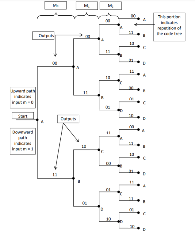
Fig: Code Tree Representation
3. Code trellis representation
- Code trellis is the more compact representation of the code tree. In the code tree there are four states (or nodes). Every state goes to some other state depending upon the input message bit.
- Code trellis represents the single and unique diagram for such steady state transitions. The Figure below shows the code trellis diagram.
- The nodes on the left denote four possible current states and those on the right represents next state. The solid transition line represents for input message m0 = 0 and dashed line represents input message m0 = 1.
- Along with each transition line, the encoder output x1 x2 is represented during that transition.
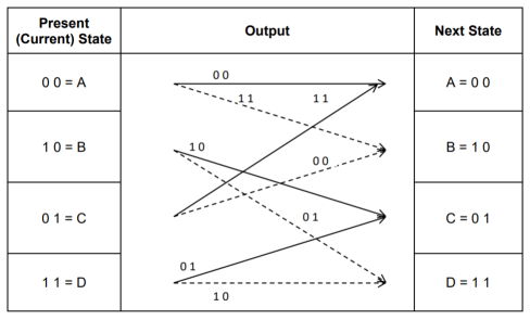
Fig: Code Trellis
Advantages of convolutional codes
- The convolutional codes operate on smaller blocks of data. Hence decoding delay is small.
- The storage hardware required is less.
Disadvantages of convolutional codes
- Due to complexity, the convolutional codes are difficult to analyze.
- These codes are not developed much as compared to block codes.
Key takeaway
Comparison between Linear Block codes and Convolutional codes
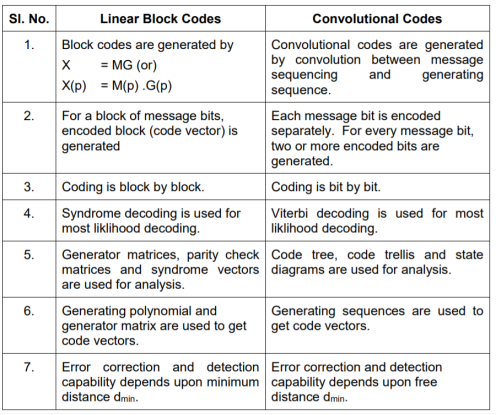
The Viterbi Algorithm (VA) finds a maximum likelihood (ML) estimate of a transmitted code sequence c from the corresponding received sequence r by maximizing the probability p(r|c) that sequence r is received conditioned on the estimated code sequence c. Sequence c must be a valid coded sequence. The Viterbi algorithm utilizes the trellis diagram to compute the path metrics. The channel is assumed to be memory less, i.e. the noise sample affecting a received bit is independent from the noise sample affecting the other bits. The decoding operation starts from state ‘00’, i.e. with the assumption that the initial state of the encoder is ‘00’.
With receipt of one noisy codeword, the decoding operation progresses by one step deeper into the trellis diagram. The branches, associated with a state of the trellis tell us about the corresponding codewords that the encoder may generate starting from this state. Hence, upon receipt of a codeword, it is possible to note the ‘branch metric’ of each branch by determining the Hamming distance of the received codeword from the valid codeword associated with that branch. Path metric of all branches, associated with all the states are calculated similarly.
Now, at each depth of the trellis, each state also carries some ‘accumulated path metric’, which is the addition of metrics of all branches that construct the ‘most likely path’ to that state. As an example, the trellis diagram of the code shown in Fig., has four states and each state has two incoming and two outgoing branches. At any depth of the trellis, each state can be reached through two paths from the previous stage and as per the VA, the path with lower accumulated path metric is chosen. In the process, the ‘accumulated path metric’ is updated by adding the metric of the incoming branch with the ‘accumulated path metric’ of the state from where the branch originated. No decision about a received codeword is taken from such operations and the decoding decision is deliberately delayed to reduce the possibility of erroneous decision. The basic operations which are carried out as per the hard-decision Viterbi Algorithm after receiving one codeword are summarized below:
a) All the branch metrics of all the states are determined;
b) Accumulated metrics of all the paths (two in our example code) leading to a state are calculated taking into consideration the ‘accumulated path metrics’ of the states from where the most recent branches emerged;
c) Only one of the paths, entering into a state, which has minimum ‘accumulated path metric’ is chosen as the ‘survivor path’ for the state (or, equivalently ‘node’);
d) So, at the end of this process, each state has one ‘survivor path’. The ‘history’ of a survivor path is also maintained by the node appropriately ( e.g. By storing the codewords or the information bits which are associated with the branches making the path)
e) Steps a) to d) are repeated and decoding decision is delayed till sufficient number of codewords has been received. Typically, the delay in decision making = Lx k codewords where L is an integer, e.g. 5 or 6. For the code in Fig. Above, the decision delay of 5x3 = 15 codewords may be sufficient for most occasions. This means, we decide about the first received codeword after receiving the 16th codeword. The decision strategy is simple.
Upon receiving the 16th codeword and carrying out steps a) to d), we compare the ‘accumulated path metrics’ of all the states ( four in our example) and chose the state with minimum overall ‘accumulated path metric’ as the ‘winning node’ for the first codeword. Then we trace back the history of the path associated with this winning node to identify the codeword tagged to the first branch of the path and declare this codeword as the most likely transmitted first codeword. The above procedure is repeated for each received codeword hereafter. Thus, the decision for a codeword is delayed but once the decision process starts, we decide once for every received codeword. For most practical applications, including delay-sensitive digital speech coding and transmission, a decision delay of Lx k codewords is acceptable.
Soft-Decision Viterbi Algorithm
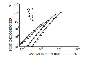
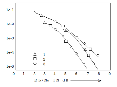
In soft-decision decoding, the demodulator does not assign a ‘0’ or a ‘1’ to each received bit but uses multi-bit quantized values. The soft-decision Viterbi algorithm is very similar to its hard-decision algorithm except that squared Euclidean distance is used in the branch metrics instead of simpler Hamming distance. However, the performance of a soft-decision VA is much more impressive compared to its HDD (Hard Decision Decoding) counterpart The computational requirement of a Viterbi decoder grows exponentially as a function of the constraint length and hence it is usually limited in practice to constraint lengths of K = 9.
Fano algorithm
Source encoding is a process in which the output of an information source is converted into a r-ary sequence where r is the number of different symbols used in this transformation process. The functional block that performs this task in a communication system is called source encoder.
The input to the encoder is the symbol sequence emitted by the information source and the output of the encoder is r-ary sequence.
If r=2 then it is called the binary sequence
r=3 then it is called ternary sequence
r=4 then it is called quarternary sequence.
Let the source alphabet S consist of “q” number of source symbols given by S = {S1,S2…….Sq} . Let another alphabet X called the code alphabet consists of “r” number of coding symbols given by
X = {X1,X2………………………Xr}
The term coding can now be defined as the transformation of the source symbols into some sequence of symbols from code alphabet X.
Shannon’s encoding algorithm
The following steps indicate the Shannon’s procedure for generating binary codes.
Step 1:
List the source symbols in the order of non-increasing probabilities
S = {S1,S2,S3……………………Sq} with P = {P1,P2,P3…………………..Pq}
P1 ≥P2 ≥P3 ≥………………….Pq
Step 2
Compute the sequences α + 1 = 0
α 2 = P 1= P1 + α 1
α 3= P2 + P1 = P2 + α 2
α 4 = P3+P2+P1 = P3 + α 3
….. ……..
α q+ 1 = Pq + Pq-1 +…………+ P2 + P1 = Pq + α q
Step 3:
Determine the smallest integer value of “li using the inequality
2 li ≥ 1/Pi for all i=1,2,……………………q.
Step 4:
Expand the decimal number αi in binary form upto li places neglecting expansion beyond li places.
Step 5:
Remove the binary point to get the desired code.
Example:
Apply Shannon’s encoding (binary algorithm) to the following set of messages and obtain code efficiency and redundancy.
m 1 | m 2 | m 3 | m 4 | m 5 |
1/8 | 1/16 | 3/16 | ¼ | 3/8 |
Step 1:
The symbols are arranged according to non-increasing probabilities as below:
m 5 | m 4 | m 3 | m 2 | m 1 |
3/8 | ¼ | 3/16 | 1/16 | 1/8 |
P 1 | P 2 | P 3 | P 4 | P 5 |
Step 2:
The following sequences of α are computed
α 1 = 0
α 2 = P1 + α 1 = 3/8 + 0 = 0.375
α 3 = P2 + α 2 = ¼ + 0.375 = 0.625
α 4 = P3 + α 3 = 3/16 + 0.625 = 0.8125
α 5 = P4 + α 4 = 1/16 + 0.8125 = 0.9375
α 6 = P5 + α 5 = 1/8 + 0.9375 = 1
Step 3:
The smallest integer value of li is found by using
2 li ≥ 1/Pi
For i=1
2 l1 ≥ 1/P1
2 l1 ≥ 1/3/8 = 8/3 = 2.66
The smallest value ofl1 which satisfies the above inequality is 2 therefore l1 = 2.
For i=2 2l2 ≥ 1/P2 Therefore 2 l2 ≥ 1/P2
2 l2 ≥ 4 therefore l2 = 2
For i =3 2 l3 ≥ 1/P3 Therefore 2 l3 ≥ 1/P3 2 l3 ≥ 1/ 3/16 = 16/3 l3 =3
For i=4 2l4 ≥ 1/P4 Therefore 2 l4 ≥ 1/P4
2 l4 ≥ 8 Therefore l4 = 3
For i=5
2 l5 ≥ 1/P5 Therefore
2 l5 ≥ 16 Therefore l5=4
Step 4:
The decimal numbers αi are expanded in binary form upto li places as given below.
α 1 = 0
α 2 = 0.375
0.375 x2 = 0.750 with carry 0
0.75 x 2 = 0.50 with carry 1
0.50 x 2 = 0.0 with carry 1
Therefore
(0.375) 10 = (0.11)2
α 3 = 0.625
0.625 X 2 = 0.25 with carry 1
0.25 X 2 = 0.5 with carry 0
0.5 x 2 = 0.0 with carry 1
(0.625) 10 = (0.101)2
α 4 = 0.8125
0.8125 x 2 = 0.625 with carry 1
0.625 x 2 = 0.25 with carry 1
0.25 x 2 = 0. 5 with carry 0
0.5 x 2 = 0.0 with carry 1
(0.8125) 10 = (0.1101)2
α 5 = 0.9375
0.9375 x 2 = 0.875 with carry 1
0.875 x 2 = 0.75 with carry 1
0.75 x 2 = 0.5 with carry 1
0.5 x 2 = 0.0 with carry 1
(0.9375) 10 = (0.1111)2
α 6 = 1
Step 5:
α 1 = 0 and l1 = 2 code for S1 ----00
α 2 =(0.011) 2 and l2 =2 code for S2 ---- 01
α 3 = (.101)2 and l3 =3 code for S3 ------- 101
α 4 = (.1101)2 and l4 =3 code for S ----- 110
α 5 = (0.1111)2 and l5 = 4 code for s5 --- 1111
The average length is computed by using
L = 
= 3/8 x 2 + ¼ x 2 + 3/16 x 3 + 1/8 x 3 + 1/16 x 4
L= 2.4375 bits/msg symbol
The entropy is given by
H(s) = 3/8 log (8/3) + ¼ log 4 + 3/16 log 16/3 + 1/8 log 8 + 1/16 log 16
H(s) =2.1085 bits/msg symbol.
Code efficiency is given by
c = H(s)/L = 2.1085/2.4375 = 0.865
Percentage code efficiency = 86.5% c
Code redundancy
R c = 1 - c = 0.135 or 13.5%.
References:
1. Lathi B.P. - Modern Digital and Analog communications systems - PRISM Indian Ed.
2. Digital Communication: J.S.Chitode
3. Digital Communication (Fundamentals & applications): Bernard Scalr
4. Introduction to Error Control Codes: Salvatore Gravano
5. OFDM For wireless communication systems: Ramjee Prasad
6. Modern Communication systems (Principles and application): Leon W. Couch II (PHI)
7. Error Control Coding: Shu Lin & Daniel J.Costello
Unit - 4
Channel Coding (PART-1)
A finite field is also often known as a Galois field, after the French mathematician Pierre Galois. A Galois field in which the elements can take q different values is referred to as GF(q). The formal properties of a finite field are:
(a) There are two defined operations, namely addition and multiplication.
(b) The result of adding or multiplying two elements from the field is always an element in the field.
(c) One element of the field is the element zero, such that a + 0 = a for any element a in the field.
(d) One element of the field is unity, such that a • 1 = a for any element a in the field.
(e) For every element a in the field, there is an additive inverse element -a, such that a + (- a) = 0. This allows the operation of subtraction to be defined as addition of the inverse.
(f) For every non-zero element b in the field there is a multiplicative inverse element b -1 such that b b-1= 1. This allows the operation of division to be defined as multiplication by the inverse.
A field F is a set of elements with two operations + (addition) and multiplication satisfying the following properties
F is closed under + ie a +b and a.b are in F if a and b are in F.
For all a,band c in F the following hold :
Commutative law
a + b = b +a ,a.b = b.a
F if a and b are in F
Associative law
(a+b)+c = a+(b+c)
a.(b.c) = a.b+a.c
Distributive law
a.(b+c) = a.b + a.c
a+0 = a
a.1 =a
For any a in F there exists an additive inverse (-a) such that a + (-a) =0
For any a in F there exists a multiplicative inverse a -1 such that a -1 = 1
The above properties re true for fields with both finite as well as infinite elements. A field with finite number of elements q is called Galois Field denoted byGF(q)
In this section we present a method for constructing the Galois field of 2m elements (m > 1) from the binary field GF(2). We begin with the two elements 0 and I, from GF(2) and a new symbol α. Then we define a multiplication " •" to introduce a sequence of powers of as follows:
0.0 = 0
0.1 = 1.0 =0
1.1 =1
0.α = α.0 =0
1. α= α.1 = α
α2 = α. α
α3 = α. α. α
.
.
.
αj = α. α……. α (j times)
0 . αj = αj . 0 = 0,
1 . αj = αj . 1 = αj,
αi . αj = αj . αi = αi+j
Now, we have the following set of elements on which a multiplication operation "•" is defined:
F = { 0, 1, α, α2, . . ., αj, . . .}
Let p(X) be a primitive polynomial of degree m overGF(2). We assume that p (α) = 0. Since p(X)
Divides X2m-1+ 1,we have
X2m – 1 + 1 = q(X)p(X).
If we replace X by in above equation, we obtain
α2m-1 + 1 = q(α)p(α)
α2m-1 + 1 = q(α) . 0
If we regard q(α) as a polynomial of α over GF(2), it follows that q(α).0 = 0. As a result, we obtain the following equality:
α2m – 1+ 1 = 0
Adding 1 to both sides of above equation (use modulo-2 addition) results in the following equality:
α2m – 1 = 1
Therefore, the set F* (see above equation) is a Galois field of 2 m elements, GF(2m). Also, GF (2) is a subfield of GF(2m).
F* = {0, 1, α, α2, . . . , α2m – 2}
Examples
Let m = 4. The polynomial p(X) = 1 + X + X* is a primitive polynomial over GF(2). Set p(α) = 1 + + 4 = 0. Then α4 = 1 + α. Using this, we can construct GF(24). The elements of GF(24) are given in Table shown below. The identity α4 = 1 + α is used repeatedly to form the polynomial representations for the elements of GF(24). For example,
α5 = α . α4 = α(1+ α) = α + α2,
α6 = α . α5 = α(α + α2) = α2 + α3,
α7 = α . α6 = α(α2 + α3) = α3 + α4 = α3 + 1+α = 1+ α + α3
Power Representation | Polynomial Representation | 4-Tuple Representation |
0 | 0 | (0 0 0 0) |
1 | 1 | (1 0 0 0) |
α | α | (0 1 0 0) |
α2 | α2 | (0 0 1 0) |
α3 | α3 | (0 0 0 1) |
α4 | 1+α | (1 1 0 0) |
α5 | α+α2 | (0 1 1 0) |
α6 | α2+α3 | (0 0 1 1) |
α7 | 1+α +α3 | (1 1 0 1) |
α8 | 1 +α2 | (1 0 1 0) |
α9 | α +α3 | (0 1 0 1) |
α10 | 1+α+α2 | (1 1 1 0) |
α11 | α+α2+α3 | (0 1 1 1) |
α12 | 1+α+α2+α3 | (1 1 1 1) |
α13 | 1 +α2+α3 | (1 0 1 1) |
α14 | 1 +α3 | (1 0 0 1) |
To multiply two elements αi and αj, we simply add their exponents and use the fact that α15 = 1. For example, α5. α7 = α12 and α12.α7 =α19 =α4. Dividing αj by αiwe simply multiply αj by the multiplicative inverse α15-l of αl. For example, α4 /α12 =α4.α3 =α7
And α12 /α5 =α12. α10 =α22 =α7
α5 + α7 = (α + α2) + (1 + α + α3) = 1 + α2 + α3 = α13
1+ α5 + α10 = 1+ (α + α2) + (1 + α + α2) = 0
BASIC PROPERTIES OF GALOIS FIELD GF(2m)
In ordinary algebra we often see that a polynomial with real coefficients has roots not from the field of real numbers but from the field of complex numbers that contains the field of real numbers as a subfield. For example, the polynomial X2 + 6X + 25 does not have roots from the field of real numbers but has two complex conjugate roots, —3 + 4j and —3 — 4j, where j = √−1
This is also true for polynomials with coefficients from GF(2). In this case, a polynomial with coefficients from GF(2) may not have roots from GF(2) but has roots from an extension field of GF(2).
Example
For example, X4 + X3 + 1 is irreducible over GF(2) and therefore it does not have roots from GF(2). However, it has four roots from the field GF(24). If we substitute the elements of GF(24) given by Table into X4 + X3 + 1, we find that α7 , α11 , α13 , and α14 are the roots of X4 + X3 + 1. We may verify this as follows:
(α 7)4 + (α7)3+1 = α28 + α21+1 = (1+ α2+ α3) + (α2+ α3) +1=0
Indeed!α7 is a root X4 + X3 + 1. Similarly, we may verify that α11, α13, and α14 are the roots of X4 + X3 + 1. Then (X+α7) (X+α11) (X+α13) (X+α14) must be equal to X4 + X3 + 1. To see this, we multiply out the product above using table in previous question.
(X + α7)(X + α11)(X + α13)(X + α14) = [X2 + (α7 + α11)X + α18][X2 + (α13 + α14)X + α27]
= (X2 + α8X + α3)(X2 + α2X + α12)
= X4 + (α8 + α2)X3 + (α12 + α10 + α3)X2 + (α20 + α5)X + α15
= X4 + X3 + 1
Let f(X) be a polynomial with coefficients from GF(2). If  an element in GF(2m) is a root of f(X), the polynomial f(X) may have other roots from GF(2m). Then the roots are found as
Let f(X) be a polynomial with coefficients from GF(2). Let  be an element in an extension field of GF(2). If
  is a root of f(X), then for any l
 0,
0,  2l is also a root of f(X). The element
  2l is called the conjugate of
  .
.
The minimal polynomial (Φ(X) of a field element β is irreducible.
Forward Error Correction (FEC) is a technique used to minimize errors in data transmission over communication channels. In real-time multimedia transmission, re-transmission of corrupted and lost packets is not useful because it creates an unacceptable delay in reproducing: one needs to wait until the lost or corrupted packet is resent. Thus, there must be some technique which could correct the error or reproduce the packet immediately and give the receiver the ability to correct errors without needing a reverse channel to request re-transmission of data. There are various FEC techniques designed for this purpose.
These are as follows:
1. Using Hamming Distance:
For error correction, the minimum hamming distance required to correct t errors is:
dmin =2t+1
For example, if 20 errors are to be corrected then the minimum hamming distance has to be 2*20+1= 41 bits. This means, lots of redundant bits need to be sent with the data. This technique is very rarely used as we have large amount of data to be sent over the networks, and such a high redundancy cannot be afforded most of the time.
2. Using XOR:
The exclusive OR technique is quite useful as the data items can be recreated by this technique. The XOR property is used as follows –
R = P1 ⊕ P2 ⊕ . . . ⊕ Pi ⊕ . . . . PN Pi = P1 ⊕ P2 ⊕ . . . . ⊕ . . . R ⊕ . . . . PN
If the XOR property is applied on N data items, we can recreate any of the data items P1 to PN by exclusive-ORing all of the items, replacing the one to be created by the result of the previous operation(R). In this technique, a packet is divided into N chunks, and then the exclusive OR of all the chunks is created and then, N+1 chunks are sent. If any chunk is lost or corrupted, it can be recreated at the receiver side.
Practically, if N=4, it means that 25 percent extra data has to be sent and the data can be corrected if only one out of the four chunks is lost.
3. Chunk Interleaving:
In this technique, each data packet is divided into chunks. The data is then created chunk by chunk(horizontally) but the chunks are combined into packets vertically. This is done because by doing so, each packet sent carries a chunk from several original packets. If the packet is lost, we miss only one chunk in each packet, which is normally acceptable in multimedia communication. Some small chunks are allowed to be missing at the receiver. One chunk can be afforded to be missing in each packet as all the chunks from the same packet cannot be allowed to miss.
Automatic Repeat Request (ARQ) known as Automatic Repeat Query. It is an error control strategy used in a 2-way communication system. It is a group of error control protocols to achieve reliable data transmission over an unreliable source or service.
Flow Control:
In a communication network the two communicating entities will have different speed of transmission and reception. There will be problem if sender is faster than receiver.
The fast sender will swamp over the slow receiver. The “flow” of information between sender and receiver has to be “controlled”. The technique used for this is called flow control technique. Also, there will be time required to process incoming data at the receiver.
This time required for processing is often more than the time for transmission. Incoming data must be checked and processed before they can be used. Hence, we require a buffer at the receiver to store the received data. This buffer is limited, therefore, before it becomes full the sender has to be informed to halt transmission temporarily.
A set of procedures are required to be carried out to restrict the amount of data the sender can send before waiting for acknowledgement. This is called flow control.
Error Control:
When the data is transmitted it is going to be corrupted. We have seen how to tackle this problem by adding redundancy. Still the error is bound to occur. If such error occurs, the receiver can detect the errors and even correct them.
What we can do is if error is detected by receiver, it can ask the sender to retransmit the data. This process is called Automatic Repeat Request (ARQ). Thus, error control is based on ARQ, which is retransmission of data.
Protocols:
The functions of data link layer viz. Framing, error control and flow control are implemented in software. There are different protocols depending on the channel.
For noiseless channel, there are two protocols: (1) Simplest, (2) Stop-and-wait. For noisy channel, there are 3 protocols.
Stop and Wait ARQ (Simplex Protocol)
In this technique, transmitter (A) transmits a frame to receiver (B) and waits for an acknowledgement from B.
When acknowledgement from B is received, it transmits next frame.
Now, consider a case where the frame is lost i.e., not received by B. B will not send an acknowledgement. A will wait and wait and wait to avoid this, we can start a timer at A, corresponding to a frame.
If the acknowledgement for a frame is not received within the time timer is on, we can retransmit the frame, as shown in Fig.
Same thing can happen when frame is in error and B does not send acknowledgement. After A times out it will retransmit.
• There is another situation when some frame is transmitted but its acknowledgement is lost as shown in Fig.
The time out will send the same frame again which will result into accepting duplicate frame at B. For this, we have to bring in the concept of sequence number to frames. In case a duplicate frame is received due to loss of Ack, it can be discarded.
A second ambiguity will arise due to delayed acknowledgement as shown in Fig.
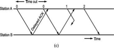
Fig: Stop and wait ARQ
As shown in figure, the acknowledgement received after frame 1 is transmitted would result into acknowledging frame 1 which is actually lost. We can give sequence number to acknowledgements so that transmitter knows the acknowledgement of which frame is received.
The acknowledgement number will be the number of next frames expected i.e., when frame 0 is received properly, we will be sending Acknowledgement number 1 as frame 1 is expected next.
Now, the next question is what should be the sequence numbers given to frame and acknowledgement. We cannot give large sequence numbers because they are going to occupy some space in frame header. Hence, sequence number should have minimum number of bits.
In Stop and wait ARQ (simplex) protocol, one bit sequence number is sufficient. For this consider that frame O is transmitted and the receiver receives and sends acknowledgement number 1. Now, frame 1 is transmitted and sends acknowledgement for it since frame O is already received. We can use same number for next frame as shown in Fig.
Frame O arises at B
ACK sent
(O, O) ► (0,1)
(1.0)— (1,1)
Frame 1 arises at B
ACK sent
• This ARQ technique is used in IBM's Binary Synchronous Communication (BISYNC) protocol and XMODEM, a file transfer protocol for modems.
Go-Back N ARQ
Unlike Stop and wait ARQ, in this technique transmitter continues sending frames without waiting for acknowledgement.
The transmitter keeps the frames which are transmitted in a buffer called sending window till its acknowledgement is received.
Let the number of frames transmitter can keep in its buffer be Ws. It is called size of sender's window.
The size of window is selected on the basis of delay-bandwidth product so that channel does not remain idle and efficiency is more.
The transmitter keeps on transmitting the frames in window (buffer), till acknowledgement for the first frame in the window is received.
When frames O to Ws - 1 are transmitted, the transmitter waits for acknowledgement of frame O. When it is received the next frame is taken from network layer into the buffer i.e., window slides forward by one frame.
If acknowledgement for an expected frame (i.e., first frame in the window) does not reach back and time-out occurs for the frame, all the frames in the buffer are transmitted again. Since there are N = Ws frames waiting in the buffer, this technique is called Go back N ARQ.
Thus, Go back N ARQ pipelines the processing of frames to keep the channel busy.
Fig shows Go Back N ARQ.
It can be seen that the receiver window size will be 1, since only one frame which is in order is accepted.
Also, the expected frame number at the receiver end is always less than or equal to recently transmitted frame.
What should be the maximum window size at the transmitter i.e., what should be value of W S∙ It will depend on the number of bits used in sequence number field of the frame. So maximum window size at transmitter should be Ws = 2m i.e., if 3 bits are reserved for sequence number Ws = 8, but it will not! For this consider following situation shown in Fig.
i.e., if all the frames transmitted are acknowledged or their acknowledgement is lost. The transmitter will retransmit the frames in the buffer. The receiver will accept them as if they are new frames! Hence, to avoid this problem, we reduce window size by 1 i.e., Ws = 2^ - 1 = 3 i.e., make it Goback3. But the sequence number is maintained from 0 to 3. Now consider Fig. (c), where the acknowledgements of all the received frames 0, 1, 2 are lost but the receiver is expecting frame 3. Hence, even if we transmit 0,1,2 again they will not be accepted as the expected sequence number does not match transmitted one. Hence, the window size should be 2m - 1 for Go Back N ARQ.
Go Back N can be implemented for both ends i.e., we can send information and acknowledgement together which is called piggybacking. This improves the use of bandwidth. Fig. (c) shows the scheme.
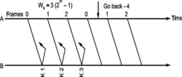
Fig -Go Back N ARQ
Note that both transmitter and receiver need sending and receiving windows. Go back N ARQ is implemented in HDLC protocol and V-24 modem standard
Selective Repeat ARQ
Go Back N ARQ is inefficient when channels have high error rates.
Instead of transmitting all the frames in buffer, we can transmit only the frame in error.
For this, we have to increase the window size of receiver so that it can accept frames which are error free but out of order (not in sequence).
Normally, when an acknowledgement for first frame is received, the transmit window is advanced. Similarly, whenever acknowledgement for the first frame in receiver window is sent it advances.
Whenever there is error or loss of frame and no acknowledgement is sent, the transmitter retransmits the frame whenever its timer expires. The receiver whenever accepts next frame which is out of sequence now sends negative acknowledgement NAK corresponding to the frame number it is expecting. Till the time the frame is received it keeps on accumulating frames received in the receiver window. Then, it sends the acknowledgement of recently accepted frame that was in error. It is shown in Fig. Below.
To calculate the window size for given sequence numbering having m
Bits, consider the situation shown in Fig.
Let us select window size for m = 2 as Ws = 2m -1=3. Let the frames 0, 1, 2 be in the buffer and are transmitted. They are received correctly but their acknowledgements are lost. Timer for frame 0 expires, hence is retransmitted. The receiver window is expecting frame 0 which it accepts as new frame but actually, it is duplicate!

Fig. Selective Repeat ARQ
Thus, the window size at transmitter and receiver are too large. Hence, we select Ws = Wr = 2m∕2 = 2m-l. In above case, Ws = Wr = 2⅜ = 2. Sequence numbers for frames will be 0, 1, 2, 3, as shown in Fig. 2.19 (c). The transmitter transmits frames 0, 1. But because of lost acknowledgements, timer for frame 0 expires. Hence, it retransmits frame 0. At the receiver we have expected frames {2, 3}. Hence, frame 0 is rejected as it is duplicate and not part of receiver window.
The selective repeat ARQ is used in TCP (Transmission Control Protocol) and SSCOP (Service Specific Connection Oriented Protocol).
The protocols discussed here assume that the data flows only in one direction from sender to receiver. In practice, however, it is bidirectional. Hence, when the flow is bidirectional, we will be using piggybacking i.e., sending acknowledgement (positive/ negative) along with data if any to be sent to the other end.
Error Detection and Correction
Whenever bits flow from one point to another, they are subjected to unpredictable changes, because of interference. This interference can change the shape of signals. In a single bit error aθ is changed to al or al to aθ. In a burst error, multiple bits are changed. For example, 1/1 OOs burst of impulse noise on a transmission with a data rate of 1200 bps might change all or some of the 12 bits of information.
Single Bit Error: It means that only 1 bit of a given data unit (as a byte, character or packet) is changed from 1 to 0 or 0 to 1.
Below figure shows the effect of single bit error on a data unit. To understand the impact of change, imagine that each group of 8 bits is an ASCII character with aθ bit added to the left. In Fig. 2.7, 00000010 (ASCII/STX) was sent, meaning start of text but 00001010 (ASCII LF) was received, meaning line feed.

Sent Received
Single bit errors are the least likely type of errors in serial data transmission. To understand imagine data sent at 1 Mbps. This means that each bit lasts only 1/1,000,000s or 1 μs. For single bit error to occur, the noise must have a duration of only 1 μs, which is very rare. Noise normally lasts much longer than this.
Burst Error: The term means that 2 or more bits in the data unit have changed from 1 to 0 or from 0 to 1.

In this case 0100010001000011 was sent, but 0101110101100011 was received. A burst error does not necessarily mean that the errors occur in consecutive bits. The length of the burst is measured from the first corrupted bit to the last corrupted bit. Some bits in between may not have been corrupted.
A burst error is more likely to occur than a single bit error. The duration of noise is normally longer than the duration of 1 bit, this means when noise affects data, it affects a set of bits. The number of bits affected depends on the data rate and duration of noise. For example, if we are sending data at 1 kbps, a noise of 1/1 OOs can affect 10 bits, if we are sending data at 1 Mbps, the same noise can affect 10,000 bits.
Redundancy:
The main concept in detecting errors is redundancy. To detect errors, we need to send some extra bits with our data. These redundant bits are added by sender and removed by the receiver. Their presence allows the receiver to detect corrupted bits.
Detection Versus Correction:
The correction of error is more difficult than detection. In error detection, we are looking only to see if any error has occurred. The answer is a simple yes or no. We are not even interested in the number of errors. A single bit error is the same for us as a burst error.
In error correction, we need to know the exact number of bits that are corrupted and more importantly, their location in the message. The number of errors and the size of the message are important factors. If we need to correct one single error in an 8-bit data unit. We need to consider eight possible error locations. If we need to correct two errors in data unit of the same size, we need to consider 28 possibilities. You can imagine the receiver’s difficulty in finding 10 errors in data unit of 1000 bits.
Forward Error Correction Versus Retransmission:
There are two main methods of error correction. Forward error correction is the process in which the receiver tries to guess the message by using redundant bits. This is possible, as we see later, if the number of errors is small.
Correction by retransmission is a technique in which the receiver detects the occurrence of an error and asks the sender to resend the message. Resending is repeated until a message arrives that the receiver believes in error-free.
Unit - 4
Channel Coding (PART-1)
A finite field is also often known as a Galois field, after the French mathematician Pierre Galois. A Galois field in which the elements can take q different values is referred to as GF(q). The formal properties of a finite field are:
(a) There are two defined operations, namely addition and multiplication.
(b) The result of adding or multiplying two elements from the field is always an element in the field.
(c) One element of the field is the element zero, such that a + 0 = a for any element a in the field.
(d) One element of the field is unity, such that a • 1 = a for any element a in the field.
(e) For every element a in the field, there is an additive inverse element -a, such that a + (- a) = 0. This allows the operation of subtraction to be defined as addition of the inverse.
(f) For every non-zero element b in the field there is a multiplicative inverse element b -1 such that b b-1= 1. This allows the operation of division to be defined as multiplication by the inverse.
A field F is a set of elements with two operations + (addition) and multiplication satisfying the following properties
F is closed under + ie a +b and a.b are in F if a and b are in F.
For all a,band c in F the following hold :
Commutative law
a + b = b +a ,a.b = b.a
F if a and b are in F
Associative law
(a+b)+c = a+(b+c)
a.(b.c) = a.b+a.c
Distributive law
a.(b+c) = a.b + a.c
a+0 = a
a.1 =a
For any a in F there exists an additive inverse (-a) such that a + (-a) =0
For any a in F there exists a multiplicative inverse a -1 such that a -1 = 1
The above properties re true for fields with both finite as well as infinite elements. A field with finite number of elements q is called Galois Field denoted byGF(q)
In this section we present a method for constructing the Galois field of 2m elements (m > 1) from the binary field GF(2). We begin with the two elements 0 and I, from GF(2) and a new symbol α. Then we define a multiplication " •" to introduce a sequence of powers of as follows:
0.0 = 0
0.1 = 1.0 =0
1.1 =1
0.α = α.0 =0
1. α= α.1 = α
α2 = α. α
α3 = α. α. α
.
.
.
αj = α. α……. α (j times)
0 . αj = αj . 0 = 0,
1 . αj = αj . 1 = αj,
αi . αj = αj . αi = αi+j
Now, we have the following set of elements on which a multiplication operation "•" is defined:
F = { 0, 1, α, α2, . . ., αj, . . .}
Let p(X) be a primitive polynomial of degree m overGF(2). We assume that p (α) = 0. Since p(X)
Divides X2m-1+ 1,we have
X2m – 1 + 1 = q(X)p(X).
If we replace X by in above equation, we obtain
α2m-1 + 1 = q(α)p(α)
α2m-1 + 1 = q(α) . 0
If we regard q(α) as a polynomial of α over GF(2), it follows that q(α).0 = 0. As a result, we obtain the following equality:
α2m – 1+ 1 = 0
Adding 1 to both sides of above equation (use modulo-2 addition) results in the following equality:
α2m – 1 = 1
Therefore, the set F* (see above equation) is a Galois field of 2 m elements, GF(2m). Also, GF (2) is a subfield of GF(2m).
F* = {0, 1, α, α2, . . . , α2m – 2}
Examples
Let m = 4. The polynomial p(X) = 1 + X + X* is a primitive polynomial over GF(2). Set p(α) = 1 + + 4 = 0. Then α4 = 1 + α. Using this, we can construct GF(24). The elements of GF(24) are given in Table shown below. The identity α4 = 1 + α is used repeatedly to form the polynomial representations for the elements of GF(24). For example,
α5 = α . α4 = α(1+ α) = α + α2,
α6 = α . α5 = α(α + α2) = α2 + α3,
α7 = α . α6 = α(α2 + α3) = α3 + α4 = α3 + 1+α = 1+ α + α3
Power Representation | Polynomial Representation | 4-Tuple Representation |
0 | 0 | (0 0 0 0) |
1 | 1 | (1 0 0 0) |
α | α | (0 1 0 0) |
α2 | α2 | (0 0 1 0) |
α3 | α3 | (0 0 0 1) |
α4 | 1+α | (1 1 0 0) |
α5 | α+α2 | (0 1 1 0) |
α6 | α2+α3 | (0 0 1 1) |
α7 | 1+α +α3 | (1 1 0 1) |
α8 | 1 +α2 | (1 0 1 0) |
α9 | α +α3 | (0 1 0 1) |
α10 | 1+α+α2 | (1 1 1 0) |
α11 | α+α2+α3 | (0 1 1 1) |
α12 | 1+α+α2+α3 | (1 1 1 1) |
α13 | 1 +α2+α3 | (1 0 1 1) |
α14 | 1 +α3 | (1 0 0 1) |
To multiply two elements αi and αj, we simply add their exponents and use the fact that α15 = 1. For example, α5. α7 = α12 and α12.α7 =α19 =α4. Dividing αj by αiwe simply multiply αj by the multiplicative inverse α15-l of αl. For example, α4 /α12 =α4.α3 =α7
And α12 /α5 =α12. α10 =α22 =α7
α5 + α7 = (α + α2) + (1 + α + α3) = 1 + α2 + α3 = α13
1+ α5 + α10 = 1+ (α + α2) + (1 + α + α2) = 0
BASIC PROPERTIES OF GALOIS FIELD GF(2m)
In ordinary algebra we often see that a polynomial with real coefficients has roots not from the field of real numbers but from the field of complex numbers that contains the field of real numbers as a subfield. For example, the polynomial X2 + 6X + 25 does not have roots from the field of real numbers but has two complex conjugate roots, —3 + 4j and —3 — 4j, where j = √−1
This is also true for polynomials with coefficients from GF(2). In this case, a polynomial with coefficients from GF(2) may not have roots from GF(2) but has roots from an extension field of GF(2).
Example
For example, X4 + X3 + 1 is irreducible over GF(2) and therefore it does not have roots from GF(2). However, it has four roots from the field GF(24). If we substitute the elements of GF(24) given by Table into X4 + X3 + 1, we find that α7 , α11 , α13 , and α14 are the roots of X4 + X3 + 1. We may verify this as follows:
(α 7)4 + (α7)3+1 = α28 + α21+1 = (1+ α2+ α3) + (α2+ α3) +1=0
Indeed!α7 is a root X4 + X3 + 1. Similarly, we may verify that α11, α13, and α14 are the roots of X4 + X3 + 1. Then (X+α7) (X+α11) (X+α13) (X+α14) must be equal to X4 + X3 + 1. To see this, we multiply out the product above using table in previous question.
(X + α7)(X + α11)(X + α13)(X + α14) = [X2 + (α7 + α11)X + α18][X2 + (α13 + α14)X + α27]
= (X2 + α8X + α3)(X2 + α2X + α12)
= X4 + (α8 + α2)X3 + (α12 + α10 + α3)X2 + (α20 + α5)X + α15
= X4 + X3 + 1
Let f(X) be a polynomial with coefficients from GF(2). If  an element in GF(2m) is a root of f(X), the polynomial f(X) may have other roots from GF(2m). Then the roots are found as
Let f(X) be a polynomial with coefficients from GF(2). Let  be an element in an extension field of GF(2). If
  is a root of f(X), then for any l
 0,
0,  2l is also a root of f(X). The element
  2l is called the conjugate of
  .
.
The minimal polynomial (Φ(X) of a field element β is irreducible.
Forward Error Correction (FEC) is a technique used to minimize errors in data transmission over communication channels. In real-time multimedia transmission, re-transmission of corrupted and lost packets is not useful because it creates an unacceptable delay in reproducing: one needs to wait until the lost or corrupted packet is resent. Thus, there must be some technique which could correct the error or reproduce the packet immediately and give the receiver the ability to correct errors without needing a reverse channel to request re-transmission of data. There are various FEC techniques designed for this purpose.
These are as follows:
1. Using Hamming Distance:
For error correction, the minimum hamming distance required to correct t errors is:
dmin =2t+1
For example, if 20 errors are to be corrected then the minimum hamming distance has to be 2*20+1= 41 bits. This means, lots of redundant bits need to be sent with the data. This technique is very rarely used as we have large amount of data to be sent over the networks, and such a high redundancy cannot be afforded most of the time.
2. Using XOR:
The exclusive OR technique is quite useful as the data items can be recreated by this technique. The XOR property is used as follows –
R = P1 ⊕ P2 ⊕ . . . ⊕ Pi ⊕ . . . . PN Pi = P1 ⊕ P2 ⊕ . . . . ⊕ . . . R ⊕ . . . . PN
If the XOR property is applied on N data items, we can recreate any of the data items P1 to PN by exclusive-ORing all of the items, replacing the one to be created by the result of the previous operation(R). In this technique, a packet is divided into N chunks, and then the exclusive OR of all the chunks is created and then, N+1 chunks are sent. If any chunk is lost or corrupted, it can be recreated at the receiver side.
Practically, if N=4, it means that 25 percent extra data has to be sent and the data can be corrected if only one out of the four chunks is lost.
3. Chunk Interleaving:
In this technique, each data packet is divided into chunks. The data is then created chunk by chunk(horizontally) but the chunks are combined into packets vertically. This is done because by doing so, each packet sent carries a chunk from several original packets. If the packet is lost, we miss only one chunk in each packet, which is normally acceptable in multimedia communication. Some small chunks are allowed to be missing at the receiver. One chunk can be afforded to be missing in each packet as all the chunks from the same packet cannot be allowed to miss.
Automatic Repeat Request (ARQ) known as Automatic Repeat Query. It is an error control strategy used in a 2-way communication system. It is a group of error control protocols to achieve reliable data transmission over an unreliable source or service.
Flow Control:
In a communication network the two communicating entities will have different speed of transmission and reception. There will be problem if sender is faster than receiver.
The fast sender will swamp over the slow receiver. The “flow” of information between sender and receiver has to be “controlled”. The technique used for this is called flow control technique. Also, there will be time required to process incoming data at the receiver.
This time required for processing is often more than the time for transmission. Incoming data must be checked and processed before they can be used. Hence, we require a buffer at the receiver to store the received data. This buffer is limited, therefore, before it becomes full the sender has to be informed to halt transmission temporarily.
A set of procedures are required to be carried out to restrict the amount of data the sender can send before waiting for acknowledgement. This is called flow control.
Error Control:
When the data is transmitted it is going to be corrupted. We have seen how to tackle this problem by adding redundancy. Still the error is bound to occur. If such error occurs, the receiver can detect the errors and even correct them.
What we can do is if error is detected by receiver, it can ask the sender to retransmit the data. This process is called Automatic Repeat Request (ARQ). Thus, error control is based on ARQ, which is retransmission of data.
Protocols:
The functions of data link layer viz. Framing, error control and flow control are implemented in software. There are different protocols depending on the channel.
For noiseless channel, there are two protocols: (1) Simplest, (2) Stop-and-wait. For noisy channel, there are 3 protocols.
Stop and Wait ARQ (Simplex Protocol)
In this technique, transmitter (A) transmits a frame to receiver (B) and waits for an acknowledgement from B.
When acknowledgement from B is received, it transmits next frame.
Now, consider a case where the frame is lost i.e., not received by B. B will not send an acknowledgement. A will wait and wait and wait to avoid this, we can start a timer at A, corresponding to a frame.
If the acknowledgement for a frame is not received within the time timer is on, we can retransmit the frame, as shown in Fig.
Same thing can happen when frame is in error and B does not send acknowledgement. After A times out it will retransmit.
• There is another situation when some frame is transmitted but its acknowledgement is lost as shown in Fig.
The time out will send the same frame again which will result into accepting duplicate frame at B. For this, we have to bring in the concept of sequence number to frames. In case a duplicate frame is received due to loss of Ack, it can be discarded.
A second ambiguity will arise due to delayed acknowledgement as shown in Fig.
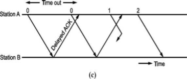
Fig: Stop and wait ARQ
As shown in figure, the acknowledgement received after frame 1 is transmitted would result into acknowledging frame 1 which is actually lost. We can give sequence number to acknowledgements so that transmitter knows the acknowledgement of which frame is received.
The acknowledgement number will be the number of next frames expected i.e., when frame 0 is received properly, we will be sending Acknowledgement number 1 as frame 1 is expected next.
Now, the next question is what should be the sequence numbers given to frame and acknowledgement. We cannot give large sequence numbers because they are going to occupy some space in frame header. Hence, sequence number should have minimum number of bits.
In Stop and wait ARQ (simplex) protocol, one bit sequence number is sufficient. For this consider that frame O is transmitted and the receiver receives and sends acknowledgement number 1. Now, frame 1 is transmitted and sends acknowledgement for it since frame O is already received. We can use same number for next frame as shown in Fig.
Frame O arises at B
ACK sent
(O, O) ► (0,1)
(1.0)— (1,1)
Frame 1 arises at B
ACK sent
• This ARQ technique is used in IBM's Binary Synchronous Communication (BISYNC) protocol and XMODEM, a file transfer protocol for modems.
Go-Back N ARQ
Unlike Stop and wait ARQ, in this technique transmitter continues sending frames without waiting for acknowledgement.
The transmitter keeps the frames which are transmitted in a buffer called sending window till its acknowledgement is received.
Let the number of frames transmitter can keep in its buffer be Ws. It is called size of sender's window.
The size of window is selected on the basis of delay-bandwidth product so that channel does not remain idle and efficiency is more.
The transmitter keeps on transmitting the frames in window (buffer), till acknowledgement for the first frame in the window is received.
When frames O to Ws - 1 are transmitted, the transmitter waits for acknowledgement of frame O. When it is received the next frame is taken from network layer into the buffer i.e., window slides forward by one frame.
If acknowledgement for an expected frame (i.e., first frame in the window) does not reach back and time-out occurs for the frame, all the frames in the buffer are transmitted again. Since there are N = Ws frames waiting in the buffer, this technique is called Go back N ARQ.
Thus, Go back N ARQ pipelines the processing of frames to keep the channel busy.
Fig shows Go Back N ARQ.
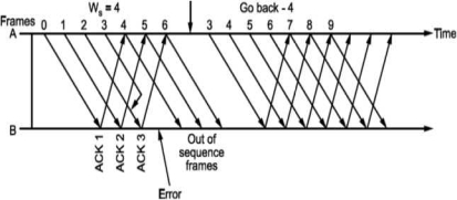
It can be seen that the receiver window size will be 1, since only one frame which is in order is accepted.
Also, the expected frame number at the receiver end is always less than or equal to recently transmitted frame.
What should be the maximum window size at the transmitter i.e., what should be value of W S∙ It will depend on the number of bits used in sequence number field of the frame. So maximum window size at transmitter should be Ws = 2m i.e., if 3 bits are reserved for sequence number Ws = 8, but it will not! For this consider following situation shown in Fig.
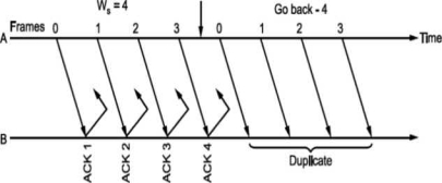
i.e., if all the frames transmitted are acknowledged or their acknowledgement is lost. The transmitter will retransmit the frames in the buffer. The receiver will accept them as if they are new frames! Hence, to avoid this problem, we reduce window size by 1 i.e., Ws = 2^ - 1 = 3 i.e., make it Goback3. But the sequence number is maintained from 0 to 3. Now consider Fig. (c), where the acknowledgements of all the received frames 0, 1, 2 are lost but the receiver is expecting frame 3. Hence, even if we transmit 0,1,2 again they will not be accepted as the expected sequence number does not match transmitted one. Hence, the window size should be 2m - 1 for Go Back N ARQ.
Go Back N can be implemented for both ends i.e., we can send information and acknowledgement together which is called piggybacking. This improves the use of bandwidth. Fig. (c) shows the scheme.
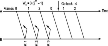
Fig -Go Back N ARQ
Note that both transmitter and receiver need sending and receiving windows. Go back N ARQ is implemented in HDLC protocol and V-24 modem standard
Selective Repeat ARQ
Go Back N ARQ is inefficient when channels have high error rates.
Instead of transmitting all the frames in buffer, we can transmit only the frame in error.
For this, we have to increase the window size of receiver so that it can accept frames which are error free but out of order (not in sequence).
Normally, when an acknowledgement for first frame is received, the transmit window is advanced. Similarly, whenever acknowledgement for the first frame in receiver window is sent it advances.
Whenever there is error or loss of frame and no acknowledgement is sent, the transmitter retransmits the frame whenever its timer expires. The receiver whenever accepts next frame which is out of sequence now sends negative acknowledgement NAK corresponding to the frame number it is expecting. Till the time the frame is received it keeps on accumulating frames received in the receiver window. Then, it sends the acknowledgement of recently accepted frame that was in error. It is shown in Fig. Below.
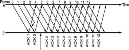
To calculate the window size for given sequence numbering having m
Bits, consider the situation shown in Fig.
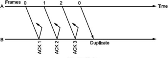
Let us select window size for m = 2 as Ws = 2m -1=3. Let the frames 0, 1, 2 be in the buffer and are transmitted. They are received correctly but their acknowledgements are lost. Timer for frame 0 expires, hence is retransmitted. The receiver window is expecting frame 0 which it accepts as new frame but actually, it is duplicate!

Fig. Selective Repeat ARQ
Thus, the window size at transmitter and receiver are too large. Hence, we select Ws = Wr = 2m∕2 = 2m-l. In above case, Ws = Wr = 2⅜ = 2. Sequence numbers for frames will be 0, 1, 2, 3, as shown in Fig. 2.19 (c). The transmitter transmits frames 0, 1. But because of lost acknowledgements, timer for frame 0 expires. Hence, it retransmits frame 0. At the receiver we have expected frames {2, 3}. Hence, frame 0 is rejected as it is duplicate and not part of receiver window.
The selective repeat ARQ is used in TCP (Transmission Control Protocol) and SSCOP (Service Specific Connection Oriented Protocol).
The protocols discussed here assume that the data flows only in one direction from sender to receiver. In practice, however, it is bidirectional. Hence, when the flow is bidirectional, we will be using piggybacking i.e., sending acknowledgement (positive/ negative) along with data if any to be sent to the other end.
Error Detection and Correction
Whenever bits flow from one point to another, they are subjected to unpredictable changes, because of interference. This interference can change the shape of signals. In a single bit error aθ is changed to al or al to aθ. In a burst error, multiple bits are changed. For example, 1/1 OOs burst of impulse noise on a transmission with a data rate of 1200 bps might change all or some of the 12 bits of information.
Single Bit Error: It means that only 1 bit of a given data unit (as a byte, character or packet) is changed from 1 to 0 or 0 to 1.
Below figure shows the effect of single bit error on a data unit. To understand the impact of change, imagine that each group of 8 bits is an ASCII character with aθ bit added to the left. In Fig. 2.7, 00000010 (ASCII/STX) was sent, meaning start of text but 00001010 (ASCII LF) was received, meaning line feed.

Sent Received
Single bit errors are the least likely type of errors in serial data transmission. To understand imagine data sent at 1 Mbps. This means that each bit lasts only 1/1,000,000s or 1 μs. For single bit error to occur, the noise must have a duration of only 1 μs, which is very rare. Noise normally lasts much longer than this.
Burst Error: The term means that 2 or more bits in the data unit have changed from 1 to 0 or from 0 to 1.

In this case 0100010001000011 was sent, but 0101110101100011 was received. A burst error does not necessarily mean that the errors occur in consecutive bits. The length of the burst is measured from the first corrupted bit to the last corrupted bit. Some bits in between may not have been corrupted.
A burst error is more likely to occur than a single bit error. The duration of noise is normally longer than the duration of 1 bit, this means when noise affects data, it affects a set of bits. The number of bits affected depends on the data rate and duration of noise. For example, if we are sending data at 1 kbps, a noise of 1/1 OOs can affect 10 bits, if we are sending data at 1 Mbps, the same noise can affect 10,000 bits.
Redundancy:
The main concept in detecting errors is redundancy. To detect errors, we need to send some extra bits with our data. These redundant bits are added by sender and removed by the receiver. Their presence allows the receiver to detect corrupted bits.
Detection Versus Correction:
The correction of error is more difficult than detection. In error detection, we are looking only to see if any error has occurred. The answer is a simple yes or no. We are not even interested in the number of errors. A single bit error is the same for us as a burst error.
In error correction, we need to know the exact number of bits that are corrupted and more importantly, their location in the message. The number of errors and the size of the message are important factors. If we need to correct one single error in an 8-bit data unit. We need to consider eight possible error locations. If we need to correct two errors in data unit of the same size, we need to consider 28 possibilities. You can imagine the receiver’s difficulty in finding 10 errors in data unit of 1000 bits.
Forward Error Correction Versus Retransmission:
There are two main methods of error correction. Forward error correction is the process in which the receiver tries to guess the message by using redundant bits. This is possible, as we see later, if the number of errors is small.
Correction by retransmission is a technique in which the receiver detects the occurrence of an error and asks the sender to resend the message. Resending is repeated until a message arrives that the receiver believes in error-free.
In block coding, the encoder accepts a k-bit message block and generates an n-bit code word. Thus, code words are produced on a block-by-block basis. Therefore, a buffer is required in the encoder to place the message block. A subclass of Tree codes is convolutional codes. The convolutional encoder accepts the message bits continuously and generates the encoded codeword sequence continuously. Hence there is no need for buffer. But in convolutional codes, memory is required to implement the encoder.
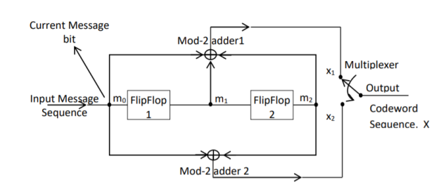
Fig: Convolutional Encoder
In a convolutional code, the encoding operation is the discrete-time convolution of the input data sequence with the impulse response of the encoder. The input message bits are stored in the fixed length shift register and they are combined with the help of mod-2 adders. This operation is equivalent to binary convolution and hence it is called convolutional coding. The figure above shows the connection diagram for an example convolutional encoder.
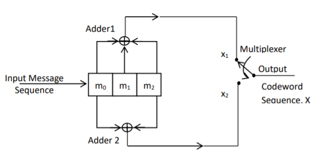
Fig: Convolutional Encoder redrawn alternatively
The encoder of a binary convolution code may be viewed as a finite-state machine. It consists of M-stage shift register with prescribed connections to modulo2 adders. A multiplexer serializes the outputs of the adders. The convolutional codes generated by these encoders of Figure above are non-systematic form. Consider that the current message bit is shifted to position m0. Then m1 and m2 store the previous two message bits. Now, by mod-2 adders 1 and 2 we get the new values of X1 and X2. We can write
X1 = m0 m1 m2 and
X2 = m0 m2
The multiplexer switch first samples X1 and then X2. Then next input bit is taken and stored in m0. The shift register then shifts the bit already in m0 to m1. The bit already in m1 is shifted to m2. The bit already in m2 is discarded. Again, X1 and X2 are generated according to this new combination of m0, m1 and m2. This process is repeated for each input message bit. Thus, the output bit stream for successive input bits will be,
X = x1 x2 x1 x2 x1 x2…….. And so on
In this convolutional encoder, for every input message bit, two encoded output bits X1 and X2 are transmitted. Hence number of message bits, k = 1. The number of encoded output bits for one message bit, n = 2.
Code rate: The code rate of this convolutional encoder is given by
Code rate, r = 𝑀𝑒𝑠𝑠𝑎𝑔𝑒𝑏𝑖𝑡𝑠 (𝑘)/𝑒𝑛𝑐𝑜𝑑𝑒𝑟𝑜𝑢𝑡𝑝𝑢𝑡𝑏𝑖𝑡𝑠 (𝑛) = 𝑘/𝑛 = 1/2 where 0 < r < 1
Constraint Length: The constraint length (K) of a convolution code is defined as the number of shifts over which a single message bit can influence the encoder output. It is expressed in terms of message bits. For the encoder of Figure above, constraint length is K = 3 bits. Because, a single message bit influences encoder output for three successive shifts. At the fourth shift, the message bit is lost and it has no effect on the output. For the encoder of Figure above, whenever a particular message bit enters the shift register, it remains in the shift register for three shifts ie.,
First Shift → Message bit is entered in position m0.
Second Shift → Message bit is shifted in position m1.
Third Shift → Message bit is shifted in position m2.
Constraint length ‘K’ is also equal to one plus the number of shift registers required to implement the encoder.
Dimension of the Code
The code dimension of a convolutional code depends on the number of message bits ‘k’, the number of encoder output bits, ‘n’ and its constraint length ‘K’. The code dimension is therefore represented by (n, k, K). For the encoder shown in figure above, the code dimension is given by (2, 1, 3) where n = 2, k = 1 and constraint length K = 3.
Graphical representation of convolutional codes
Convolutional code structure is generally presented in graphical form by the following three equivalent ways.
1. By means of the state diagram
2. By drawing the code trellis
3. By drawing the code tree
These methods can be better explained by using an example.
For the convolutional encoder given below in Figure, determine the following. a) Code rate b) Constraint length c) Dimension of the code d) Represent the encoder in graphical form.
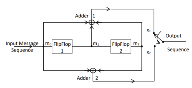
a) Code rate:
The code rate, r = 𝑘/𝑛. The number of message bits, k = 1.
The number of encoder output bits, n = 2.
Hence code rate, r = 1/2
b) Constraint length:
Constraint length, k = 1 + number of shift registers.
Hence k = 1 + 2 = 3
c) Code dimension:
Code dimension = (n, k,K) = (2, 1, 3)
Hence the given encoder is of ½ rate convolutional encoder of dimension (2, 1, 3).
d) Graphical form representation
The encoder output is X = (x1 x2 x1 x2 x1 x2….. And so on)
The Mod-2 adder 1 output is x1 = m0 m1 m2
The Mod-2 adder 2 output is x2 = m0 m2.
We can represent the encoder output for possible input message bits in the form of a Logic table.
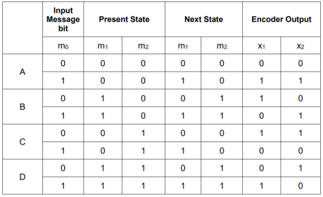
Output x1 = m0 m1 m2 and x2 = m0 m2
- The encoder output depends on the current input message bit and the contents in the shift register ie., the previous two bits.
- The present condition of the previous two bits in the shift register may be in four combinations. Let these combinations 00, 10, 01 and 11 be corresponds to the states A, B, C and D respectively.
- For each input message bit, the present state of the m1 and m2 bits will decide the encoded output.
- The logic table presents the encoded output x1 and x2 for the possible ‘0’ or ‘1’ bit input if the present state is A or B or C or D.
1. State diagram representation
- The state of a convolutional encoder is defined by the contents of the shift register. The number of states is given by 2k-1 = 23-1 = 22 = 4. Here K represents the constraint length.
- Let the four states be A = 00, B = 10, C = 01 and D = 11 as per the logic table. A state diagram as shown in the figure below illustrates the functioning of the encoder.
- Suppose that the contents of the shift register is in the state A = 00. At this state, if the incoming message bit is 0, the encoder output is X = (x1 x2) = 00. Then if the m0, m1 and m2 bits are shifted, the contents of the shift register will also be in state A = 00. This is represented by a solid line path starting from A and ending at A itself.
- At the ‘A’ state, if the incoming message bit is 1, then the encoder output is X = 11. Now if the m0, m1 and m2 bits are shifted, the contents of the shift register will become the state B = 10. This is represented by a dashed line path starting from A and ending at B.
- Similarly, we can draw line paths for all other states, as shown in the Figure below.
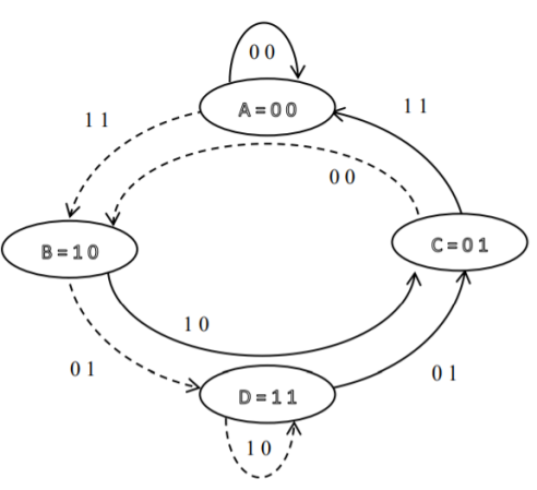
Fig: State Diagram
2. Code tree representation
- The code tree diagram is a simple way of describing the encoding procedure. By traversing the diagram from left to right, each tree branch depicts the encoder output codeword.
- Figure below shows the code representation for this encoder.
- The code tree diagram starts at state A =00. Each state now represents the node of a tree. If the input message bit is m0 = 0 at node A, then path of the tree goes upward towards node A and the encoder output is 00. Otherwise, if the input message bit is m0 = 1, the path of the tree goes down towards node B and the encoder output is 11.
- Similarly depending upon the input message bit, the path of the tree goes upward or downward. On the path between two nodes the outputs are shown.
- In the code tree, the branch pattern begins to repeat after third bit, since particular message bit is stored in the shift registers of the encoder for three shifts.
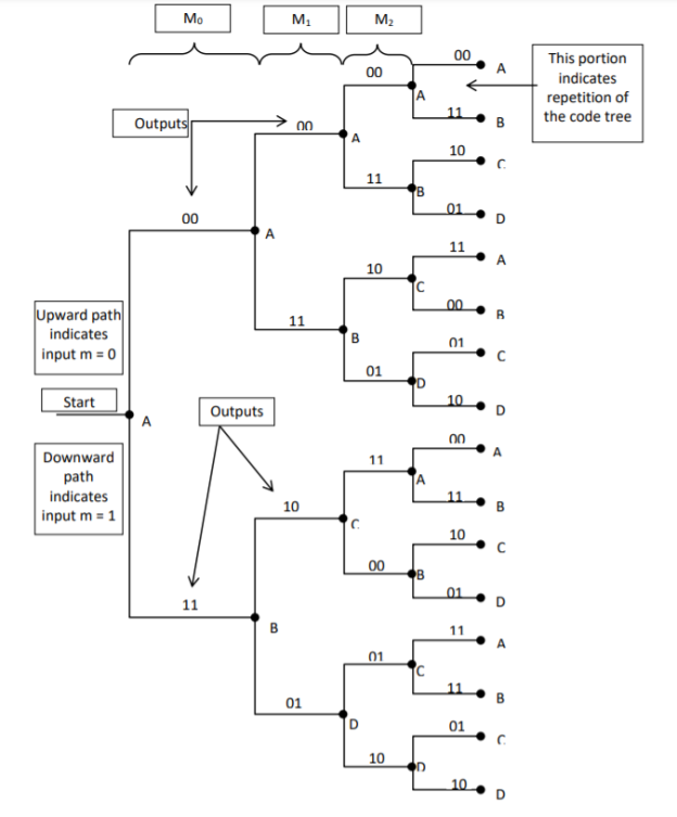
Fig: Code Tree Representation
3. Code trellis representation
- Code trellis is the more compact representation of the code tree. In the code tree there are four states (or nodes). Every state goes to some other state depending upon the input message bit.
- Code trellis represents the single and unique diagram for such steady state transitions. The Figure below shows the code trellis diagram.
- The nodes on the left denote four possible current states and those on the right represents next state. The solid transition line represents for input message m0 = 0 and dashed line represents input message m0 = 1.
- Along with each transition line, the encoder output x1 x2 is represented during that transition.
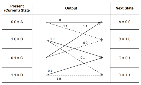
Fig: Code Trellis
Advantages of convolutional codes
- The convolutional codes operate on smaller blocks of data. Hence decoding delay is small.
- The storage hardware required is less.
Disadvantages of convolutional codes
- Due to complexity, the convolutional codes are difficult to analyze.
- These codes are not developed much as compared to block codes.
Key takeaway
Comparison between Linear Block codes and Convolutional codes
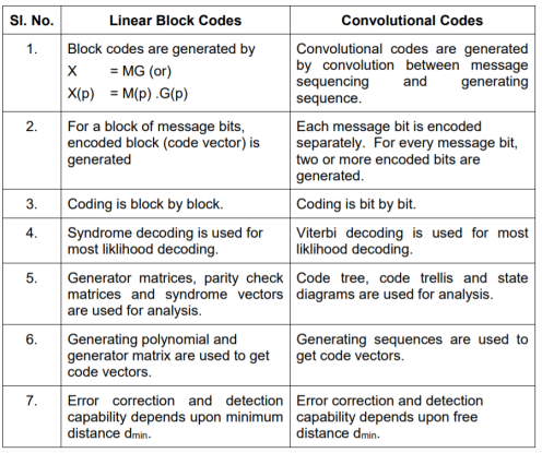
The Viterbi Algorithm (VA) finds a maximum likelihood (ML) estimate of a transmitted code sequence c from the corresponding received sequence r by maximizing the probability p(r|c) that sequence r is received conditioned on the estimated code sequence c. Sequence c must be a valid coded sequence. The Viterbi algorithm utilizes the trellis diagram to compute the path metrics. The channel is assumed to be memory less, i.e. the noise sample affecting a received bit is independent from the noise sample affecting the other bits. The decoding operation starts from state ‘00’, i.e. with the assumption that the initial state of the encoder is ‘00’.
With receipt of one noisy codeword, the decoding operation progresses by one step deeper into the trellis diagram. The branches, associated with a state of the trellis tell us about the corresponding codewords that the encoder may generate starting from this state. Hence, upon receipt of a codeword, it is possible to note the ‘branch metric’ of each branch by determining the Hamming distance of the received codeword from the valid codeword associated with that branch. Path metric of all branches, associated with all the states are calculated similarly.
Now, at each depth of the trellis, each state also carries some ‘accumulated path metric’, which is the addition of metrics of all branches that construct the ‘most likely path’ to that state. As an example, the trellis diagram of the code shown in Fig., has four states and each state has two incoming and two outgoing branches. At any depth of the trellis, each state can be reached through two paths from the previous stage and as per the VA, the path with lower accumulated path metric is chosen. In the process, the ‘accumulated path metric’ is updated by adding the metric of the incoming branch with the ‘accumulated path metric’ of the state from where the branch originated. No decision about a received codeword is taken from such operations and the decoding decision is deliberately delayed to reduce the possibility of erroneous decision. The basic operations which are carried out as per the hard-decision Viterbi Algorithm after receiving one codeword are summarized below:
a) All the branch metrics of all the states are determined;
b) Accumulated metrics of all the paths (two in our example code) leading to a state are calculated taking into consideration the ‘accumulated path metrics’ of the states from where the most recent branches emerged;
c) Only one of the paths, entering into a state, which has minimum ‘accumulated path metric’ is chosen as the ‘survivor path’ for the state (or, equivalently ‘node’);
d) So, at the end of this process, each state has one ‘survivor path’. The ‘history’ of a survivor path is also maintained by the node appropriately ( e.g. By storing the codewords or the information bits which are associated with the branches making the path)
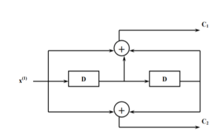
e) Steps a) to d) are repeated and decoding decision is delayed till sufficient number of codewords has been received. Typically, the delay in decision making = Lx k codewords where L is an integer, e.g. 5 or 6. For the code in Fig. Above, the decision delay of 5x3 = 15 codewords may be sufficient for most occasions. This means, we decide about the first received codeword after receiving the 16th codeword. The decision strategy is simple.
Upon receiving the 16th codeword and carrying out steps a) to d), we compare the ‘accumulated path metrics’ of all the states ( four in our example) and chose the state with minimum overall ‘accumulated path metric’ as the ‘winning node’ for the first codeword. Then we trace back the history of the path associated with this winning node to identify the codeword tagged to the first branch of the path and declare this codeword as the most likely transmitted first codeword. The above procedure is repeated for each received codeword hereafter. Thus, the decision for a codeword is delayed but once the decision process starts, we decide once for every received codeword. For most practical applications, including delay-sensitive digital speech coding and transmission, a decision delay of Lx k codewords is acceptable.
Soft-Decision Viterbi Algorithm
In soft-decision decoding, the demodulator does not assign a ‘0’ or a ‘1’ to each received bit but uses multi-bit quantized values. The soft-decision Viterbi algorithm is very similar to its hard-decision algorithm except that squared Euclidean distance is used in the branch metrics instead of simpler Hamming distance. However, the performance of a soft-decision VA is much more impressive compared to its HDD (Hard Decision Decoding) counterpart The computational requirement of a Viterbi decoder grows exponentially as a function of the constraint length and hence it is usually limited in practice to constraint lengths of K = 9.
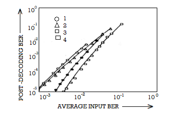
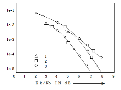
Fano algorithm
Source encoding is a process in which the output of an information source is converted into a r-ary sequence where r is the number of different symbols used in this transformation process. The functional block that performs this task in a communication system is called source encoder.
The input to the encoder is the symbol sequence emitted by the information source and the output of the encoder is r-ary sequence.
If r=2 then it is called the binary sequence
r=3 then it is called ternary sequence
r=4 then it is called quarternary sequence.
Let the source alphabet S consist of “q” number of source symbols given by S = {S1,S2…….Sq} . Let another alphabet X called the code alphabet consists of “r” number of coding symbols given by
X = {X1,X2………………………Xr}
The term coding can now be defined as the transformation of the source symbols into some sequence of symbols from code alphabet X.
Shannon’s encoding algorithm
The following steps indicate the Shannon’s procedure for generating binary codes.
Step 1:
List the source symbols in the order of non-increasing probabilities
S = {S1,S2,S3……………………Sq} with P = {P1,P2,P3…………………..Pq}
P1 ≥P2 ≥P3 ≥………………….Pq
Step 2
Compute the sequences α + 1 = 0
α 2 = P 1= P1 + α 1
α 3= P2 + P1 = P2 + α 2
α 4 = P3+P2+P1 = P3 + α 3
….. ……..
α q+ 1 = Pq + Pq-1 +…………+ P2 + P1 = Pq + α q
Step 3:
Determine the smallest integer value of “li using the inequality
2 li ≥ 1/Pi for all i=1,2,……………………q.
Step 4:
Expand the decimal number αi in binary form upto li places neglecting expansion beyond li places.
Step 5:
Remove the binary point to get the desired code.
Example:
Apply Shannon’s encoding (binary algorithm) to the following set of messages and obtain code efficiency and redundancy.
m 1 | m 2 | m 3 | m 4 | m 5 |
1/8 | 1/16 | 3/16 | ¼ | 3/8 |
Step 1:
The symbols are arranged according to non-increasing probabilities as below:
m 5 | m 4 | m 3 | m 2 | m 1 |
3/8 | ¼ | 3/16 | 1/16 | 1/8 |
P 1 | P 2 | P 3 | P 4 | P 5 |
Step 2:
The following sequences of α are computed
α 1 = 0
α 2 = P1 + α 1 = 3/8 + 0 = 0.375
α 3 = P2 + α 2 = ¼ + 0.375 = 0.625
α 4 = P3 + α 3 = 3/16 + 0.625 = 0.8125
α 5 = P4 + α 4 = 1/16 + 0.8125 = 0.9375
α 6 = P5 + α 5 = 1/8 + 0.9375 = 1
Step 3:
The smallest integer value of li is found by using
2 li ≥ 1/Pi
For i=1
2 l1 ≥ 1/P1
2 l1 ≥ 1/3/8 = 8/3 = 2.66
The smallest value ofl1 which satisfies the above inequality is 2 therefore l1 = 2.
For i=2 2l2 ≥ 1/P2 Therefore 2 l2 ≥ 1/P2
2 l2 ≥ 4 therefore l2 = 2
For i =3 2 l3 ≥ 1/P3 Therefore 2 l3 ≥ 1/P3 2 l3 ≥ 1/ 3/16 = 16/3 l3 =3
For i=4 2l4 ≥ 1/P4 Therefore 2 l4 ≥ 1/P4
2 l4 ≥ 8 Therefore l4 = 3
For i=5
2 l5 ≥ 1/P5 Therefore
2 l5 ≥ 16 Therefore l5=4
Step 4:
The decimal numbers αi are expanded in binary form upto li places as given below.
α 1 = 0
α 2 = 0.375
0.375 x2 = 0.750 with carry 0
0.75 x 2 = 0.50 with carry 1
0.50 x 2 = 0.0 with carry 1
Therefore
(0.375) 10 = (0.11)2
α 3 = 0.625
0.625 X 2 = 0.25 with carry 1
0.25 X 2 = 0.5 with carry 0
0.5 x 2 = 0.0 with carry 1
(0.625) 10 = (0.101)2
α 4 = 0.8125
0.8125 x 2 = 0.625 with carry 1
0.625 x 2 = 0.25 with carry 1
0.25 x 2 = 0. 5 with carry 0
0.5 x 2 = 0.0 with carry 1
(0.8125) 10 = (0.1101)2
α 5 = 0.9375
0.9375 x 2 = 0.875 with carry 1
0.875 x 2 = 0.75 with carry 1
0.75 x 2 = 0.5 with carry 1
0.5 x 2 = 0.0 with carry 1
(0.9375) 10 = (0.1111)2
α 6 = 1
Step 5:
α 1 = 0 and l1 = 2 code for S1 ----00
α 2 =(0.011) 2 and l2 =2 code for S2 ---- 01
α 3 = (.101)2 and l3 =3 code for S3 ------- 101
α 4 = (.1101)2 and l4 =3 code for S ----- 110
α 5 = (0.1111)2 and l5 = 4 code for s5 --- 1111
The average length is computed by using
L = 
= 3/8 x 2 + ¼ x 2 + 3/16 x 3 + 1/8 x 3 + 1/16 x 4
L= 2.4375 bits/msg symbol
The entropy is given by
H(s) = 3/8 log (8/3) + ¼ log 4 + 3/16 log 16/3 + 1/8 log 8 + 1/16 log 16
H(s) =2.1085 bits/msg symbol.
Code efficiency is given by
c = H(s)/L = 2.1085/2.4375 = 0.865
Percentage code efficiency = 86.5% c
Code redundancy
R c = 1 - c = 0.135 or 13.5%.
References:
1. Lathi B.P. - Modern Digital and Analog communications systems - PRISM Indian Ed.
2. Digital Communication: J.S.Chitode
3. Digital Communication (Fundamentals & applications): Bernard Scalr
4. Introduction to Error Control Codes: Salvatore Gravano
5. OFDM For wireless communication systems: Ramjee Prasad
6. Modern Communication systems (Principles and application): Leon W. Couch II (PHI)
7. Error Control Coding: Shu Lin & Daniel J.Costello