Unit - 6
Spread - Spectrum methods
- Pseudo-Noise (PN) also known Pseudo Random Binary Sequence (PRBS).
- A Pseudo-Noise code (PN-code) or Pseudo Random Noise Code (PRN code) is a spectrum which generated deterministically by random sequence.
- PN sequence is random occurance of 0’s and 1’s bit stream.
- Directly sequence spread spectrum (DS-SS) system is most popular sequence in DS-SS system bits of PN sequence is known as chips and inverse of its period is known as chip rate.
In frequency hopping spread spectrum (FH-SS) sequence, channel number are pseudo random sequences and hop rate are inverse of its period.
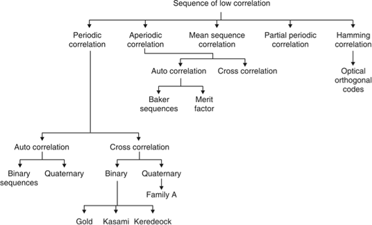
Fig. 1: Overview of PN sequence
Properties
(i) Balance property:
Total no. Of 1’s is more than no. Of 0’s in maximum length sequence.
(ii) Run property 1’s and 0’s stream shows length sequence, every fraction relate some meaning.
Rum | Length |
1/2 | 1 |
1/4 | 2 |
1/8 | 3 |
(iii) Correlation property:
If compared sequences are found similar then it is auto correlation.
If compared sequences are found mismatched then it is cross correlation.
Let (K) and y (K) are two sequences then correlation R (m) will be:

Correlation R (m) in pattern of digital bit sequence will be:

y1 = P1 q1
y1 = 0 if P1 q1
y1 = 1 if P1 = q1
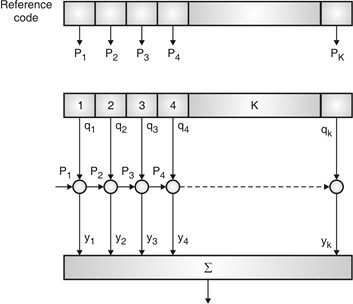
Fig. 2: Correlator
Fig. Shows Pi is a sequence which shifts through K bit shift register. K is length of correlate. Output achieved by K XNOR gate after comparison.
(iv) Shift and add:
By using X-OR gate, shift sequence modulo-2 added to upshifted sequence.
PN sequence generation methodologies:
(i) Using shift register with feedback.
(ii) Series parallel method for high speed PN generation.
(iii) Avoiding zero state.
(iv) Barker sequence.
(v) Kasami sequence.
(vi) Gold sequence.
Direct Sequence Spread Spectrum (DSSS) using BPSK modulation, so the first reversing switch introduces 180 degree phase reversals according to a pseudo-random code, while the second introduces the same reversals to reconstitute the original, narrow-band signal. The output is a “recompressed” narrow-band signal.
DSSS is a spread spectrum modulation technique used for digital signal transmission over airwaves. It was originally developed for military use, and employed difficult-to-detect wideband signals to resist jamming attempts.
It is also being developed for commercial purposes in local and wireless networks.
The stream of information in DSSS is divided into small pieces, each associated with a frequency channel across spectrums. Data signals at transmission points are combined with a higher data rate bit sequence, which divides data based on a spreading ratio. The chipping code in a DSSS is a redundant bit pattern associated with each bit transmitted.
This helps to increase the signal's resistance to interference. If any bits are damaged during transmission, the original data can be recovered due to the redundancy of transmission.
The entire process is performed by multiplying a radio frequency carrier and a pseudo-noise (PN) digital signal. The PN code is modulated onto an information signal using several modulation techniques such as quadrature phase-shift keying (QPSK), binary phase-shift keying (BPSK), etc. A doubly-balanced mixer then multiplies the PN modulated information signal and the RF carrier. Thus, the TF signal is replaced with a bandwidth signal that has a spectral equivalent of the noise signal. The demodulation process mixes or multiplies the PN modulated carrier wave with the incoming RF signal. The result produced is a signal with a maximum value when two signals are correlated. Such a signal is then sent to a BPSK demodulator. Although these signals appear to be noisy in the frequency domain, bandwidth provided by the PN code permits the signal power to drop below the noise threshold without any loss of information.
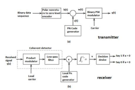
Fig 3(a) Transmitter (b) Receiver of DS-SS Technique
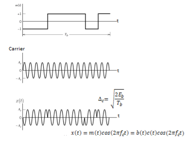
Fig 4 Wave forms for DSSS
Key takeaway
- In practice, the transmitter and receiver of Figures shown above are followed. In the transmitter spectrum spreading is performed prior to phase modulation. Also phase demodulation is done first and then despreading is done second, in the receiver.
- In the model of DS spread spectrum BPSK system used for analysis, the order of these two operations is interchanged. In the transmitter, BPSK is done first and spectrum spreading is done subsequently. Similarly, at the receiver also, spectrum de spreading is done first and then phase demodulation is done second.
- This is possible, because the spectrum spreading and BPSK are both linear operations.

Fig. 5: General spread spectrum structure
- Spread spectrum is specially used for wireless communication signal spreading. Transmitted signals frequency varies deliberately.
- Frequency hopping and direct sequence are two popular spread spectrums.
- In frequency hopping, signals are broadcast over any random series of frequency while in direct sequence each bit is in order of multiple bit of transmitting signal it uses chipping code.
Frequency Hoping Spread Spectrum (FHSS)
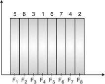
Fig. 6: Channel assignment
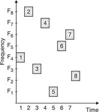
Fig. 7: Channel use
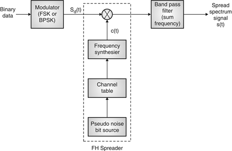
Fig. 8: FHSS (Transmitter)
In FHSS, according to PN sequence RF carries frequency used to get change.
FHSS has two types
1. Fast hopped FHSS.
2. Slow hopped FHSS.
Hopping is done with faster rate compared to bit rate in fast hopped FHSS while slow rate compared to message bit rate in slow hopped FHSS.
FHSS systems rely on changes in RF carrier frequencies which turn into burst errors.
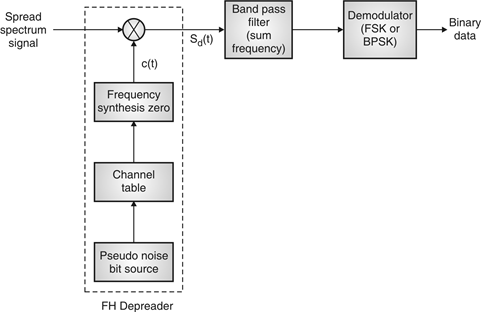
Fig. 9: FHSS (Receiver)
Performance
Sr. No. | Parameter | Slow frequency hopping | Fast frequency hopping |
1 | Definition | Multiple symbols are transmitted in one frequency hop. | Multiple hops are taken to transmit one symbol. |
2 | Chip rate | Symbol rate is equal to chip rate. | Hop rate is equal to chip rate. |
3 |   | Hop rate is lower than symbol rate. | Hop rate is higher than symbol rate. |
4 | Carrier frequencies | One or more symbols are transmitted over the same carrier frequency. | One symbol is transmitted over multiple carriers in different hops. |
5 | Jammer interference | This signal can be detected by jammer if carrier frequency in one hop is known. | This signal is difficult to detect since one symbol is transmitted on multiple carrier frequencies. |
Synchronization is the process of ensuring that the locally produced carrier at the receiver is in frequency and phase synchronism with the carrier at the transmitter. For successful functioning in spread spectrum communication systems, the transmitted and received PN codes must be perfectly matched.
(i) Both the carrier frequency and the PN clock can drift with time.
(ii) If the transmitter and receiver are moving relative to one other, as in mobile and satellite spread spectrum systems, the carrier and PN clocks will experience Doppler frequency shift.
As a result, the receiver's PN sequence must be synchronized with the transmitter's.
Synchronization steps:
The synchronization of the locally generated spreading signal with the incoming spread spectrum signal normally takes two phases. They are:
1) Acquisition: Bringing the two spreading signals into coarse alignment with one another implies the acquisition stage.
2) Tracking: After acquiring the received spread-spectrum signal, the second phase, tracking, is used to fine-tune the alignment.
The feedback loop is used in both acquisition and tracking.
Acquisition:
There are three types of acquisition schemes. They are
1) Serial search acquisition
2) Parallel search acquisition
3) Sequential search acquisition
1. Serial search acquisition:
A) DS Spread spectrum systems:
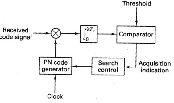
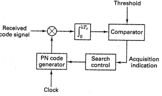
In Direct Sequence spread spectrum systems, the serial search scheme is shown in Figure.
Between the transmitter and the receiver, there is always some initial timing ambiguity. Assume the transmitter contains N chips and each chip has a Tc duration. It's important to linger for Td=NTc to verify synchronism at each time instant if initial synchronization is to take place in the face of additive noise and other interference. In(coarse) time steps of 1/2 Tc, we search throughout the time uncertainty interval.
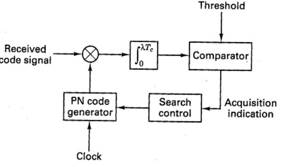
The incoming PN signal and the locally produced PN signal are linked. The output signal is compared to a predefined threshold at specified search intervals of NTc (search dwell time). The locally produced code signal is advanced in time by 1/2Tc seconds if the output is less than the threshold. The procedure of correlation is carried out once more. These actions continue until a signal is detected or a threshold is reached. After then, it's presumed that the PN code was obtained.
As a result, assuming the initial misalignment between the two codes was n chips, the entire acquisition time is equal to
Tacq = 2nNTc seconds
B) FH spread spectrum systems
The serial search strategy for frequency hopping spread spectrum systems is shown in Figure.
A mixer is followed by a bandpass filter (BPF) and a square-law envelope detector in this non-coherent matched filter. The frequency hopper is controlled by the PN code generator. When the local hopping matches that of the received signal, the acquisition is finished.
Let fi be the frequency of the transmitter's frequency synthesizer. Assume that fj is the frequency of the signal generated by the frequency synthesizer in the receiver's acquisition circuit. If fi ≠ fj, the output of BPF will only create a little voltage less than the threshold. If fi = fj at a later time during the search, a huge voltage above the threshold will be created at the BPF output. This means that local hopping is matched with the received signal.
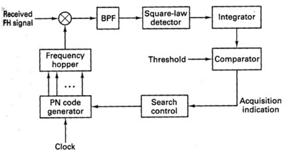
Figure 10. Frequency hopping serial search acquisition
2. Parallel search acquisition
By running two or more correlators in parallel, the parallel search acquisition approach adds a level of parallelism to the process. They'll look for periods that don't overlap. The search time is lowered with this system, but the implementation is more complex and costly.
3. Sequential search acquisition
The dwell time at each delay in the search process is made variable using a correlator with a variable integration period whose (biased) output is compared to two thresholds in this method. As a result, the sequential search strategy produces a more efficient search by reducing the average search time.
Tracking
The initial search process is halted after the signal has been acquired, and fine synchronization and tracking may start. The PN code generator at the receiver is kept in sync with the incoming signal thanks to the tracking. Fine chip synchronization and carrier phase tracking are both included in tracking for coherent demodulation.
A) DS Spread spectrum system:
The Delay-locked loop (DLL) is a common tracking loop for a Direct sequence spectrum signal, as shown in Figure.
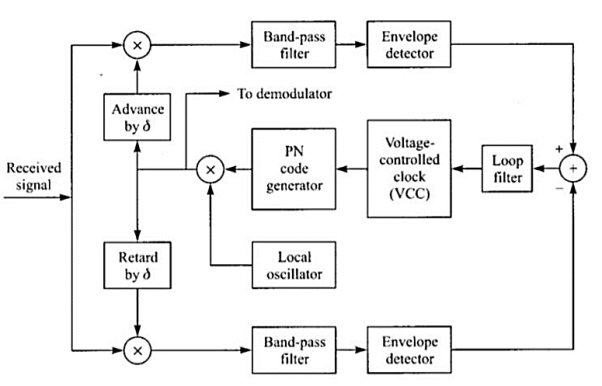
Figure 11: Delay-Locked Loop (DLL) for PN code tracking
The received DS spread spectrum signal is applied to two multipliers at the same time. The PN code for one of the multipliers is delayed by a fraction of the chip interval (δ). The identical PN code is sent to the other multiplier, but it is advanced by δ. Each multiplier's output is sent into a BPF centered on f0.
Each BPF's output is envelope detected and then subtracted. The loop filter, that drives the voltage-controlled oscillator receives this difference signal. The PN code generator uses the VCO as a clock. If the synchronization isn't perfect, one correlator's filtered output will surpass the other. As a result, the VCO will be advanced or postponed properly. The two filtered correlator outputs will be equally displaced from the peak value at the equilibrium point. The output of the PN code generator will then be perfectly synchronized with the received signal supplied into the demodulator.
B) FH Spread spectrum system:
Figure shows a common tracking method for FH spread spectrum communications.
The received signal and the receiver clock have a minor timing error, despite the initial acquisition is successful. The bandwidth of the BPF is on the order of 1/Tc, where Tc is the chip interval, and it is tuned to a single intermediate frequency. Its output is envelope detected before being multiplied by the clock signal to provide a three-level signal. The loop filter is activated by this.

Figure 12: Tracking loop for FH signals
Assume that the chip transitions from the locally generated sinusoidal waveform do not coincide with the incoming signal transitions. The loop filter's output will thus be either positive or negative, depending on whether the VCO is trailing or ahead of the input signal's time. The control signal for changing the VCO timing signal to drive the frequency synthesizer output to appropriate synchronization with the received signal will come from the error signal from the loop filter.
a) Reduced interference: In SS systems, interference from undesired sources is considerably reduced due to the processing gain of the system.
b) Low susceptibility to multi-path fading: Because of its inherent frequency diversity properties, a spread spectrum system offers resistance to degradation in signal quality due to multi-path fading. This is particularly beneficial for designing mobile communication systems.
c) Co-existence of multiple systems: With proper design of pseudo-random sequences, multiple spread spectrum systems can co-exist.
d) Immunity to jamming: An important feature of spread spectrum is its ability to withstand strong interference, sometimes generated by an enemy to block the communication link. This is one reason for extensive use of the concepts of spectrum spreading in military communications.
A specific example of the use of spread spectrum technology is the North American Code Division Multiple Access (CDMA) Digital Cellular (IS-95) standard. The CDMA employed in this standard uses a spread spectrum signal with 1.23-MHz spreading bandwidth. Since in a CDMA system every user is a source of interference to other users, control of the transmitted power has to be employed (due to near-far problem). Such control is provided by sophisticated algorithms built into control stations.
The standard also recommends use of forward error-correction coding with interleaving, speech activity detection and variable-rate speech encoding. Walsh code is used to provide 64 orthogonal sequences, giving rise to a set of 64 orthogonal ‘code channels’. The spread signal is sent over the air interface with QPSK modulation with Root Raised Cosine (RRC) pulse shaping. Other examples of using spread spectrum technology in commercial applications include satellite communications, wireless LANs based on IEEE 802.11 standard etc.
Satellite systems, mobile networks
Satellites are used to transfer information from one place to another using communication satellite on Earth’s orbit. Satellite communication began in 1957 and the first artificial satellite launched was Sputnik I by the USSR. The satellite communication can be one way as well. In this case the transmission of signal from the transmitter of first earth satellite and the receiver of the second earth satellite is in one direction.
In two-way communication the information is exchanged between the two earth stations. There are two uplinks and two downlinks required to achieve two ways communication.
The main elements of communication satellite are
a) Uplink
b) Transponders
c) Downlink
The block diagram of satellite communication is shown below. A communication satellite is basically a R.F repeater.
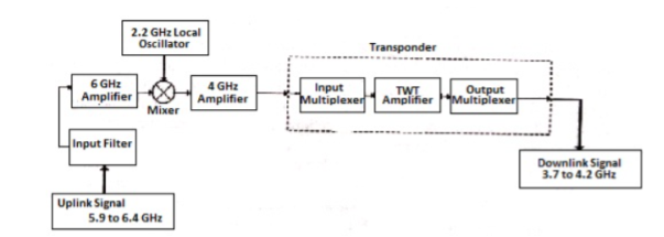
Fig 13. Block Diagram of Satellite Communication
The uplink frequencies used are of range 5.9GHz-6.4GHz these frequencies are converted to lower frequencies and amplified. The mixers and local oscillators are used to convert the higher frequency uplink signals to lower frequency signals. The com satellite receives this signal amplifies it and then transmits it so that there is no interference in the uplink and down link signals.
The transponders provide the medium for two-way communication. The downlink frequency used for transmission is from the range of 3.7GHz to 4.2GHz. The number of transponders per satellite depends upon the task which the satellite needs to do. For television broadcast two transponders are used in a satellite.
Advantages
The advantages of satellite communication are
- They are easy to install.
- The communication can be set up in every part of earth with the help of satellites.
- The network is controlled by the user.
- The elasticity of these circuits is excellent
Applications
The applications of satellite communication are
- Telephone
- Television
- Digital cinema
- Radio broadcasting
- Amateur radio
- Internet access
- Military
- Disaster Management
Wireless LAN IEEE 802.11
IEEE 802.11 is a set of standards carrying out wireless local area network (WLAN) computer communication in the 2.4, 3.6 and 5 GHz frequency bands. They are created and maintained by the IEEE LAN/MAN Standards Committee (IEEE 802)
802.11a — an extension to 802.11 that applies to wireless LANs and provides up to 54-Mbps in the 5GHz band. 802.11a uses an orthogonal frequency division multiplexing encoding scheme rather than FHSS or DSSS.
802.11b — an extension to 802.11 that applies to wireless LANS and provides 11 Mbps transmission in the 2.4 GHz band. 802.11b uses only DSSS. 802.11b was a 1999 ratification to the original 802.11 standard, allowing wireless functionality comparable to Ethernet.
802.11e — a wireless draft standard that defines the Quality of Service support for LANs, and is an enhancement to the 802.11a and 802.11b wireless LAN (WLAN) specifications. 802.11e adds QoS features and multimedia support to the existing IEEE 802.11b and IEEE 802.11a wireless standards, while maintaining full backward compatibility with these standards.
802.11g — applies to wireless LANs and is used for transmission over short distances at up to 54-Mbps in the 2.4 GHz bands.
802.11n — 802.11n builds upon previous 802.11 standards by adding multiple-input multiple-output. The additional transmitter and receiver antennas allow for increased data throughput through spatial multiplexing and increased range by exploiting the spatial diversity through coding schemes like Alamouti coding. The real speed would be 100 Mbit/s (even 250 Mbit/s in PHY level), and so up to 4-5 times faster than 802.11g.
- CDMA stands for Code Division Multiple Access. CDMA is a technique for spread spectrum multiple access.
- Data signals are XOReD with pseudorandom code and then transmitted over a channel.
- Different codes are used to modulate their signals, selection of code to modulate is important aspect as it relates with performance of system.
- In CDMA, single channel uses entire bandwidth and it does not share time as all stations transmit data simultaneously. Due to this CDMA differ from FDMA and TDMA.
- Let us assume we have 4 different stations A, B, C and D. All 4 stations connected to same channel. Data from station A is d1, B is d2, C is d3 and D is d4 similarly code assigned to A is C1, B is C2, C is C3 and D is C4.
- To transmit data, all 4 stations have multiplication strategy i.e. either code multiply by itself. It results in 4 stations or code multiply results in 4 stations or code multiply results in 4 station of code multiply by another, it results in zero station.
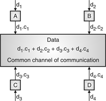
Fig. 14: Communication of station with code
- If station C and station D are talking to each other, D wants to listen whatever C is saying. It multiplies data on channel by C3 of station C.
- As C3 C3 is 4 and rest of combination i.e. C1 C3, C2 C3 and C4 C3 are all zero.
- Every station has some code, which is sequence of numbers known as chips.
- Sequence should be selected in proper manner to get appropriate codes. Orthogonal sequence has some properties:
- Multiplication of sequence by a scalar.
- Inner product of two equal sequences.
- Inner product of two different sequences.
- Sequence generation uses Walsh table to generate chip sequence.
- CDMA systems spread symbols. Before spreading symbols it uses distinctive code before transmission.
- On receiver side all symbols accepted by dispreading with help of correlating symbols. A signal which does not required are neither correlate nor de-spread to accept.
- CDMA signals are sequence of 0’s and 1’s and sequences are generated from code. Symbol per second means original data rate and chip rates means code chipping rate.
- Every code belongs to distinct set of data.
- CDMA allows space, time frequency signals transmission. Different coding method used in CDMA are:
(a) Autocorrelation codes
(i) Barker code.
(ii) Pseudo-noise code.
(b) Other important codes
(i) Orthogonal codes.
(ii) Walsh codes.
(iii) Scrambling codes.
(iv) Channelization codes.
(v) Carrier modulation codes.
- The Orthogonal Frequency Division Multiplexing (OFDM) transmission scheme is the optimum version of the multicarrier transmission scheme. In the past, as well as in the present, the OFDM is referred in the literature Multi-carrier, Multi-tone and Fourier Transform.
- In mid-1960 parallel data transmission and frequency multiplexing came. In high-speed digital communication OFMD is employed. OFMD has a drawback of massive complex computation and high-speed memory which are no more problems now due to introduction of DSP and VLSI.
- The implementation of this technology is cost effective as FFT eliminates array of sinusoidal generators and coherent demodulation required in parallel data systems· The data to be transmitted is spread over large number of carriers. Each of them is then modulated at low rates. By choosing proper frequency between them the carriers are made orthogonal to each other.
- In OFDM the spectral overlapping among the sun carrier is allowed, at the receiver due to orthogonality the subcarriers can be separated. This provides better spectral efficiency and use to steep BPF is eliminated.
- The problems arising in single carrier scheme are eliminated in OFDM transmission system. It has the advantage of spreading out a frequency selective fade over many symbols. This effectively randomizes burst errors caused by fading or impulse interference so that instead of several adjacent symbols being completely destroyed, many symbols are only slightly distorted.
- Because of this reconstruction of majority of them even without forward error correction is possible. As the entire bandwidth is divided into many narrow bandwidths, the sub and become smaller than the coherent bandwidth of the channel which makes the frequency response over individual sub bands is relatively flat. Hence, equalization becomes much easier than in single carrier system and it can be avoided altogether if differential encoding is employed.
- The orthogonality of sub channels in OFDM can be maintained and individual subchannels can be completely separated by the FFT at the receiver when there are no inter symbol interference (ISI) and intercarrier interference (ICI) introduced by the transmission channel distortion.
- Since the spectra of an OFDM signal is not strictly band limited, linear distortions such as multipath propagation causes each subchannel to spread energy into the adjacent channels and consequently cause ISI.
- One way to prevent ISI is to create a cyclically extended guard interval, where each OFDM symbol is preceded by a periodic extension of the signal itself. When the guard interval is longer than the channel impulse response or multipath delay, the ISI can be eliminated.
- By using time and frequency diversity, OFDM provides a means to transmit data in a frequency selective channel. However, it does not suppress fading itself. Depending on their position in the frequency domain, individual subchannels could be affected by fading.
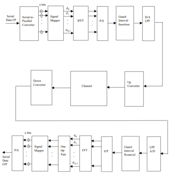
Fig 15: General OFDM System
The incoming signal is converted to parallel form by serial to parallel converter. After that it is grouped in x bits to form a complex number. These numbers are then modulated in a baseband manner by IFFT. Then through parallel to serial converted they are converted to serial data and transmitted. In order to avoid inter symbol interference a guard interval is inserted between the symbols. The discrete symbols are converted to analog and lowpass filtered for RF up-conversion. The receiver performs the inverse process of the transmitter. One tap equalizer is used to correct channel distortion. The tap coefficients of the filter are calculated based on channel information.
Key takeaway
The OFDM scheme differs from traditional FDM in the following interrelated ways:
- Multiple carriers (called subcarriers) carry the information stream
- The subcarriers are orthogonal to each other.
- A guard interval is added to each symbol to minimize the channel delay spread and inter-symbol interference.
References:
1. Lathi B.P. - Modern Digital and Analog communications systems - PRISM Indian Ed.
2. Digital Communication: J.S.Chitode
3. Digital Communication (Fundamentals & applications): Bernard Scalr
4. Introduction to Error Control Codes: Salvatore Gravano
5. OFDM For wireless communication systems: Ramjee Prasad
6. Modern Communication systems (Principles and application): Leon W. Couch II (PHI)
7. Error Control Coding: Shu Lin & Daniel J.Costello
Unit - 6
Spread - Spectrum methods
Unit - 6
Spread - Spectrum methods
- Pseudo-Noise (PN) also known Pseudo Random Binary Sequence (PRBS).
- A Pseudo-Noise code (PN-code) or Pseudo Random Noise Code (PRN code) is a spectrum which generated deterministically by random sequence.
- PN sequence is random occurance of 0’s and 1’s bit stream.
- Directly sequence spread spectrum (DS-SS) system is most popular sequence in DS-SS system bits of PN sequence is known as chips and inverse of its period is known as chip rate.
In frequency hopping spread spectrum (FH-SS) sequence, channel number are pseudo random sequences and hop rate are inverse of its period.
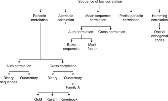
Fig. 1: Overview of PN sequence
Properties
(i) Balance property:
Total no. Of 1’s is more than no. Of 0’s in maximum length sequence.
(ii) Run property 1’s and 0’s stream shows length sequence, every fraction relate some meaning.
Rum | Length |
1/2 | 1 |
1/4 | 2 |
1/8 | 3 |
(iii) Correlation property:
If compared sequences are found similar then it is auto correlation.
If compared sequences are found mismatched then it is cross correlation.
Let (K) and y (K) are two sequences then correlation R (m) will be:

Correlation R (m) in pattern of digital bit sequence will be:

y1 = P1 q1
y1 = 0 if P1 q1
y1 = 1 if P1 = q1
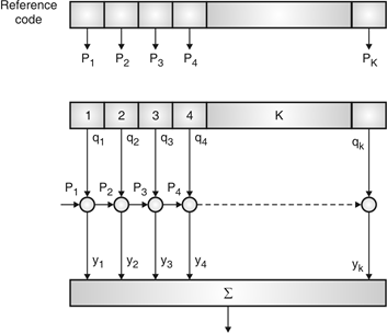
Fig. 2: Correlator
Fig. Shows Pi is a sequence which shifts through K bit shift register. K is length of correlate. Output achieved by K XNOR gate after comparison.
(iv) Shift and add:
By using X-OR gate, shift sequence modulo-2 added to upshifted sequence.
PN sequence generation methodologies:
(i) Using shift register with feedback.
(ii) Series parallel method for high speed PN generation.
(iii) Avoiding zero state.
(iv) Barker sequence.
(v) Kasami sequence.
(vi) Gold sequence.
Direct Sequence Spread Spectrum (DSSS) using BPSK modulation, so the first reversing switch introduces 180 degree phase reversals according to a pseudo-random code, while the second introduces the same reversals to reconstitute the original, narrow-band signal. The output is a “recompressed” narrow-band signal.
DSSS is a spread spectrum modulation technique used for digital signal transmission over airwaves. It was originally developed for military use, and employed difficult-to-detect wideband signals to resist jamming attempts.
It is also being developed for commercial purposes in local and wireless networks.
The stream of information in DSSS is divided into small pieces, each associated with a frequency channel across spectrums. Data signals at transmission points are combined with a higher data rate bit sequence, which divides data based on a spreading ratio. The chipping code in a DSSS is a redundant bit pattern associated with each bit transmitted.
This helps to increase the signal's resistance to interference. If any bits are damaged during transmission, the original data can be recovered due to the redundancy of transmission.
The entire process is performed by multiplying a radio frequency carrier and a pseudo-noise (PN) digital signal. The PN code is modulated onto an information signal using several modulation techniques such as quadrature phase-shift keying (QPSK), binary phase-shift keying (BPSK), etc. A doubly-balanced mixer then multiplies the PN modulated information signal and the RF carrier. Thus, the TF signal is replaced with a bandwidth signal that has a spectral equivalent of the noise signal. The demodulation process mixes or multiplies the PN modulated carrier wave with the incoming RF signal. The result produced is a signal with a maximum value when two signals are correlated. Such a signal is then sent to a BPSK demodulator. Although these signals appear to be noisy in the frequency domain, bandwidth provided by the PN code permits the signal power to drop below the noise threshold without any loss of information.
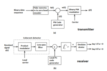
Fig 3(a) Transmitter (b) Receiver of DS-SS Technique
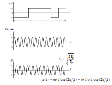
Fig 4 Wave forms for DSSS
Key takeaway
- In practice, the transmitter and receiver of Figures shown above are followed. In the transmitter spectrum spreading is performed prior to phase modulation. Also phase demodulation is done first and then despreading is done second, in the receiver.
- In the model of DS spread spectrum BPSK system used for analysis, the order of these two operations is interchanged. In the transmitter, BPSK is done first and spectrum spreading is done subsequently. Similarly, at the receiver also, spectrum de spreading is done first and then phase demodulation is done second.
- This is possible, because the spectrum spreading and BPSK are both linear operations.

Fig. 5: General spread spectrum structure
- Spread spectrum is specially used for wireless communication signal spreading. Transmitted signals frequency varies deliberately.
- Frequency hopping and direct sequence are two popular spread spectrums.
- In frequency hopping, signals are broadcast over any random series of frequency while in direct sequence each bit is in order of multiple bit of transmitting signal it uses chipping code.
Frequency Hoping Spread Spectrum (FHSS)
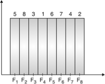
Fig. 6: Channel assignment
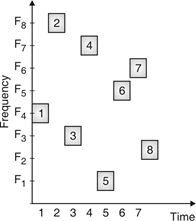
Fig. 7: Channel use
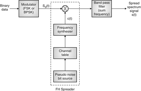
Fig. 8: FHSS (Transmitter)
In FHSS, according to PN sequence RF carries frequency used to get change.
FHSS has two types
1. Fast hopped FHSS.
2. Slow hopped FHSS.
Hopping is done with faster rate compared to bit rate in fast hopped FHSS while slow rate compared to message bit rate in slow hopped FHSS.
FHSS systems rely on changes in RF carrier frequencies which turn into burst errors.
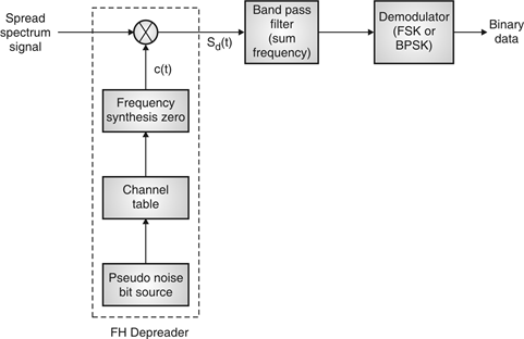
Fig. 9: FHSS (Receiver)
Performance
Sr. No. | Parameter | Slow frequency hopping | Fast frequency hopping |
1 | Definition | Multiple symbols are transmitted in one frequency hop. | Multiple hops are taken to transmit one symbol. |
2 | Chip rate | Symbol rate is equal to chip rate. | Hop rate is equal to chip rate. |
3 |   | Hop rate is lower than symbol rate. | Hop rate is higher than symbol rate. |
4 | Carrier frequencies | One or more symbols are transmitted over the same carrier frequency. | One symbol is transmitted over multiple carriers in different hops. |
5 | Jammer interference | This signal can be detected by jammer if carrier frequency in one hop is known. | This signal is difficult to detect since one symbol is transmitted on multiple carrier frequencies. |
Synchronization is the process of ensuring that the locally produced carrier at the receiver is in frequency and phase synchronism with the carrier at the transmitter. For successful functioning in spread spectrum communication systems, the transmitted and received PN codes must be perfectly matched.
(i) Both the carrier frequency and the PN clock can drift with time.
(ii) If the transmitter and receiver are moving relative to one other, as in mobile and satellite spread spectrum systems, the carrier and PN clocks will experience Doppler frequency shift.
As a result, the receiver's PN sequence must be synchronized with the transmitter's.
Synchronization steps:
The synchronization of the locally generated spreading signal with the incoming spread spectrum signal normally takes two phases. They are:
1) Acquisition: Bringing the two spreading signals into coarse alignment with one another implies the acquisition stage.
2) Tracking: After acquiring the received spread-spectrum signal, the second phase, tracking, is used to fine-tune the alignment.
The feedback loop is used in both acquisition and tracking.
Acquisition:
There are three types of acquisition schemes. They are
1) Serial search acquisition
2) Parallel search acquisition
3) Sequential search acquisition
1. Serial search acquisition:
A) DS Spread spectrum systems:
In Direct Sequence spread spectrum systems, the serial search scheme is shown in Figure.
Between the transmitter and the receiver, there is always some initial timing ambiguity. Assume the transmitter contains N chips and each chip has a Tc duration. It's important to linger for Td=NTc to verify synchronism at each time instant if initial synchronization is to take place in the face of additive noise and other interference. In(coarse) time steps of 1/2 Tc, we search throughout the time uncertainty interval.
The incoming PN signal and the locally produced PN signal are linked. The output signal is compared to a predefined threshold at specified search intervals of NTc (search dwell time). The locally produced code signal is advanced in time by 1/2Tc seconds if the output is less than the threshold. The procedure of correlation is carried out once more. These actions continue until a signal is detected or a threshold is reached. After then, it's presumed that the PN code was obtained.
As a result, assuming the initial misalignment between the two codes was n chips, the entire acquisition time is equal to
Tacq = 2nNTc seconds
B) FH spread spectrum systems
The serial search strategy for frequency hopping spread spectrum systems is shown in Figure.
A mixer is followed by a bandpass filter (BPF) and a square-law envelope detector in this non-coherent matched filter. The frequency hopper is controlled by the PN code generator. When the local hopping matches that of the received signal, the acquisition is finished.
Let fi be the frequency of the transmitter's frequency synthesizer. Assume that fj is the frequency of the signal generated by the frequency synthesizer in the receiver's acquisition circuit. If fi ≠ fj, the output of BPF will only create a little voltage less than the threshold. If fi = fj at a later time during the search, a huge voltage above the threshold will be created at the BPF output. This means that local hopping is matched with the received signal.
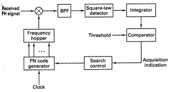
Figure 10. Frequency hopping serial search acquisition
2. Parallel search acquisition
By running two or more correlators in parallel, the parallel search acquisition approach adds a level of parallelism to the process. They'll look for periods that don't overlap. The search time is lowered with this system, but the implementation is more complex and costly.
3. Sequential search acquisition
The dwell time at each delay in the search process is made variable using a correlator with a variable integration period whose (biased) output is compared to two thresholds in this method. As a result, the sequential search strategy produces a more efficient search by reducing the average search time.
Tracking
The initial search process is halted after the signal has been acquired, and fine synchronization and tracking may start. The PN code generator at the receiver is kept in sync with the incoming signal thanks to the tracking. Fine chip synchronization and carrier phase tracking are both included in tracking for coherent demodulation.
A) DS Spread spectrum system:
The Delay-locked loop (DLL) is a common tracking loop for a Direct sequence spectrum signal, as shown in Figure.
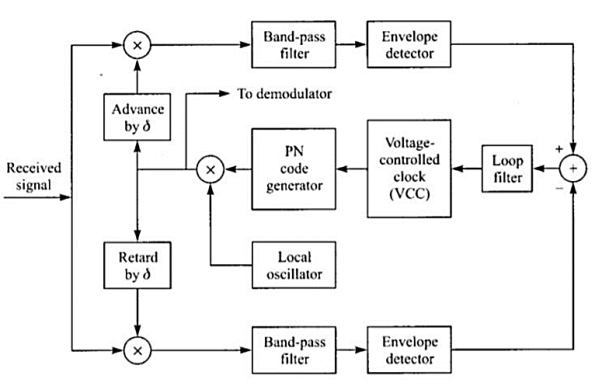
Figure 11: Delay-Locked Loop (DLL) for PN code tracking
The received DS spread spectrum signal is applied to two multipliers at the same time. The PN code for one of the multipliers is delayed by a fraction of the chip interval (δ). The identical PN code is sent to the other multiplier, but it is advanced by δ. Each multiplier's output is sent into a BPF centered on f0.
Each BPF's output is envelope detected and then subtracted. The loop filter, that drives the voltage-controlled oscillator receives this difference signal. The PN code generator uses the VCO as a clock. If the synchronization isn't perfect, one correlator's filtered output will surpass the other. As a result, the VCO will be advanced or postponed properly. The two filtered correlator outputs will be equally displaced from the peak value at the equilibrium point. The output of the PN code generator will then be perfectly synchronized with the received signal supplied into the demodulator.
B) FH Spread spectrum system:
Figure shows a common tracking method for FH spread spectrum communications.
The received signal and the receiver clock have a minor timing error, despite the initial acquisition is successful. The bandwidth of the BPF is on the order of 1/Tc, where Tc is the chip interval, and it is tuned to a single intermediate frequency. Its output is envelope detected before being multiplied by the clock signal to provide a three-level signal. The loop filter is activated by this.

Figure 12: Tracking loop for FH signals
Assume that the chip transitions from the locally generated sinusoidal waveform do not coincide with the incoming signal transitions. The loop filter's output will thus be either positive or negative, depending on whether the VCO is trailing or ahead of the input signal's time. The control signal for changing the VCO timing signal to drive the frequency synthesizer output to appropriate synchronization with the received signal will come from the error signal from the loop filter.
a) Reduced interference: In SS systems, interference from undesired sources is considerably reduced due to the processing gain of the system.
b) Low susceptibility to multi-path fading: Because of its inherent frequency diversity properties, a spread spectrum system offers resistance to degradation in signal quality due to multi-path fading. This is particularly beneficial for designing mobile communication systems.
c) Co-existence of multiple systems: With proper design of pseudo-random sequences, multiple spread spectrum systems can co-exist.
d) Immunity to jamming: An important feature of spread spectrum is its ability to withstand strong interference, sometimes generated by an enemy to block the communication link. This is one reason for extensive use of the concepts of spectrum spreading in military communications.
A specific example of the use of spread spectrum technology is the North American Code Division Multiple Access (CDMA) Digital Cellular (IS-95) standard. The CDMA employed in this standard uses a spread spectrum signal with 1.23-MHz spreading bandwidth. Since in a CDMA system every user is a source of interference to other users, control of the transmitted power has to be employed (due to near-far problem). Such control is provided by sophisticated algorithms built into control stations.
The standard also recommends use of forward error-correction coding with interleaving, speech activity detection and variable-rate speech encoding. Walsh code is used to provide 64 orthogonal sequences, giving rise to a set of 64 orthogonal ‘code channels’. The spread signal is sent over the air interface with QPSK modulation with Root Raised Cosine (RRC) pulse shaping. Other examples of using spread spectrum technology in commercial applications include satellite communications, wireless LANs based on IEEE 802.11 standard etc.
Satellite systems, mobile networks
Satellites are used to transfer information from one place to another using communication satellite on Earth’s orbit. Satellite communication began in 1957 and the first artificial satellite launched was Sputnik I by the USSR. The satellite communication can be one way as well. In this case the transmission of signal from the transmitter of first earth satellite and the receiver of the second earth satellite is in one direction.
In two-way communication the information is exchanged between the two earth stations. There are two uplinks and two downlinks required to achieve two ways communication.
The main elements of communication satellite are
a) Uplink
b) Transponders
c) Downlink
The block diagram of satellite communication is shown below. A communication satellite is basically a R.F repeater.
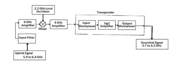
Fig 13. Block Diagram of Satellite Communication
The uplink frequencies used are of range 5.9GHz-6.4GHz these frequencies are converted to lower frequencies and amplified. The mixers and local oscillators are used to convert the higher frequency uplink signals to lower frequency signals. The com satellite receives this signal amplifies it and then transmits it so that there is no interference in the uplink and down link signals.
The transponders provide the medium for two-way communication. The downlink frequency used for transmission is from the range of 3.7GHz to 4.2GHz. The number of transponders per satellite depends upon the task which the satellite needs to do. For television broadcast two transponders are used in a satellite.
Advantages
The advantages of satellite communication are
- They are easy to install.
- The communication can be set up in every part of earth with the help of satellites.
- The network is controlled by the user.
- The elasticity of these circuits is excellent
Applications
The applications of satellite communication are
- Telephone
- Television
- Digital cinema
- Radio broadcasting
- Amateur radio
- Internet access
- Military
- Disaster Management
Wireless LAN IEEE 802.11
IEEE 802.11 is a set of standards carrying out wireless local area network (WLAN) computer communication in the 2.4, 3.6 and 5 GHz frequency bands. They are created and maintained by the IEEE LAN/MAN Standards Committee (IEEE 802)
802.11a — an extension to 802.11 that applies to wireless LANs and provides up to 54-Mbps in the 5GHz band. 802.11a uses an orthogonal frequency division multiplexing encoding scheme rather than FHSS or DSSS.
802.11b — an extension to 802.11 that applies to wireless LANS and provides 11 Mbps transmission in the 2.4 GHz band. 802.11b uses only DSSS. 802.11b was a 1999 ratification to the original 802.11 standard, allowing wireless functionality comparable to Ethernet.
802.11e — a wireless draft standard that defines the Quality of Service support for LANs, and is an enhancement to the 802.11a and 802.11b wireless LAN (WLAN) specifications. 802.11e adds QoS features and multimedia support to the existing IEEE 802.11b and IEEE 802.11a wireless standards, while maintaining full backward compatibility with these standards.
802.11g — applies to wireless LANs and is used for transmission over short distances at up to 54-Mbps in the 2.4 GHz bands.
802.11n — 802.11n builds upon previous 802.11 standards by adding multiple-input multiple-output. The additional transmitter and receiver antennas allow for increased data throughput through spatial multiplexing and increased range by exploiting the spatial diversity through coding schemes like Alamouti coding. The real speed would be 100 Mbit/s (even 250 Mbit/s in PHY level), and so up to 4-5 times faster than 802.11g.
- CDMA stands for Code Division Multiple Access. CDMA is a technique for spread spectrum multiple access.
- Data signals are XOReD with pseudorandom code and then transmitted over a channel.
- Different codes are used to modulate their signals, selection of code to modulate is important aspect as it relates with performance of system.
- In CDMA, single channel uses entire bandwidth and it does not share time as all stations transmit data simultaneously. Due to this CDMA differ from FDMA and TDMA.
- Let us assume we have 4 different stations A, B, C and D. All 4 stations connected to same channel. Data from station A is d1, B is d2, C is d3 and D is d4 similarly code assigned to A is C1, B is C2, C is C3 and D is C4.
- To transmit data, all 4 stations have multiplication strategy i.e. either code multiply by itself. It results in 4 stations or code multiply results in 4 stations or code multiply results in 4 station of code multiply by another, it results in zero station.
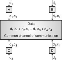
Fig. 14: Communication of station with code
- If station C and station D are talking to each other, D wants to listen whatever C is saying. It multiplies data on channel by C3 of station C.
- As C3 C3 is 4 and rest of combination i.e. C1 C3, C2 C3 and C4 C3 are all zero.
- Every station has some code, which is sequence of numbers known as chips.
- Sequence should be selected in proper manner to get appropriate codes. Orthogonal sequence has some properties:
- Multiplication of sequence by a scalar.
- Inner product of two equal sequences.
- Inner product of two different sequences.
- Sequence generation uses Walsh table to generate chip sequence.
- CDMA systems spread symbols. Before spreading symbols it uses distinctive code before transmission.
- On receiver side all symbols accepted by dispreading with help of correlating symbols. A signal which does not required are neither correlate nor de-spread to accept.
- CDMA signals are sequence of 0’s and 1’s and sequences are generated from code. Symbol per second means original data rate and chip rates means code chipping rate.
- Every code belongs to distinct set of data.
- CDMA allows space, time frequency signals transmission. Different coding method used in CDMA are:
(a) Autocorrelation codes
(i) Barker code.
(ii) Pseudo-noise code.
(b) Other important codes
(i) Orthogonal codes.
(ii) Walsh codes.
(iii) Scrambling codes.
(iv) Channelization codes.
(v) Carrier modulation codes.
- The Orthogonal Frequency Division Multiplexing (OFDM) transmission scheme is the optimum version of the multicarrier transmission scheme. In the past, as well as in the present, the OFDM is referred in the literature Multi-carrier, Multi-tone and Fourier Transform.
- In mid-1960 parallel data transmission and frequency multiplexing came. In high-speed digital communication OFMD is employed. OFMD has a drawback of massive complex computation and high-speed memory which are no more problems now due to introduction of DSP and VLSI.
- The implementation of this technology is cost effective as FFT eliminates array of sinusoidal generators and coherent demodulation required in parallel data systems· The data to be transmitted is spread over large number of carriers. Each of them is then modulated at low rates. By choosing proper frequency between them the carriers are made orthogonal to each other.
- In OFDM the spectral overlapping among the sun carrier is allowed, at the receiver due to orthogonality the subcarriers can be separated. This provides better spectral efficiency and use to steep BPF is eliminated.
- The problems arising in single carrier scheme are eliminated in OFDM transmission system. It has the advantage of spreading out a frequency selective fade over many symbols. This effectively randomizes burst errors caused by fading or impulse interference so that instead of several adjacent symbols being completely destroyed, many symbols are only slightly distorted.
- Because of this reconstruction of majority of them even without forward error correction is possible. As the entire bandwidth is divided into many narrow bandwidths, the sub and become smaller than the coherent bandwidth of the channel which makes the frequency response over individual sub bands is relatively flat. Hence, equalization becomes much easier than in single carrier system and it can be avoided altogether if differential encoding is employed.
- The orthogonality of sub channels in OFDM can be maintained and individual subchannels can be completely separated by the FFT at the receiver when there are no inter symbol interference (ISI) and intercarrier interference (ICI) introduced by the transmission channel distortion.
- Since the spectra of an OFDM signal is not strictly band limited, linear distortions such as multipath propagation causes each subchannel to spread energy into the adjacent channels and consequently cause ISI.
- One way to prevent ISI is to create a cyclically extended guard interval, where each OFDM symbol is preceded by a periodic extension of the signal itself. When the guard interval is longer than the channel impulse response or multipath delay, the ISI can be eliminated.
- By using time and frequency diversity, OFDM provides a means to transmit data in a frequency selective channel. However, it does not suppress fading itself. Depending on their position in the frequency domain, individual subchannels could be affected by fading.
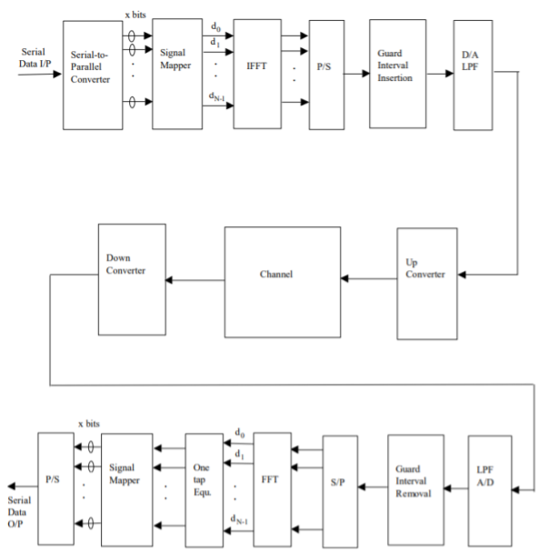
Fig 15: General OFDM System
The incoming signal is converted to parallel form by serial to parallel converter. After that it is grouped in x bits to form a complex number. These numbers are then modulated in a baseband manner by IFFT. Then through parallel to serial converted they are converted to serial data and transmitted. In order to avoid inter symbol interference a guard interval is inserted between the symbols. The discrete symbols are converted to analog and lowpass filtered for RF up-conversion. The receiver performs the inverse process of the transmitter. One tap equalizer is used to correct channel distortion. The tap coefficients of the filter are calculated based on channel information.
Key takeaway
The OFDM scheme differs from traditional FDM in the following interrelated ways:
- Multiple carriers (called subcarriers) carry the information stream
- The subcarriers are orthogonal to each other.
- A guard interval is added to each symbol to minimize the channel delay spread and inter-symbol interference.
References:
1. Lathi B.P. - Modern Digital and Analog communications systems - PRISM Indian Ed.
2. Digital Communication: J.S.Chitode
3. Digital Communication (Fundamentals & applications): Bernard Scalr
4. Introduction to Error Control Codes: Salvatore Gravano
5. OFDM For wireless communication systems: Ramjee Prasad
6. Modern Communication systems (Principles and application): Leon W. Couch II (PHI)
7. Error Control Coding: Shu Lin & Daniel J.Costello
Unit - 6
Spread - Spectrum methods
- Pseudo-Noise (PN) also known Pseudo Random Binary Sequence (PRBS).
- A Pseudo-Noise code (PN-code) or Pseudo Random Noise Code (PRN code) is a spectrum which generated deterministically by random sequence.
- PN sequence is random occurance of 0’s and 1’s bit stream.
- Directly sequence spread spectrum (DS-SS) system is most popular sequence in DS-SS system bits of PN sequence is known as chips and inverse of its period is known as chip rate.
In frequency hopping spread spectrum (FH-SS) sequence, channel number are pseudo random sequences and hop rate are inverse of its period.
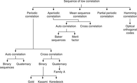
Fig. 1: Overview of PN sequence
Properties
(i) Balance property:
Total no. Of 1’s is more than no. Of 0’s in maximum length sequence.
(ii) Run property 1’s and 0’s stream shows length sequence, every fraction relate some meaning.
Rum | Length |
1/2 | 1 |
1/4 | 2 |
1/8 | 3 |
(iii) Correlation property:
If compared sequences are found similar then it is auto correlation.
If compared sequences are found mismatched then it is cross correlation.
Let (K) and y (K) are two sequences then correlation R (m) will be:

Correlation R (m) in pattern of digital bit sequence will be:

y1 = P1 q1
y1 = 0 if P1 q1
y1 = 1 if P1 = q1
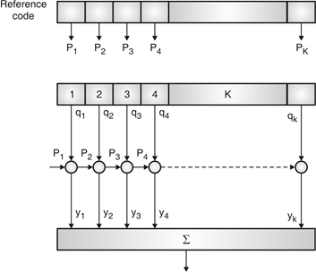
Fig. 2: Correlator
Fig. Shows Pi is a sequence which shifts through K bit shift register. K is length of correlate. Output achieved by K XNOR gate after comparison.
(iv) Shift and add:
By using X-OR gate, shift sequence modulo-2 added to upshifted sequence.
PN sequence generation methodologies:
(i) Using shift register with feedback.
(ii) Series parallel method for high speed PN generation.
(iii) Avoiding zero state.
(iv) Barker sequence.
(v) Kasami sequence.
(vi) Gold sequence.
Direct Sequence Spread Spectrum (DSSS) using BPSK modulation, so the first reversing switch introduces 180 degree phase reversals according to a pseudo-random code, while the second introduces the same reversals to reconstitute the original, narrow-band signal. The output is a “recompressed” narrow-band signal.
DSSS is a spread spectrum modulation technique used for digital signal transmission over airwaves. It was originally developed for military use, and employed difficult-to-detect wideband signals to resist jamming attempts.
It is also being developed for commercial purposes in local and wireless networks.
The stream of information in DSSS is divided into small pieces, each associated with a frequency channel across spectrums. Data signals at transmission points are combined with a higher data rate bit sequence, which divides data based on a spreading ratio. The chipping code in a DSSS is a redundant bit pattern associated with each bit transmitted.
This helps to increase the signal's resistance to interference. If any bits are damaged during transmission, the original data can be recovered due to the redundancy of transmission.
The entire process is performed by multiplying a radio frequency carrier and a pseudo-noise (PN) digital signal. The PN code is modulated onto an information signal using several modulation techniques such as quadrature phase-shift keying (QPSK), binary phase-shift keying (BPSK), etc. A doubly-balanced mixer then multiplies the PN modulated information signal and the RF carrier. Thus, the TF signal is replaced with a bandwidth signal that has a spectral equivalent of the noise signal. The demodulation process mixes or multiplies the PN modulated carrier wave with the incoming RF signal. The result produced is a signal with a maximum value when two signals are correlated. Such a signal is then sent to a BPSK demodulator. Although these signals appear to be noisy in the frequency domain, bandwidth provided by the PN code permits the signal power to drop below the noise threshold without any loss of information.
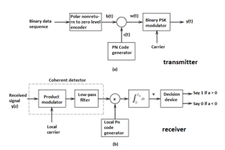
Fig 3(a) Transmitter (b) Receiver of DS-SS Technique
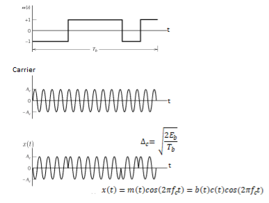
Fig 4 Wave forms for DSSS
Key takeaway
- In practice, the transmitter and receiver of Figures shown above are followed. In the transmitter spectrum spreading is performed prior to phase modulation. Also phase demodulation is done first and then despreading is done second, in the receiver.
- In the model of DS spread spectrum BPSK system used for analysis, the order of these two operations is interchanged. In the transmitter, BPSK is done first and spectrum spreading is done subsequently. Similarly, at the receiver also, spectrum de spreading is done first and then phase demodulation is done second.
- This is possible, because the spectrum spreading and BPSK are both linear operations.

Fig. 5: General spread spectrum structure
- Spread spectrum is specially used for wireless communication signal spreading. Transmitted signals frequency varies deliberately.
- Frequency hopping and direct sequence are two popular spread spectrums.
- In frequency hopping, signals are broadcast over any random series of frequency while in direct sequence each bit is in order of multiple bit of transmitting signal it uses chipping code.
Frequency Hoping Spread Spectrum (FHSS)
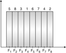
Fig. 6: Channel assignment
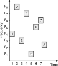
Fig. 7: Channel use
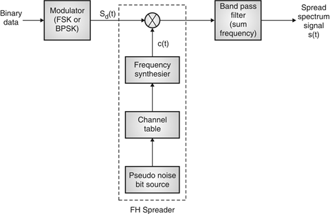
Fig. 8: FHSS (Transmitter)
In FHSS, according to PN sequence RF carries frequency used to get change.
FHSS has two types
1. Fast hopped FHSS.
2. Slow hopped FHSS.
Hopping is done with faster rate compared to bit rate in fast hopped FHSS while slow rate compared to message bit rate in slow hopped FHSS.
FHSS systems rely on changes in RF carrier frequencies which turn into burst errors.
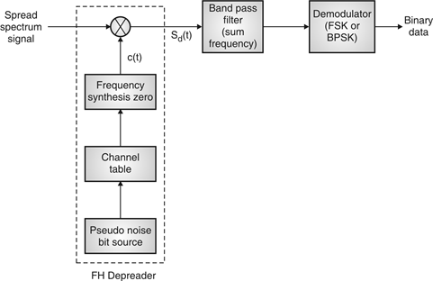
Fig. 9: FHSS (Receiver)
Performance
Sr. No. | Parameter | Slow frequency hopping | Fast frequency hopping |
1 | Definition | Multiple symbols are transmitted in one frequency hop. | Multiple hops are taken to transmit one symbol. |
2 | Chip rate | Symbol rate is equal to chip rate. | Hop rate is equal to chip rate. |
3 |   | Hop rate is lower than symbol rate. | Hop rate is higher than symbol rate. |
4 | Carrier frequencies | One or more symbols are transmitted over the same carrier frequency. | One symbol is transmitted over multiple carriers in different hops. |
5 | Jammer interference | This signal can be detected by jammer if carrier frequency in one hop is known. | This signal is difficult to detect since one symbol is transmitted on multiple carrier frequencies. |
Synchronization is the process of ensuring that the locally produced carrier at the receiver is in frequency and phase synchronism with the carrier at the transmitter. For successful functioning in spread spectrum communication systems, the transmitted and received PN codes must be perfectly matched.
(i) Both the carrier frequency and the PN clock can drift with time.
(ii) If the transmitter and receiver are moving relative to one other, as in mobile and satellite spread spectrum systems, the carrier and PN clocks will experience Doppler frequency shift.
As a result, the receiver's PN sequence must be synchronized with the transmitter's.
Synchronization steps:
The synchronization of the locally generated spreading signal with the incoming spread spectrum signal normally takes two phases. They are:
1) Acquisition: Bringing the two spreading signals into coarse alignment with one another implies the acquisition stage.
2) Tracking: After acquiring the received spread-spectrum signal, the second phase, tracking, is used to fine-tune the alignment.
The feedback loop is used in both acquisition and tracking.
Acquisition:
There are three types of acquisition schemes. They are
1) Serial search acquisition
2) Parallel search acquisition
3) Sequential search acquisition
1. Serial search acquisition:
A) DS Spread spectrum systems:
In Direct Sequence spread spectrum systems, the serial search scheme is shown in Figure.
Between the transmitter and the receiver, there is always some initial timing ambiguity. Assume the transmitter contains N chips and each chip has a Tc duration. It's important to linger for Td=NTc to verify synchronism at each time instant if initial synchronization is to take place in the face of additive noise and other interference. In(coarse) time steps of 1/2 Tc, we search throughout the time uncertainty interval.
The incoming PN signal and the locally produced PN signal are linked. The output signal is compared to a predefined threshold at specified search intervals of NTc (search dwell time). The locally produced code signal is advanced in time by 1/2Tc seconds if the output is less than the threshold. The procedure of correlation is carried out once more. These actions continue until a signal is detected or a threshold is reached. After then, it's presumed that the PN code was obtained.
As a result, assuming the initial misalignment between the two codes was n chips, the entire acquisition time is equal to
Tacq = 2nNTc seconds
B) FH spread spectrum systems
The serial search strategy for frequency hopping spread spectrum systems is shown in Figure.
A mixer is followed by a bandpass filter (BPF) and a square-law envelope detector in this non-coherent matched filter. The frequency hopper is controlled by the PN code generator. When the local hopping matches that of the received signal, the acquisition is finished.
Let fi be the frequency of the transmitter's frequency synthesizer. Assume that fj is the frequency of the signal generated by the frequency synthesizer in the receiver's acquisition circuit. If fi ≠ fj, the output of BPF will only create a little voltage less than the threshold. If fi = fj at a later time during the search, a huge voltage above the threshold will be created at the BPF output. This means that local hopping is matched with the received signal.
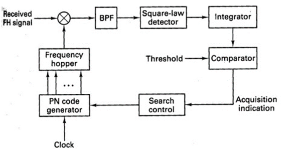
Figure 10. Frequency hopping serial search acquisition
2. Parallel search acquisition
By running two or more correlators in parallel, the parallel search acquisition approach adds a level of parallelism to the process. They'll look for periods that don't overlap. The search time is lowered with this system, but the implementation is more complex and costly.
3. Sequential search acquisition
The dwell time at each delay in the search process is made variable using a correlator with a variable integration period whose (biased) output is compared to two thresholds in this method. As a result, the sequential search strategy produces a more efficient search by reducing the average search time.
Tracking
The initial search process is halted after the signal has been acquired, and fine synchronization and tracking may start. The PN code generator at the receiver is kept in sync with the incoming signal thanks to the tracking. Fine chip synchronization and carrier phase tracking are both included in tracking for coherent demodulation.
A) DS Spread spectrum system:
The Delay-locked loop (DLL) is a common tracking loop for a Direct sequence spectrum signal, as shown in Figure.
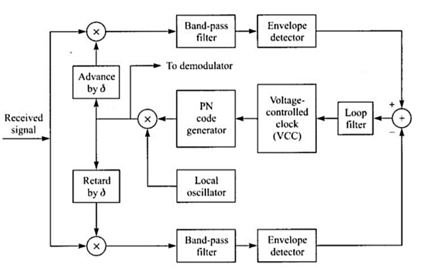
Figure 11: Delay-Locked Loop (DLL) for PN code tracking
The received DS spread spectrum signal is applied to two multipliers at the same time. The PN code for one of the multipliers is delayed by a fraction of the chip interval (δ). The identical PN code is sent to the other multiplier, but it is advanced by δ. Each multiplier's output is sent into a BPF centered on f0.
Each BPF's output is envelope detected and then subtracted. The loop filter, that drives the voltage-controlled oscillator receives this difference signal. The PN code generator uses the VCO as a clock. If the synchronization isn't perfect, one correlator's filtered output will surpass the other. As a result, the VCO will be advanced or postponed properly. The two filtered correlator outputs will be equally displaced from the peak value at the equilibrium point. The output of the PN code generator will then be perfectly synchronized with the received signal supplied into the demodulator.
B) FH Spread spectrum system:
Figure shows a common tracking method for FH spread spectrum communications.
The received signal and the receiver clock have a minor timing error, despite the initial acquisition is successful. The bandwidth of the BPF is on the order of 1/Tc, where Tc is the chip interval, and it is tuned to a single intermediate frequency. Its output is envelope detected before being multiplied by the clock signal to provide a three-level signal. The loop filter is activated by this.

Figure 12: Tracking loop for FH signals
Assume that the chip transitions from the locally generated sinusoidal waveform do not coincide with the incoming signal transitions. The loop filter's output will thus be either positive or negative, depending on whether the VCO is trailing or ahead of the input signal's time. The control signal for changing the VCO timing signal to drive the frequency synthesizer output to appropriate synchronization with the received signal will come from the error signal from the loop filter.
a) Reduced interference: In SS systems, interference from undesired sources is considerably reduced due to the processing gain of the system.
b) Low susceptibility to multi-path fading: Because of its inherent frequency diversity properties, a spread spectrum system offers resistance to degradation in signal quality due to multi-path fading. This is particularly beneficial for designing mobile communication systems.
c) Co-existence of multiple systems: With proper design of pseudo-random sequences, multiple spread spectrum systems can co-exist.
d) Immunity to jamming: An important feature of spread spectrum is its ability to withstand strong interference, sometimes generated by an enemy to block the communication link. This is one reason for extensive use of the concepts of spectrum spreading in military communications.
A specific example of the use of spread spectrum technology is the North American Code Division Multiple Access (CDMA) Digital Cellular (IS-95) standard. The CDMA employed in this standard uses a spread spectrum signal with 1.23-MHz spreading bandwidth. Since in a CDMA system every user is a source of interference to other users, control of the transmitted power has to be employed (due to near-far problem). Such control is provided by sophisticated algorithms built into control stations.
The standard also recommends use of forward error-correction coding with interleaving, speech activity detection and variable-rate speech encoding. Walsh code is used to provide 64 orthogonal sequences, giving rise to a set of 64 orthogonal ‘code channels’. The spread signal is sent over the air interface with QPSK modulation with Root Raised Cosine (RRC) pulse shaping. Other examples of using spread spectrum technology in commercial applications include satellite communications, wireless LANs based on IEEE 802.11 standard etc.
Satellite systems, mobile networks
Satellites are used to transfer information from one place to another using communication satellite on Earth’s orbit. Satellite communication began in 1957 and the first artificial satellite launched was Sputnik I by the USSR. The satellite communication can be one way as well. In this case the transmission of signal from the transmitter of first earth satellite and the receiver of the second earth satellite is in one direction.
In two-way communication the information is exchanged between the two earth stations. There are two uplinks and two downlinks required to achieve two ways communication.
The main elements of communication satellite are
a) Uplink
b) Transponders
c) Downlink
The block diagram of satellite communication is shown below. A communication satellite is basically a R.F repeater.
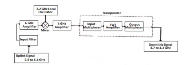
Fig 13. Block Diagram of Satellite Communication
The uplink frequencies used are of range 5.9GHz-6.4GHz these frequencies are converted to lower frequencies and amplified. The mixers and local oscillators are used to convert the higher frequency uplink signals to lower frequency signals. The com satellite receives this signal amplifies it and then transmits it so that there is no interference in the uplink and down link signals.
The transponders provide the medium for two-way communication. The downlink frequency used for transmission is from the range of 3.7GHz to 4.2GHz. The number of transponders per satellite depends upon the task which the satellite needs to do. For television broadcast two transponders are used in a satellite.
Advantages
The advantages of satellite communication are
- They are easy to install.
- The communication can be set up in every part of earth with the help of satellites.
- The network is controlled by the user.
- The elasticity of these circuits is excellent
Applications
The applications of satellite communication are
- Telephone
- Television
- Digital cinema
- Radio broadcasting
- Amateur radio
- Internet access
- Military
- Disaster Management
Wireless LAN IEEE 802.11
IEEE 802.11 is a set of standards carrying out wireless local area network (WLAN) computer communication in the 2.4, 3.6 and 5 GHz frequency bands. They are created and maintained by the IEEE LAN/MAN Standards Committee (IEEE 802)
802.11a — an extension to 802.11 that applies to wireless LANs and provides up to 54-Mbps in the 5GHz band. 802.11a uses an orthogonal frequency division multiplexing encoding scheme rather than FHSS or DSSS.
802.11b — an extension to 802.11 that applies to wireless LANS and provides 11 Mbps transmission in the 2.4 GHz band. 802.11b uses only DSSS. 802.11b was a 1999 ratification to the original 802.11 standard, allowing wireless functionality comparable to Ethernet.
802.11e — a wireless draft standard that defines the Quality of Service support for LANs, and is an enhancement to the 802.11a and 802.11b wireless LAN (WLAN) specifications. 802.11e adds QoS features and multimedia support to the existing IEEE 802.11b and IEEE 802.11a wireless standards, while maintaining full backward compatibility with these standards.
802.11g — applies to wireless LANs and is used for transmission over short distances at up to 54-Mbps in the 2.4 GHz bands.
802.11n — 802.11n builds upon previous 802.11 standards by adding multiple-input multiple-output. The additional transmitter and receiver antennas allow for increased data throughput through spatial multiplexing and increased range by exploiting the spatial diversity through coding schemes like Alamouti coding. The real speed would be 100 Mbit/s (even 250 Mbit/s in PHY level), and so up to 4-5 times faster than 802.11g.
- CDMA stands for Code Division Multiple Access. CDMA is a technique for spread spectrum multiple access.
- Data signals are XOReD with pseudorandom code and then transmitted over a channel.
- Different codes are used to modulate their signals, selection of code to modulate is important aspect as it relates with performance of system.
- In CDMA, single channel uses entire bandwidth and it does not share time as all stations transmit data simultaneously. Due to this CDMA differ from FDMA and TDMA.
- Let us assume we have 4 different stations A, B, C and D. All 4 stations connected to same channel. Data from station A is d1, B is d2, C is d3 and D is d4 similarly code assigned to A is C1, B is C2, C is C3 and D is C4.
- To transmit data, all 4 stations have multiplication strategy i.e. either code multiply by itself. It results in 4 stations or code multiply results in 4 stations or code multiply results in 4 station of code multiply by another, it results in zero station.
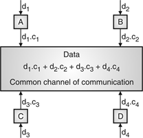
Fig. 14: Communication of station with code
- If station C and station D are talking to each other, D wants to listen whatever C is saying. It multiplies data on channel by C3 of station C.
- As C3 C3 is 4 and rest of combination i.e. C1 C3, C2 C3 and C4 C3 are all zero.
- Every station has some code, which is sequence of numbers known as chips.
- Sequence should be selected in proper manner to get appropriate codes. Orthogonal sequence has some properties:
- Multiplication of sequence by a scalar.
- Inner product of two equal sequences.
- Inner product of two different sequences.
- Sequence generation uses Walsh table to generate chip sequence.
- CDMA systems spread symbols. Before spreading symbols it uses distinctive code before transmission.
- On receiver side all symbols accepted by dispreading with help of correlating symbols. A signal which does not required are neither correlate nor de-spread to accept.
- CDMA signals are sequence of 0’s and 1’s and sequences are generated from code. Symbol per second means original data rate and chip rates means code chipping rate.
- Every code belongs to distinct set of data.
- CDMA allows space, time frequency signals transmission. Different coding method used in CDMA are:
(a) Autocorrelation codes
(i) Barker code.
(ii) Pseudo-noise code.
(b) Other important codes
(i) Orthogonal codes.
(ii) Walsh codes.
(iii) Scrambling codes.
(iv) Channelization codes.
(v) Carrier modulation codes.
- The Orthogonal Frequency Division Multiplexing (OFDM) transmission scheme is the optimum version of the multicarrier transmission scheme. In the past, as well as in the present, the OFDM is referred in the literature Multi-carrier, Multi-tone and Fourier Transform.
- In mid-1960 parallel data transmission and frequency multiplexing came. In high-speed digital communication OFMD is employed. OFMD has a drawback of massive complex computation and high-speed memory which are no more problems now due to introduction of DSP and VLSI.
- The implementation of this technology is cost effective as FFT eliminates array of sinusoidal generators and coherent demodulation required in parallel data systems· The data to be transmitted is spread over large number of carriers. Each of them is then modulated at low rates. By choosing proper frequency between them the carriers are made orthogonal to each other.
- In OFDM the spectral overlapping among the sun carrier is allowed, at the receiver due to orthogonality the subcarriers can be separated. This provides better spectral efficiency and use to steep BPF is eliminated.
- The problems arising in single carrier scheme are eliminated in OFDM transmission system. It has the advantage of spreading out a frequency selective fade over many symbols. This effectively randomizes burst errors caused by fading or impulse interference so that instead of several adjacent symbols being completely destroyed, many symbols are only slightly distorted.
- Because of this reconstruction of majority of them even without forward error correction is possible. As the entire bandwidth is divided into many narrow bandwidths, the sub and become smaller than the coherent bandwidth of the channel which makes the frequency response over individual sub bands is relatively flat. Hence, equalization becomes much easier than in single carrier system and it can be avoided altogether if differential encoding is employed.
- The orthogonality of sub channels in OFDM can be maintained and individual subchannels can be completely separated by the FFT at the receiver when there are no inter symbol interference (ISI) and intercarrier interference (ICI) introduced by the transmission channel distortion.
- Since the spectra of an OFDM signal is not strictly band limited, linear distortions such as multipath propagation causes each subchannel to spread energy into the adjacent channels and consequently cause ISI.
- One way to prevent ISI is to create a cyclically extended guard interval, where each OFDM symbol is preceded by a periodic extension of the signal itself. When the guard interval is longer than the channel impulse response or multipath delay, the ISI can be eliminated.
- By using time and frequency diversity, OFDM provides a means to transmit data in a frequency selective channel. However, it does not suppress fading itself. Depending on their position in the frequency domain, individual subchannels could be affected by fading.
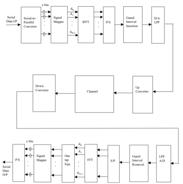
Fig 15: General OFDM System
The incoming signal is converted to parallel form by serial to parallel converter. After that it is grouped in x bits to form a complex number. These numbers are then modulated in a baseband manner by IFFT. Then through parallel to serial converted they are converted to serial data and transmitted. In order to avoid inter symbol interference a guard interval is inserted between the symbols. The discrete symbols are converted to analog and lowpass filtered for RF up-conversion. The receiver performs the inverse process of the transmitter. One tap equalizer is used to correct channel distortion. The tap coefficients of the filter are calculated based on channel information.
Key takeaway
The OFDM scheme differs from traditional FDM in the following interrelated ways:
- Multiple carriers (called subcarriers) carry the information stream
- The subcarriers are orthogonal to each other.
- A guard interval is added to each symbol to minimize the channel delay spread and inter-symbol interference.
References:
1. Lathi B.P. - Modern Digital and Analog communications systems - PRISM Indian Ed.
2. Digital Communication: J.S.Chitode
3. Digital Communication (Fundamentals & applications): Bernard Scalr
4. Introduction to Error Control Codes: Salvatore Gravano
5. OFDM For wireless communication systems: Ramjee Prasad
6. Modern Communication systems (Principles and application): Leon W. Couch II (PHI)
7. Error Control Coding: Shu Lin & Daniel J.Costello