Unit - 2
Fluid Dynamics
- Navier-Stokes equation, in fluid mechanics, a partial differential equation that describes the go with the drift of incompressible fluids.
- The equation is a generalization of the equation devised with the aid of using Swiss mathematician Leonhard Euler withinside the 18th century to explain the go with the drift of incompressible and frictionless fluids.
- The Navier-Stokes equation, in cutting-edge notation, is

Wherein, u is the fluid pace vector, P is the fluid pressure, ρ is the fluid density, is density, and ∇ is the Laplacian operator.
They are on occasion followed with the aid of using an equation of kingdom bearing on stress, temperature and density. They stand up from making use of Isaac Newton's 2d regulation to fluid motion, collectively with the belief that the strain with inside the fluid is the sum of a diffusing viscous term (proportional to the gradient of velocity) and a stress term—as a result describing viscous float.
The distinction among them and the intently associated Euler equations is that Navier–Stokes equations take viscosity into consideration whilst the Euler equations version simplest in viscid float. As a result, the Navier–Stokes are a parabolic equation and consequently have higher analytic properties, on the cost of getting much less mathematical structure (e.g. They may be by no means absolutely integral). The Navier–Stokes equations are beneficial due to the fact they describe the physics of many phenomena of medical and engineering interest.
They can be used to version the weather, ocean currents, water float in a pipe and air float round a wing. The Navier–Stokes equations, of their complete and simplified forms, assist with the layout of plane and cars, the observe of blood float, the layout of electricity stations, the evaluation of pollution, and plenty of different things. Coupled with Maxwell's equations, they may be used to version and observe magneto hydrodynamics.
Key Takeaways:
- The equation is a generalization of the equation devised with the aid of using Swiss mathematician Leonhard Euler withinside the 18th century to explain the go with the drift of incompressible and frictionless fluids.
- The Navier-Stokes equation, in cutting-edge notation, is

- Consider steady flow of an ideal fluid along the shown tube.
- Separate out a small element of fluid of cross- sectional area dA and length ds from stream tube as a free body from the during fluid.
- Fig. Shows such a small elements LM of fluid of cross Section area dA and length ds.
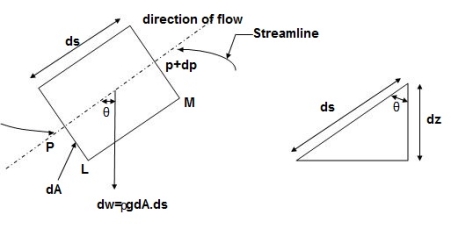
Fig 1: Equation of motion Diagram
- Let, p= Pressure of the elements at L
p + dp = Pressure on the element at M, and
V=Velocity of the fluid element.
- The external forces tending to accelerate the fluid elements in the direction of streamline are as follows:
- Net pressure force in the direction of flows is, p.dA – (p+dp)dA = -dp. DA
- Component of the weight of the fluid elements in the direction of flows is
= -.g.dA.ds.cos
=- .g.dA.ds (dz/ds) (:. Cos = dz/ds)
= - .g.dA.dz
- Mass flow of the fluid element = .dA.ds
- The Acceleration of the fluid element,
a = dv/dt = dv/ds * ds/dt = v. Dv/ds
- Now, according to Newton’s second law of motion, force= mass x acceleration.
∴ – dp. DA.- .g.dA.dz= .dA.ds x v.dv/ds
Dividing both sides by rho. DA, we get
-dp/-. g.dz= v.dv
Or dp/ + v.dv + g.dz=0
- This is the required Euler’s equation for motion.
Integrating the Euler’s equation of motion, we get
1/ ∫ d p +∫v. d v+ ∫g.dz=constant
p/ ρ + v2 /2 + g z = constant
Dividing by g, we get
p/ g + v 2/2g + z = constant
p /w + v 2/2g + z = constant
Or in other words, P1/ W+V1 2 / 2 g +Z1=P2/ W+V22 / 2g+Z2
Which proves Bernoulli’s equation.
Key takeaways
Euler equation is given as -
P1/ W+V1 2 / 2 g +Z1=P2/ W+V22 / 2g+Z2
It states that the sum of kinetic, potential and pressure heads of a fluid particle is constant along a streamline during steady flow when compressibility and frictional effects are negligible. i.e., For an ideal fluid, total head of fluid particle remains constant during a steady-incompressible flow.
Or
Total head along a streamline is constant during steady flow when compressibility and frictional effects are negligible.
The total mechanical energy of the moving fluid comprising the gravitational potential energy of elevation, the energy associated with the fluid pressure and the kinetic energy of the fluid motion, remains constant.
Total head = Z + 

H1 = H2
Derivation of Bernoulli’s Equation:
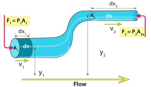
Fig 2: Bernoulli’s Theorem
Assumptions:
- The density of the incompressible fluid remains constant at both points.
- The energy of the fluid is conserved as there are no viscous forces in the fluid.
Therefore, the work done on the fluid is given as:
DW = F1dx1 – F2dx2
DW = p1A1dx1 – p2A2dx2
DW = p1dV – p2dV = (p1 – p2) dV
We know that the work done on the fluid was due to conservation of gravitational force and change in kinetic energy. The change in kinetic energy of the fluid is given as:
DK=1/2(m2v22) −1/2(m1v12) =1/2ρdV(v22−v12)
The change in potential energy is given as:
DU = mgy2 – mgy1 = ρdVg (y2 – y1)
Therefore, the energy equation is given as:
DW = dK + dU
(p1 – p2) dV = 1/2ρdV(v22−v12) + ρdVg (y2 – y1)
(p1 – p2) = 1/2 ρ(v22−v12) + ρg (y2 – y1)
Rearranging the above equation, we get
p1+1/2ρv12+ρgy1=p2+1/2ρv22+ρgy2
This is Bernoulli’s equation.
p1+1/2ρv12+ρgh1=p2+1/2ρv22+ρgh2
It is the important formula.
Applications of Bernoulli’s equation
Bernoulli’s equation is applied is all problems of incompressible fluid flow where energy considerations are involved, but we shall consider its applications to the following measuring devices:
- Venturi meter
- Pitot- tube
- Sub-merged orifice
- Orifice meters
- Rotameter.
Limitation of Bernoulli’s equation
- Velocity of every liquid particle, across any section of pipe is not uniform.
- Bernoulli’s equation is not applicable for fluid with unsteady flow.
- If fluid flowing in a curved path, the energy due to centrifugal force should be taken into account.
Key Takeaways:
- Total head along a streamline is constant during steady flow when compressibility and frictional effects are negligible.
- The density of the incompressible fluid remains constant at both points.
- The energy of the fluid is conserved as there are no viscous forces in the fluid.
- A pitot tube is the simple device used for measuring the velocity of the flow at the required point in a pipe or a stream. It is also called as impact tube or stagnation tube.
- It is based on the principle that if the velocity of flow at a point becomes zero, the pressure is increased due to conversion of kinetic energy into pressure energy.
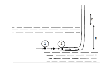
Fig 3: Pitot tube
- In its simple form, a pitot tube consists of a transparent glass tube bent through 90° and with ends unsealed.
- Diameter of tube is larger enough to neglect capillary effects.
- One leg called as the body is inserted into the flow at upstream and aligned with the direction of flow whereas the other leg, called as stem, is vertical and open to atmosphere.
- The liquid is rise in the tube due to changes in energy.
- The velocity is determined by measuring the rise in the tube.
- Consider a section 1 and 2 at a same level just in front of inlet of the tube.
Apply Bernoulli's equation

∴ Z₁ = Z₂ as they are at same level
V₂ = 0 because flow of particle is coming to rest at point 2.
h =Rise in tube,
H = Head of pressure at 1 (static head)
h+H = Stagnation head
Substitute above value in Bernoulli's Equation (1)
∴H+ =h+H ∴h=
V₁ = 
This is the theoretical velocity.
Actual velocity
V = Cv, Vtheoretical = Cv =
Where Cv= Coefficient of velocity
Key takeaways:
A pitot tube is the simple device used for measuring the velocity of the flow at the required point in a pipe or a stream. It is also called as impact tube or stagnation tube.
A venturi meter is a device used for measuring the rate of a flow of a fluid flowing through a pipe it consists of three parts:
- A short converging part,
- Throat, and
- Diverging Part
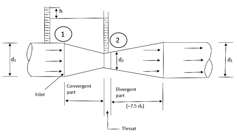
Fig 4: Venturimeter
It is based on the principle of Bernoulli’s equation.
Expression for Rate of flow through venturimeter:
Consider a venturimeter fitted in a horizontal pipe through which a fluid is following as shown in fig.
Let d 1 = diameter at inlet or at section (1)
P 1= pressure at section (1)
V 1= velocity of fluid at section (1)
A 1= area of section (1) =π/4. D2
And d 2, P 2, V 2, a 2 are corresponding values at section (2)
Applying Bernoulli’s equation at section (1) and (2) we get
P1/ g+V12 /2g+Z1=P2 / g+V22 /2g+Z2
As pipe is horizontal hence z 1 = z2
P1/ g+V12 /2g =P2 / g+V22 /2g
(P1 – p 2)/ g = V22 /2g - V12 /2g
But (P1 – p 2)/ g is the difference of pressure heads at section land 2 and it is equal to h
∴ (P1 – p 2)/ g =h
Substituting this value of (P1 – p 2)/ g in the above eqn we get.
∴ h = V22 /2g - V12 /2g…………... (1)
Now applying continuity equation at section 1 and
a 1 v 1 = a 2 v 2
∴ v 1 = a 2 v 2 / a 1
Substituting this value of v 1 in equation 1
h= V22 /2g – (a 2 v 2 / a 1) 2 / 2 g
h= V22 /2g [ (a 12 –a 22 )/ a 12 ]
V22 = (2 g h a 12 )/ (a 12 –a 22)
Q = a2 v 2
= [a 1 a 2 / ( a 12 –a 22 ) ] * ( 2 g h ) ]
Above equation gives the discharge under ideal conditions and is called, Theoretical discharge Actual discharge will be less than theoretical discharge.
Q act = C d * [a 1 a 2 / ( a 12 –a 22)] * (2 g h)]
Where C d = co-efficient of venturimeter and its value is less than 1.
Key Takeaways:
- A venturi meter is a device used for measuring the rate of a flow of a fluid flowing through a pipe
- Fully sub merged orifice is one which has its whole of the outlet side sub-merged under a liquid so that its discharges a jet of the liquid into the liquid of same kind.
- Fig shows fully submerged orifice.

- Consider two points 1 & 2, point 1 being in the reservoir on the up [stream side of the orifice & point 2 being at the vena contract as shown in fig.
H1 = Height of water above the top of the orifice on the upstream side,
H2 = Height of water above the top of the orifice on the downstream side,
H = Difference in water level.
b = Width of orifice,
Cd = Co-efficient of discharge.
Height of water above the center of the orifice on the upstream side,
= H1 + 
Height of water above the center of the orifice on the downstream side,
= 
Applying Bernoulli’s eqn. At 1 & 2


 V1 is negligible.


V2 = √2gH
Area of orifice = b (H2 – H1)
Q = Cd x b (H2 – H1) x √2gH
Flow through sharp edged circular orifice discharging free
An orifice is an opening in the wall or base of a vessel through which the fluid flows. The top edge of the orifice is always below the free surface.
Flow through an orifice
- Figure shows a small circular orifice with sharp edge in the side wall of a tank discharging free into the atmosphere.
- Let the orifice be at a depth H below the free surface.
- As the fluid flows through the orifice, it contracts and attains a parallel form at a distance d/2 from the plane of the orifice.
- The point at which the streamline first become parallel is termed as Vena contracta.
- Beyond this section, the jet diverges and is attracted in the downward direction by gravity.
Considering points 1 and 2 as shown in figure and applying Bernoulli’s theorem, we have

P1 = P2 = Pa
z1 = z2 + H
Further, if the cross-sectional area of the tank is very large, the liquid at point 1 is practically standstill and hence V1 = 0

V2 = √2gH
Key Takeaways:
Fully sub merged orifice is one which has its whole of the outlet side sub-merged under a liquid so that its discharges a jet of the liquid into the liquid of same kind.
- It is a device used for measuring the rate of flow of a fluid through a pipe.
- It is a cheaper device compared to venturimeter
- It also works on the same principle as that of venturimeters.
- It consists of a flat circle plate which has a circular shape edged holed called orifice, which is concentric with the pipe.
- The orifice diameter is kept generally 0.5 times the diameters of the pipe, though it may vary from 0.4 to 0.8 times the pipe diameters.
- Velocity at vena contracta V= Cv (2 g h)
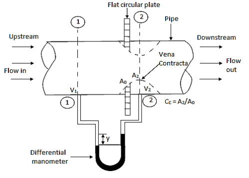
Fig 5: Orifice meter
Laminar Flow –
- A Laminar flow is one in which paths taken by the individual particles do not cross one another and move along well-defined path.
- E.g.: Flow of blood in veins and arteries.
Turbulent Flow –
- A turbulent flow is that flow in which fluid particles move in a zig zag way.
- E.g.: High velocity flows in conduit of large size.
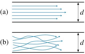
Fig 6: Laminar and turbulent flow
Key takeaways:
A Laminar flow is one in which paths taken by the individual particles do not cross one another and moves along well-defined path.
A turbulent flow is that flow in which fluid particles move in a zig zag way.
Also, we are able to outline it because the perpendicular pressure carried out according to unit vicinity of the object. And, whilst we say, a perpendicular pressure, we suggest to say, its miles pressure.
Differentiate Pressure from Stress
As you follow pressure, there's a form of pressure advanced at the adjoining floor of your each fingers. The pressure depth right here is the shear pressure. Pressure and shear pressure have one primary difference—that is, their direction. Pressure usually acts every day to the floor while shear pressure usually acts parallel to the floor. They are outside and inner entity respectively however that is out of debate right here.
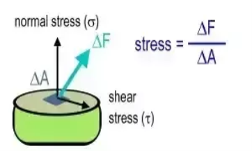
If you study above figure, willing pressure ‘delta F’ is visible appearing at the floor. For each case, strain is received via way of means of dividing pressure with vicinity. However, ordinary strain or strain is received via way of means of dividing the ordinary thing of pressure via way of means of the floor vicinity and shear strain is received via way of means of dividing horizontal thing of pressure via way of means of the equal floor vicinity.
So, the principle distinction among strain and shear strain is the earlier is ordinary and the later is parallel to the floor vicinity upon which the pressure is appearing.
Pressure
Let’s think which you have a vessel packed with water and stored it on the hearth place and cowl the vessel with a lid. Now because the temperature rises, the lid begins off evolved vibrating. You would possibly have found this occurring even as making ready a steamed meals item.
The technology in the back of it's far, on the microscopic level, water has hundreds of thousands of molecules bonded collectively with the interatomic pressure of attraction, because the temperature rises, the bond among the molecules spoil and that they begin colliding with every different and on the floor of the vessel, which, in turn, creates strain on the partitions of the vessel.
In Bernoulli’s precept, we found out that the rate distinction among the higher and the decrease circulate of the fluid creates a strain distinction, and this precept is beneficial in producing airlift.
Stress
If we speak approximately pressure, it's far a pressure carried out perpendicular to the location, so it's far truly associated with the matter. Let’s think that there's a block of mass ‘m’ positioned horizontally.
Now, in case you follow a pressure, pressure acts at a factor of the aircraft. Since pressure acts at a factor at the aircraft of the block, that’s why we remember pressure because the pressure appearing in step with unit location of the aircraft.
Since pressure has 3 parameters to outline it because the vector quantity. These are the magnitude, direction, and factor of application. We additionally referred to as pressure the ‘Second-order tensor’.
Open your left palm extensive and blow a punch on it together along with your proper fist. The pressure you're making use of right here together along with your proper fist is perpendicular or every day to the floor vicinity of your left palm.
The pressure depth—that is, the pressure which you follow together along with your proper hand in step with unit vicinity of your left palm, is referred to as Pressure. Now, you open eachhand and align them one over the other. Next, attempt to rub your fingers with every other.
Key Takeaways:
- Pressure usually acts every day to the floor while shear pressure usually acts parallel to the floor. They are outside and inner entity respectively however that is out of debate right here.
- So, the principle distinction among strain and shear strain is the earlier is ordinary and the later is parallel to the floor vicinity upon which the pressure is appearing.
- In Bernoulli’s precept, we found out that the rate distinction among the higher and the decrease circulate of the fluid creates a strain distinction, and this precept is beneficial in producing airlift.
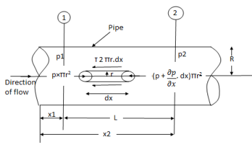
Fig7 : Circular pipe
Fig: Shows a horizontal circular pipe of radius R, having laminar flow of fluid through it.
Consider a small concentric cylinder of radius r and length dx as a free body.
If τis the shear stress, the shear force F is given by
F = τx 2 π r x dx
Let P be the intensity of pressure at left end and the intensity of pressure at the right end be ( P + 
Thus, the force acting on the fluid element are:
The shear force, τx 2πr x dx on the surface of fluid element.
The pressure force, P x πr2 on the left end.
The pressure force, ( P +  on the right end.
For steady flow, the net force on the cylinder must be zero.
∴ [P x πr2 - ( P +  ] – τ × 2πr × dx = 0
∴ -  ] – τ × 2πr × dx = 0
∴ τ = - .
. 
Shear stress is zero at the centre of pipe (r = 0) and maximum at the pipe wall given by
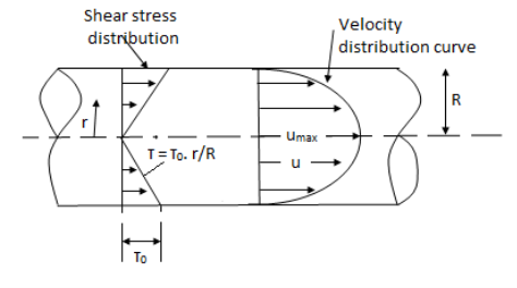
Fig 8: When shear stress is zero
∴ τ0 = -- .
. 
From Newton’s Law of viscosity
τ = μ. 
In this equation, the distance y is measured from the boundary. The radial distance r is related to distance y by the relation.
y = R-r ordinate y = -d r
∴ τ = - μ. 
Comparing two values of τ
∴ - μ.  -
- .
. 
 du =
du = 
Integrating the above equation w. r. t. ‘r’ we get
 u =
u = + C --------------- (ii)
Where C is the constant of integration and its value is obtained from the boundary conditions.
At r = R, u = 0
 0 =
0 =  + C or C =
Substituting this value of C in eqn. (ii) we get,
 u =
u = 
 u = -
u = -  (R2 – r2)
Shows that velocity distribution curve is a parabola.
The maximum velocity occurs, at the centre and is given by.
 umax = -
Turbulent flow
Turbulent flow occurs when the Reynolds number exceeds 4000.
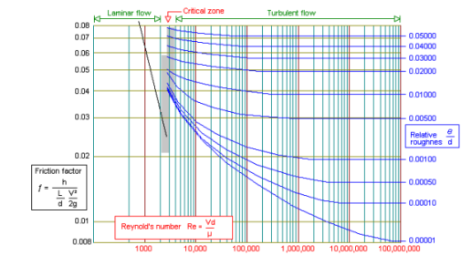
Eddy currents are present within the flow and the ratio of the internal roughness of the pipe to the internal diameter of the pipe needs to be considered to be able to determine the friction factor. In large diameter pipes the overall effect of the eddy currents is less significant. In small diameter pipes the internal roughness can have a major influence on the friction factor. The relative roughness of the pipe and the Reynolds number can be used to plot the friction factor on a friction factor chart. The friction factor can be used with the Darcy-Weisbach formula to calculate the frictional resistance in the pipe. Between the Laminar and Turbulent flow conditions (Re 2300 to Re 4000) the flow condition is known as critical. The flow is neither wholly laminar nor wholly turbulent. It may be considered as a combination of the two flow conditions. The friction factor for turbulent flow can be calculated from the Colebrook-White equation:

Turbulence is caused by excessive kinetic energy in parts of a fluid flow, which overcomes the damping effect of the fluid's viscosity. The mixing action of the turbulent flow enhances the temperature averaging effect in addition to the transfer of energy from the hot water to the surrounding fluid. When a hot object is cooled, the mixing action of turbulent flows in the fluid surrounding the object plays an important role in cooling it.
Key Takeaways:

Velocity distribution
- Due to the shear stress at the boundaries and due to the presence of the free liquid surface, the velocity in the open channel varies from point to point. The velocity may have components in all the three co-ordinate directions.
- In general, the components in the lateral direction are very small and hence are neglected. Only the component in the direction of flow is taken into account.
- The velocity distribution depends upon the geometry of the channel. The velocity distribution in some channel sections Lines of equal velocity is called as 'isovels'.
- At the boundary of the channel, velocity is zero and it goes on increasing as we go more and more away from the boundary.
- It can, however, be seen that the maximum velocity does not occur at the surface but occurs at a small distance below the free liquid surface.
- This is mainly due to secondary currents and not due to wind resistance at the free liquid surface. The maximum velocity is seen to occur at a distance of 0.05 y to 0.25 y from the free surface, where y is the depth of flow.
- The velocity distribution also depends upon the ratio of depth 'y and the width B of the channel known as the aspect ratio. Deeper and narrower the channel, deeper is the point of maximum velocity.
- A typical velocity profile. It is observed that the average velocity occurs at a distance of 0.6 y from the free liquid surface. Sometimes average velocity is taken an average of velocities at depth of 0.2 y and 0.8 y or

- The average velocity is slightly less than surface velocity and is about 0.8 to 0.85 times the surface velocity.
Key Takeaways:
- The velocity may have components in all the three co-ordinate directions.
- Only the component in the direction of flow is taken into account.
- It can, however, be seen that the maximum velocity does not occur at the surface but occurs at a small distance below the free liquid surface.
- Sometimes average velocity is taken an average of velocities at depth of 0.2 y and 0.8 y

References:
1. Introduction to Fluid Mechanics, James E.A., John and Haberm W.A., Prentice Hall of India
2. Fluid Mechanics, Jain A.K., Khanna Publication
3. Engineering Fluid Mechanics, Garde R.J. And MirajGoankar, Nemchand&Bros, Roorkee, SCITECH, Publication (India) Pvt. Ltd.
4. Fluid Mechanics and Fluid Power Engineering, Dr. D.S. Kumar, S.K. Kataria& sons
5. Fluid Mechanics, Frank M. White, McGraw Hill Publication
6. Fluid Mechanics, Cengel&Cimbla, Tata McGraw Hill