Unit - 4
Theory of turbo machines
1. Based on energy transfer
- Energy is given by fluid to the rotor – Power generating Turbo machine. E.g. Turbines
- Energy given by the rotor to the fluid - Power absorbing Turbo machine. E.g. Pumps, blowers and compressors
2. Based on fluid flowing in turbo machine
- Water
- Air
- Steam
- Hot gases
- Liquids like petrol etc.
3. Based on direction of flow through the impeller or vanes or blades, with reference to the axis of shaft rotation
- Axial flow – Axial pump, compressor or turbine.
- Mixed flow - Mixed flow pump, Francis turbine
- Radial flow - Centrifugal pump and compressor
- Tangential flow - Pelton water turbine
4. Based on condition of fluid in turbo machine
- Impulse type ( constant pressure) E.g. Pelton water turbine
- Reaction type (variable pressure) E.g. Francis reaction turbines
5. Based on position of rotating shaft
- Horizontal shaft – Steam turbines
- Vertical shaft - Kaplan water turbines
- Inclined shaft - Modern bulb micro
Key Takeaways:
- Energy is given by fluid to the rotor – Power generating Turbo machine. E.g. Turbines
- Axial flow – Axial pump, compressor or turbine.
- Impulse type (constant pressure) E.g. Pelton water turbine
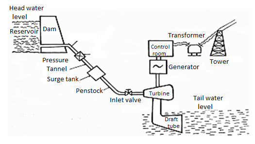
Fig. Shows a general layout of hydroelectric power plant which has various components-
- Forebay
- Intake structure
- Penstock
- Surge chamber
- Hydraulic turbines
- Power house
- Draft tube
- Tailrace
1. Forebay
A forebay is a basin area of hydropower plant where water is temporarily stored before going into intake chamber. The storage of water in forebay is decided based on required water demand in that area. This is also used when the load requirement in intake is less.
2. Intake Structure
Intake structure is a structure which collects the water from the forebay and directs it into the penstocks. There are different types of intake structures are available and selection of type of intake structure depends on various local conditions.
Intake structure contain some important components of which trash racks plays vital role. Trash racks are provided at the entrance of penstock to trap the debris in the water.
3. Penstock
Penstocks are like large pipes laid with some slope which carries water from intake structure or reservoir to the turbines. They run with some pressure so, sudden closing or opening of penstock gates can cause water hammer effect to the penstocks.
So, these are designed to resist the water hammer effect apart from this penstock is similar to normal pipe. To overcome this pressure, heavy wall is provided for short length penstock and surge tank is provided in case of long length penstocks.
Steel or Reinforced concrete is used for making penstocks. If the length is small, separate penstock is used for each turbine similarly if the length is big single large penstock is used and at the end it is separated into branches.
4. Surge Chamber
A surge chamber or surge tank is a cylindrical tank which is open at the top to control the pressure in penstock. It is connected to the penstock and as close as possible to the power house.
Whenever the power house rejected the water load coming from penstock the water level in the surge tank rises and control the pressure in penstock.
Similarly, when the huge demand is needed in power house surge tank accelerates the water flow into the power house and then water level reduces. When the discharge is steady in the power house, water level in the surge tank becomes constant.
5. Hydraulic Turbines
Hydraulic turbine, a device which can convert the hydraulic energy into the mechanical energy which again converted into the electrical energy by coupling the shaft of turbine to the generator.
The mechanism in this case is, whenever the water coming from penstock strike the circular blades or runner with high pressure it will rotate the shaft provided at the centre and it causes generator to produce electrical power.
Generally hydraulic turbines are of two types namely
- Impulse turbine
- Reaction turbine
Impulse turbine is also called as velocity turbine. Pelton wheel turbine is example for impulse turbine. Reaction turbine is also called as pressure turbine. Kaplan turbine and Francis turbine come under this category.
6. Power House
Power house is a building provided to protect the hydraulic and electrical equipment. Generally, the whole equipment is supported by the foundation or substructure laid for the power house.
In case of reaction turbines some machines like draft tubes, scroll casing etc. are fixed with in the foundation while laying it. So, the foundation is laid in big dimensions.
When it comes to super structure, generators are provided on the ground floor under which vertical turbines are provided. Besides generator horizontal turbines are provided. Control room is provided at first floor or mezzanine floor.
7. Draft Tube
If reaction turbines are used, then draft tube is a necessary component which connects turbine outlet to the tailrace. The draft tube contains gradually increasing diameter so that the water discharged into the tailrace with safe velocity. At the end of draft tube, outlet gates are provided which can be closed during repair works.
8. Tailrace
Tailrace is the flow of water from turbines to the stream. It is good if the power house is located nearer to the stream. But, if it is located far away from the stream then it is necessary to build a channel for carrying water into the stream.
Otherwise the water flow may damage the plant in many ways like lowering turbine efficiency, cavitation, damage to turbine blades etc.
This is because of silting or scouring caused by unnecessary flow of water from power house. Hence, proper design of tailrace should be more important.
Key Takeaways:
- The storage of water in forebay is decided based on required water demand in that area.
- There are different types of intake structures are available and selection of type of intake structure depends on various local conditions.
- They run with some pressure so, sudden closing or opening of penstock gates can cause water hammer effect to the penstocks.
- It is connected to the penstock and as close as possible to the power house.
Impulse turbine:
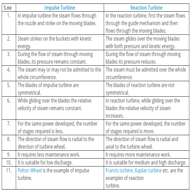
- An impulse turbine, as the name suggests, works on the principle of impulse.
- In these turbines, the head or pressure energy of water is first converted into kinetic energy by means of a nozzle or set of nozzles kept close to the runner.
- This high velocity jet produced by nozzle is allowed to impinge on the set of buckets fixed on the outer periphery of the wheel or runner. The direction of jet is changed by buckets. The change of momentum of water causes the wheel to rotate, thus produces mechanical energy.
- It should be noted that the pressure of water is atmospheric and remains constant while passing over the runner.
- Examples of important impulse turbines are Pelton wheel, Girard turbine, Turgo turbine etc.
Key Takeaways:
- In these turbines, the head or pressure energy of water is first converted into kinetic energy by means of a nozzle or set of nozzles kept close to the runner.
- It should be noted that the pressure of water is atmospheric and remains constant while passing over the runner.
Impulse turbine is fundamental kind of turbine utilized in electricity era in hydroelectricity plant. The time period impulse means unexpected pressure act to carry choice change. It denote as made from pressure and time c programming language for which it acts.
The impulse indicates the full end result of making use of pressure. Impulse turbine works at the equal principle. It is basically used at excessive heads. Today we can find out about principle, production and operating of impulse turbine.
Principle:
Impulse turbine works at the fundamental precept of impulse. When the jet of water moves on the turbine blade with complete of its speed, it generates a massive pressure which used to rotate the turbine. The pressure is relies upon at the time c programming language and speed of jet moves the blades. This turbine used to rotate the generator, which produces electric powered power.
Construction:
Blades:
The wide variety of blades is located over the rotary. They are concave in shape. The water jet moves on the blades and extrude the course of it. The pressure exerted on blades relies upon quantity of extrude in course of jet. So the blades are normally concave in shape.
Rotor:
Rotor which is likewise called wheel is located at the shaft. All blades are pined into the rotor. The pressure exerted on blades passes to the rotor which similarly rotates the shaft.
Nozzle:
A nozzle play important position of producing electricity from impulse turbine. It is a diverging nozzle which converts all stress power of water into kinetic power and paperwork the water jet. This excessive velocity water moves the blades and rotates it.
Casing:
Casing is the out of doors are which save you the turbine shape atmosphere. The important characteristic of casing is to save you discharge the water from vanes to tail race. There isn't any any extrude in stress of water from nozzle to tail race so this turbine works at atmospheric stress.
Braking nozzle:
A nozzle is supplied in contrary course of important nozzle. It is used to sluggish down or forestall the wheel.
Working:
As we mentioned impulse turbine works on primary precept of impulse. Its operating may be describe in following points.
High stress water glide shape dam (excessive head) to nozzle (low head).
This water flows thru divergent nozzle in which it’s all strain strength extrude into kinetic strength. It paperwork a water jet.
The water jet moves the blade at excessive pace which rotates the rotor.
It transfers all kinetic strength of water to the rotor, which in addition use to rotate the generator.
After shifting strength, water flows to the tail race.
This method run constantly till enough strength generates. For higher expertise watch the video given underneath on operating of impulse turbine.
Advantages & Disadvantages:
Advantage:
1. It can work at low discharge or at low go with the drift rates.
2. Impulse turbine is bendy in keeping with the burden condition. At better load multiple nozzle are used.
3. They paintings at atmospheric strain so no hassle of leakage.
4. It is straightforward to assemble.
Disadvantages:
1. Large length examine to others.
2. Efficiency decreases with time.
3. It required excessive head witch is difficult to control.
4. It is high-priced to install.
Key Takeaways:
- The impulse indicates the full end result of making use of pressure. Impulse turbine works at the equal principle.
- The pressure is relies upon at the time c programming language and speed of jet moves the blades.
- The pressure exerted on blades relies upon quantity of extrude in course of jet. So the blades are normally concave in shape.
- There isn't any extrude in stress of water from nozzle to tail race so this turbine works at atmospheric stress.
- As we mentioned impulse turbine works on primary precept of impulse. Its operating may be describe in following points.
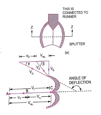
- Figure shows the shape of the veins or buckets of the Pelton wheel.
- The jet of water from the nozzle strike the bucket at the splitter which splits up the jet into two parts.
- These parts of the jet glides over the inner surfaces and comes out at the outer edge. The splitter is the inlet tip and outer edge of the bucket is the outlet tip of the bucket.
- The inlet velocity triangle is drawn at the splitter and outlet velocity triangle is drawn at the outer edge of the bucket.
H= Net head acting on the Pelton wheel
= Hg – hf
Hg = Gross head
hf = 
D* = Dia of penstock
N= Speed of the wheel in r.p.m
D= diameter of the wheel
d=diameter of the jet
Then, V1 =Velocity of jet at inlet
u = u1 = u2 =
The velocity triangle at inlet will be a straight line where
Vr1 = V1 – u1 = V1 - u
Vw1 = V1
α = 0 and θ = 0
From the velocity triangular at outlet, we have
Vr2 = Vr1 and Vw2 = Vr2 cos ∅ - u2
The force exerted by the of water in the direction of motion is given by equation
Fx = ρaV1 [Vw1 + Vw2]
As the angle β is an acute angle, positive sign should be taken
a=area of jet = πd2/4
Work done by the jet on the runner per second
= Fx × u = ρaV1 [Vw1 + Vw2]u
Power given to the runner by the jet
= 
Work done per second per unit weight of water striking
=
The energy supplied to the jet at inlet is in the form of kinetic energy and is equal to 
Kinetic energy of jet per second =

Hydraulic efficiency ηh
= 
= 
= 
Now 


= (V1 – u) 
ηh = 

= 
Key Takeaways:
- These parts of the jet glides over the inner surfaces and comes out at the outer edge. The splitter is the inlet tip and outer edge of the bucket is the outlet tip of the bucket.
- The inlet velocity triangle is drawn at the splitter and outlet velocity triangle is drawn at the outer edge of the bucket.
- The force exerted by the of water in the direction of motion is given by equation Fx = ρaV1 [Vw1 + Vw2]
The usual 3-dimensional impulse turbine version inclusive of rotor blades and manual vanes in the define applied with inside the OWC pilot plant is proven in Figure. For the rotor blade, the profile is elliptical in form at the suction facet and has a round arc form at the strain facet. There are rows of symmetrically positioned plate-kind constant manual vanes on each facets of the rotor. The camber line of the manual vanes includes a directly line and a round arc.
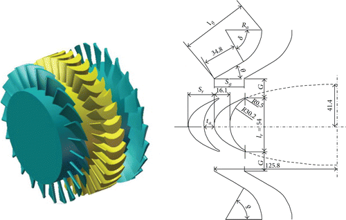
The design profile and parameters of impulse turbines used in the present paper are derived from corresponding experiments in . There are 30 rotor blades and 26 fixed guide vanes. The rotor blade pitch Sr is 26.7 mm, the width of flow path ta is 10.6 mm, the spacing G between the blade and the guide vane represents 20 mm, and the guide vane pitch Sg is 30.8 mm.
The rotor blade inlet angle is 60°, the radius of the circular arc is 30.2 mm, and the lengths of the major and minor axes of the elliptic arc on the suction side are 125.8 mm and 41.4 mm, respectively. The hub diameter is 210 mm, and the tip diameter is 298 mm.
The chord length of guide vanes is fixed at 70 mm, and the length of camber's straight line is 34.8 mm. The radius of the circular arc of guide vane Ra and the camber angle of guide vane δ vary with setting angles of the guide vane θ.
Typical characteristics of the performance of an impulse turbine in steady unidirectional flow are presented in terms of input coefficient CA, torque coefficient CT, turbine efficiency η, and flow coefficient ϕ. The definitions are given as follows
Where Δp, Q, ρa, T0 represent total pressure drop between setting camber and atmosphere, air flow rate, air density, and turbine output torque; va, rR, ω, UR, b, and z represent mean axial flow velocity, mean radius, angular velocity of the turbine, circumferential velocity at rR, blade height, and number of rotor blades, respectively.
Important parameters which are varied during a test on a turbine
1) Speed (N)
2) Head (H)
3) Discharge (Q)
4) Power (P)
5) Overall efficiency (η0)
6) Gate opening
- Out of the above 6 parameters, three parameters namely speed head and discharge are independent parameters.
- Out of the three independent parameters (N,H,Q) one of the parameter is kept constant and the variation of the other four parameters with respect to anyone of the remaining two independent variables are plotted and various are obtained.
- These are called characteristic curves.
- The following are the important characteristic curves of a turbine.
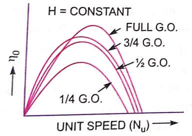
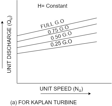
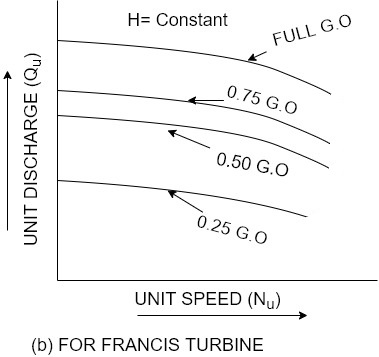
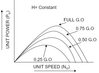
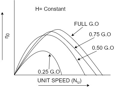
Constant head curves
- These curves are obtained by keeping head constant and a constant gate opening on the turbine.
- The speed of the turbine is varied by changing load on the turbine.
- For each value of speed, the corresponding values of the power(P), discharge(Q) are obtained.


For a Pelton wheel
For reaction turbines
- Then the overall.
0f
Or each value of the speed is calculated.
- From these reading the values of unit speed
Nu
Unit power
Pu and unit discharge Qu
a determined.
Taking Nu as abscissa, the values of
Qw, Pu, P and 0 are plotted as shown in figure by changing the gate opening, the values of Qw, Pu, 0 and Nu are determined and taking Nu as abscissa.
- Figure a shows the main characteristic curves for Pelton wheel and figure b shows the main characteristic curves for reaction turbines.
Operating characteristic curves for constant speed curves
Operating characteristic curves are plotted when speed on the turbine is constant.
In case of turbines, the head is generally constant.
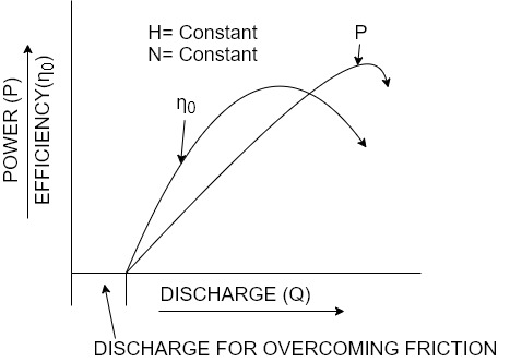
- For operating characteristics N and H are constant and hence the variation of power and efficiency with respect to discharge Q are plotted.
- The power curve for turbines shall not pass through the origin because certain amount of discharge is needed to produce power to overcome initial friction.
- Hence the power and efficiency curves will be slightly away from the origin on the x-axis, as to overcome initial friction certain amount of discharge will be required.
- Shows the variation of power and efficiency with respect to discharge.
Constant efficiency curves or Muschel curves or iso-efficiency curves
These curves are obtained from speed versus efficiency and speed versus discharge curves for different gate opening.
For a given efficiency from the
Nuvs η0
Curves, there are two speeds.
From
Nuvs Qu
Curves, corresponding to two values of speeds there are two values of discharge.
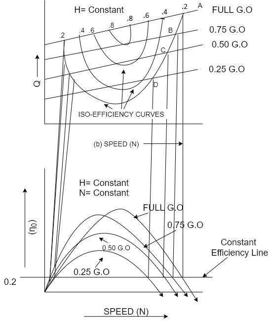
- Hence for a given efficiency there are two values of discharge for the particular gate opening.
- This means for a given efficiency there are two values of speeds and two values of discharge for a given gate opening.
- If the efficiency is maximum there is only one value.
- These two values of speed and two values of discharge corresponding to particular gate opening are plotted as shown in figure.
- The procedure is repeated for different gate opening and the curves Q vs N are plotted.
- The points having the same efficiency are called iso- efficiency curves.
- These curves are helpful for determining the zone of constant efficiency and for predicting the performance of the turbine at various efficiencies.
- For plotting the iso-efficiency curves horizontal lines representing the same efficiency are drawn on the η0 speed curves.
- The points at which these lines cut the efficiency curves at various gate openings are transferred to the corresponding Q~ speed curves.
- The points having the same efficiency are less then joined by a smooth curve.
- These smooth curves represent the ISO efficiency curve.
Key Takeaways:
- For operating characteristics N and H are constant and hence the variation of power and efficiency with respect to discharge Q are plotted.
- These curves are obtained from speed versus efficiency and speed versus discharge curves for different gate opening.
- This means for a given efficiency there are two values of speeds and two values of discharge for a given gate opening.
- For plotting the iso-efficiency curves horizontal lines representing the same efficiency are drawn on the η0 speed curves.
- The governing of turbine is defined as operation by which the speed of the turbine is kept constant under all conditions of working.
- It is done automatically by means of governor, which regulates the rate of flow through the turbines according to the changing load conditions on the turbine.
- Governing of a turbine is necessary as a turbine is directly coupled to an electric generator which is required to run at constant speed under all fluctuating load conditions. This is only possible when the speed of the turbine is constant.
- One of the common types of governor which is predominantly used with modern turbines is oil pressure governor.
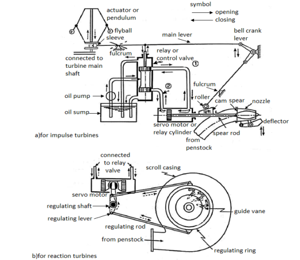
As shown in figure its component parts are as follows:
1) Servo motor also known as relay cylinder.
2) Relay valve known as control valve.
3) Actuator
4) Oil sump
5) Oil pump which is driven by belt connected to turbine main shaft.
6) A system of oil supply pipes connecting the oil sump with servo motor.
The working of the governor is explained below.
- When the load on the governor drops the speed of turbine increases.
- Now since the actuator driven by the turbine main shaft due to increase in the speed the balls move outward resulting in upward movement of the sleeve shown in figure.
- As this sleeve moves up the left-hand end of the main lever is raised, which causes the bell crank lever to move downward and simultaneously pushes the piston of the control valve in its cylinder.
- In case of a Pelton turbine the bell crank lever brings the deflector in a front of the jet thereby diverting portion of the jet away from the buckets.
- On the other hand in the case of reaction turbine such as Francis or Kaplan turbine relief valve shown in figure is provided.
- A relief valve consists of a spear which under normal condition of operation of turbine is held by oil or water under pressure in such a position that it keeps the opening of the bypass from the spiral casing to the tail race closed.
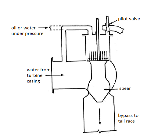
- The downward motion of the bell crank lever opens the pilot valve of the pressure chamber so that the pressure on the spear is reduced, thereby permitting spear to be lifted up and allowing a portion of water to flow directly from the spiral casing to the tail race through the bypass without striking the turbine runner.
- Thus both these devices deflector and relief valves have similar functions to perform.
- These eliminate the necessity of rapid closure of the nozzle opening or guide vanes, at the same time the quantity of water striking the runner is reduced.
- With downward motion of the piston of the control valve the passage for pipeline 2 opens & oil under pressure is admitted from the control valves cylinder to the servo motor on the left side of the piston.
- The servo motor piston therefore moves to right.
- In the case of Pelton wheel the servo motor piston being connected to the spear rod, thus causes the spear to move forward.
- The forward motion of the spear reduces the area of nozzle and thus decreases the rate of flow.
- However, in the case of a reaction turbine the forward motion of servo motor piston is transmitted to the regulating ring as shown in figure (b) which causes oil the guide vanes to move simultaneously in one direction and thus the area of flow passage between the adjacent guide vanes is reduced and rate of flow of water striking the runner is also reduce.
- When the load on the generator increases, the speed of the turbine runner decreases.
- Due to this the balls move inward resulting in in the downward movement of the sleeve.
- The left hand end of the main lever is lowered which puts the piston of the control valve up in the cylinder, with the upward motion of the piston pipeline 1 opens and oil under pressure rushes from the control valve cylinder to the servo motor on the right side of the piston.
- The servo motor piston then moves to the left.
- Thus increase the area of nozzle outlet or passage between the adjacent guide vanes there by allowing a large quantity of water to strike the runner and the normal speed for the turbine runner is thus restored.
Key Takeaways:
- When the load on the governor drops the speed of turbine increases.
- Now since the actuator driven by the turbine main shaft due to increase in the speed the balls move outward resulting in upward movement of the sleeve shown in figure.
- On the other hand in the case of reaction turbine such as Francis or Kaplan turbine relief valve shown in figure is provided.
- Thus both these devices deflector and relief valves have similar functions to perform.
- We have already discussed that in case of impulse turbines the total head available is first converted into velocity head in nozzles before the water enters the runner.
- Whereas, in case of reaction turbines only a part of total available head is converted into velocity head while passing over the fixed guide vanes before it enters the runner.
- Therefore, in reaction turbine the water enters the runner under pressure having some velocity head: While the water passes over the runner, its pressure is gradually converted into velocity head until its pressure is reduced to atmospheric pressure along with the change in kinetic energy based on its absolute velocity.
- The reaction due to pressure difference and the impulse action is responsible for rotation of runner and producing the mechanical work.
- Since the water flows under pressure over the runner, above atmospheric it is necessary that the runner must run full of water.
- The water from runner is discharged into tail race through a closed tube of gradually increasing cross-sectional area called a draft tube.
- Also, the cross-sectional of flow through the passages of runner must gradually increase to accommodate the change in static pressure of water.
- The reaction turbines are suitable for low and medium heads ranging from 30 m to 250 m of head some of the important reaction turbines are Fourneyron, Francis, Kaplan and propeller turbines.
Key Takeaways:
We have already discussed that in case of impulse turbines the total head available is first converted into velocity head in nozzles before the water enters the runner. Whereas, in case of reaction turbines only a part of total available head is converted into velocity head while passing over the fixed guide vanes before it enters the runner.
Types of Reaction Turbine are
1. Radial Flow Turbines
A radial turbine is a turbine wherein the waft of the running fluid is radial to the shaft. The distinction among axial and radial mills is composed with inside the manner the fluid flows thru the components (compressor and turbine). Whereas for an axial turbine the rotor is 'impacted' through the fluid waft, for a radial turbine, the waft is easily oriented perpendicular to the rotation axis, and it drives the turbine with inside the equal manner water drives a watermill.
The end result is much less mechanical stress (and much less thermal stress, in case of warm running fluids) which allows a radial turbine to be simpler, extra robust, and extra efficient (in a comparable strength range) while in comparison to axial mills.
When it involves excessive strength ranges (above five MW) the radial turbine is now not competitive (because of its heavy and high-priced rotor) and the performance will become much like that of the axial mills.
Inward Flow Turbines
Outward Flow Turbines
2. Axial Flow Turbines
Steam mills perform to transform the thermal electricity to be had with inside the steam into mechanical electricity. They are used for strength era in thermal electricity flora.
Such electricity flora make use of herbal fuelling, fossil fuel, coal, or nuclear fuel. A steam turbine is a warmness engine that obtains plenty of its development in thermodynamic performance the use of more than one stages, which ends up in a better situation to the right reversible growth procedure. Because the turbine creates rotating motion, it's miles especially appropriate for riding an electrical generator. For example, in 2014, approximately 85% of all strength within side the U.S became generated via way of means of the usage of steam mills. A rapid generator is a steam turbine this is connected to an electric powered generator. The improvement of steam mills became years earlier than the fuel line mills. Therefore, the layout of the axial waft fuelling mills is the end result of the increase of steam turbine technology.
- Kaplan turbine
- Propeller turbines
3. Mixed Flow Turbines
In a radial turbine, the fluid enters a tangential route -alongside a directly from the pinnacle of a circle to the left or right- and spirals like while the water discharges a toilet. Imagine that the water spiral turns fan blades within side the identical route because the water. This will be the fundamental idea of a radial turbine. The radial turbine has a performance of approximately 80%.
Again, remember the rest room example; while you flush the rest room, the water out of doors the bowl once in a while does now no longer flow into flawlessly with the relaxation of the water.
This part of water is referred to as the secondary float of the rest room water. The greater the secondary water is within side the float, the much less water contributes to turning the fan.
Therefore, the performance decreases. When each of those designs are combined, the performance rises to approximately 85% to 90 cause, in a combined float turbine, the fluid enters radially, the secondary float is minimized, and the performance of the axial turbine component is maximized with a compelled fluid float.
It might not appear like a considerable growth in performance, however on a big commercial scale that expenses hundreds of thousands of bucks in energy, even a small growth in performance can keep an excellent deal.
- Degree of reaction is defined as the ratio of pressure drop in the runner to hydraulic work done on the runner.
- It is denoted by .
- Thus if
p1 and p2 are the pressure at the inlet and outlet of the runner then,
ρ = 
If Vw2 = 0
ρ = 
- The draft tube is pipe of gradually increasing area which connects the outlet of the runner to the tail race.
- It is used for discharging water from the exit of the turbine to the tail race.
- Draft has following function to perform
- It permits negative head to be established at the outlet of the runner and thereby increase the net head on the turbine.
- The turbine may be placed above the tail race without any loss of net head and hence turbine may be inspected properly.
- It converts a large portion of kinetic energy (
 at the outlet of turbine into useful pressure energy.
 - Hence by using draft tube the net head on the turbine increases.
- The turbine develops more power and also the efficiency of turbine increases.
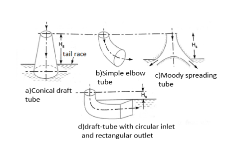
Types of draft tubes
The following are the important types of draft tubes which are commonly used
1) Conical draft tube
- In this type of draft tube, the flow path is straight and divergent. This draft tube is fabricated with mild steel plates.
- It is tapered in shape and the outlet diameter is larger than inlet diameter of this draft tube.
- The tapered angle of draft tube should not be too large as it will cause the separation of flow from the wall of draft tube.
- This angle should not be too small also as it will require a longer draft tube which causes a significant loss of kinetic energy. So the taper angle is always nearly 10 degrees.
2) Simple elbow tubes
- In Simple Elbow draft tube, the tube is of elbow shaped. It is mainly used in Kaplan turbine.
- In this type of draft tube, the cross section area remains same throughout the length of draft tube.
- The inlet and outlet of the draft tube is circular shaped.
- This draft tube is generally used at places of low head and the turbine is to be placed close to the tail race.
- It helps to cut down the cost of excavation and the exit diameter should be as large as possible to recover kinetic energy at outlet of runner.
3) Moody spreading tubes
- In this type of draft tube, the outlet of the daft tube is divided into two parts.
- It is similar to conical draft tube and is provided with the central core part which divide the outlet into two parts.
- There is one inlet and two outlets of this draft tube.
- This type of draft tube is mainly used to reduce the swirling action of water.
- It is used in vertical shaft turbine.
- Efficiency of this type of draft tube is nearly 88 percent.
4) Elbow draft tubes with circular inlet and rectangular outlet
- Elbow draft tube with varying cross section is an improvement of simple elbow draft.
- In this type of draft tube, the inlet is circular and the outlet is of rectangular shape.
- The horizontal part of the draft tube is generally inclined upwards to prevent entry of the air from the exit end.
- The cross-section area of this type of draft tube changes from inlet to outlet. Outlet of this draft tube is always below the tail race.
- It is generally used in Kaplan Turbine and efficiency of this type of draft tube is about 70 percent.
Draft tube theory: -
Consider a conical draft tube as shown in figure.
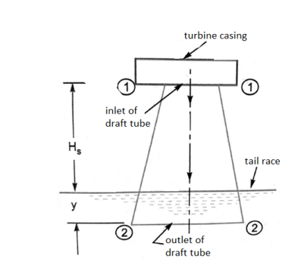
Let, Hs = Vertical height of draft tube above the tail race
y = distance of bottom of draft tube from tail race
Applying Bernoulli's equation to inlet (section 1-1) and outlet (section 2-2) of the draft tube and taking section 2-2 as the datum line we get

Where  loss of energy between section 1-1 and 2-2.
But,  atmospheric pressure head + y
= 
Substituting this value of  in equation (i) we get


In above equation,  is less than atmospheric pressure.
Efficiency of draft tube
The efficiency of a draft tube is defined as the ratio of actual conversion of kinetic head into pressure head in the draft tube to the kinetic head at the inlet of the draft tube.
Mathematically,
ηd = 
V1 = Velocity of water at inlet of draft tube
V2 =Velocity of water at outlet of draft tube and,
hf =Loss of head in the draft tube
Theoretical conversion of kinetic head into pressure head in draft tube = 
Actual conversion of kinetic head into pressure head=(  - hf
- hf
= 
Key Takeaways:
- The turbine may be placed above the tail race without any loss of net head and hence turbine may be inspected properly.
- It is tapered in shape and the outlet diameter is larger than inlet diameter of this draft tube.
- In this type of draft tube, the cross section area remains same throughout the length of draft tube.
- It is similar to conical draft tube and is provided with the central core part which divide the outlet into two parts.
- The cross-section area of this type of draft tube changes from inlet to outlet. Outlet of this draft tube is always below the tail race.
- When the pressure in any part of the flow passage reaches the vapour pressure of the flowing liquid, it starts vaporizing and small bubbles of vapour form in large numbers.
- These bubbles are carried along by the flow and on reaching the high pressure zones these bubbles suddenly collapse as the vapour condenses to liquid again.
- Due to sudden collapsing of the bubbles cavities are formed.
- The surrounding liquid rushes in to them.
- The liquid moving from all directions collides at the centre of the cavity, thus giving rise to very high local pressure.
- Any solid surface in the vicinity is also subjected these intense pressure.
- The alternate formation and collapse of vapour bubbles may cause serve damage to the surface which ultimately fails by fatigue and the surface becomes badly scored and pitted.
- This phenomenon is known as cavitation.
Precautions against cavitation
The following precautions should be taken against cavitation
- The pressure of the flowing liquid in any part of the hydraulic system should not be allowed to fall below its vapour pressure. If the flowing liquid is water, then the absolute pressure head should not be below 2.5 m of water.
- The special materials or coatings such as aluminium bronze and stainless steel which are cavitation resistant materials should be used.
Key takeaways:
- These bubbles are carried along by the flow and on reaching the high pressure zones these bubbles suddenly collapse as the vapour condenses to liquid again.
- Any solid surface in the vicinity is also subjected these intense pressure.
It is one of the type of reaction turbine. The Francis turbine especially classified based on the discharge and head.
1. Medium Head:
The name itself indicates that the turbine have medium head than other turbine.
2. Medium Discharge:
This kind of turbines are comes under Francis turbine. Due to its discharge capacity and working it is classified as medium discharge turbines.
Francis turbines
- Figure shows a Francis turbine which is a mixed flow type reaction turbine.
- The water from penstock enters a scroll casing which completely surrounds the runner.
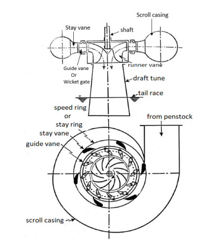
- The purpose of the casing is to provide an even distribution of water around the circumference of the turbine runner, maintaining an approximately constant velocity for the water so distributed.
- The casing is made of a cast steel, plate steel, concrete and steel depending upon the pressure to which it is subjected.
- From the scroll casing the water passes through a speed ring held together by series of fixed vanes called stray vanes.
- The speed wing has two functions to perform.
- It directs the water from the scroll casing to the guide vanes.
- Further it resists the load imposed upon it by internal pressure of water and the weight of the turbine and the electrical generator and transmits the same to the foundation.
- From the speed ring the water passes through a series of guide vanes provided all around the periphery of the turbine runner.
- The function of guide vanes is to regulate the quantity of water supply to the runner and to direct water onto the runner at an angle approximate to the design.
- Guide vanes can turn about their stems. So as to alter the width of the passage between them.
- The runner of Francis turbine consists of series of curved veins evenly arranged around the circumference in the annular space between two plates.
- The vanes are so shaped that water enters the runner at the outer periphery and leaves it axially at the lower periphery.
- The change in the direction of flow of water from radial to axial as it passes through the runner, produces a circumferential force on the runner which makes the runner to rotate and thus contribute to useful output of the runner.
- The torque produced by the runner is transmitted to the generator through the shaft which is usually connected to the generator shaft by a bolted flange connection.
- The water after passing through runner flows to the tail race through to a draft tube.
Key Takeaways:
- The purpose of the casing is to provide an even distribution of water around the circumference of the turbine runner, maintaining an approximately constant velocity for the water so distributed.
- Further it resists the load imposed upon it by internal pressure of water and the weight of the turbine and the electrical generator and transmits the same to the foundation.
- The runner of Francis turbine consists of series of curved veins evenly arranged around the circumference in the annular space between two plates.
- Francis is an inward go with the drift response turbine that mixes radial an axial go with the drift. Electric mills frequently used have an electricity output that tiers from 10 KW to 800 MW.
- The velocity variety of the turbine is from seventy five to one thousand rpm.
- The feasibility observe of turbine production in Nepal has proven that Nepalese producer has an amiable destiny with inside the subject of Francis turbine production.
- It is comprehensible that the mills with inside the huge hydropower flora want a licensed company, prepared with layout know-how and technological advancement.
- Various forms of production technique utilized in Francis Turbine production became cited and a listing of them which may be without difficulty applied in Nepal is taken in to consideration.
- On to the subsequent step, all the producing records like production tolerances, time, strength, hardness, roughness, price, etc. had been cited.
- A CSV document became generated to keep them and records augmentation became used to generate numerous nodes to educate our choice tree version that's then observed with the aid of using choice tree analysis.
- Based at the records, an appropriate production technique in addition to different options may be acquired which may be utilized in production of Francis Runner.
- Francis Turbine is a mixture of each impulse and response turbine, wherein the blades rotate the usage of each response and impulse pressure of water flowing thru them generating strength extra efficiently.
- Francis turbine is used for the manufacturing of strength in hydro energy stations. Majorly there are 2 mills float styles on which they work, particularly radial and axial float concepts.
Key Takeaways:
- Francis is an inward go with the drift response turbine that mixes radial an axial go with the drift. Electric mills frequently used have an electricity output that tiers from 10 KW to 800 MW.
- On to the subsequent step, all the producing records like production tolerances, time, strength, hardness, roughness, price, etc. had been cited.
- Based at the records, an appropriate production technique in addition to different options may be acquired which may be utilized in production of Francis Runner.
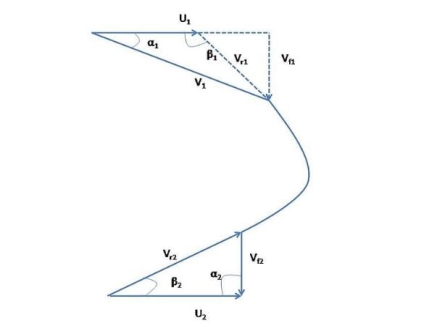
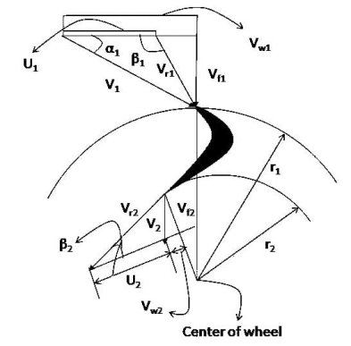
The Velocity Diagram of Francis Turbine is proven below. This pace diagram virtually indicates that during perfect cases, the whirl aspect of outlet pace is 0 i.e at the hole the go with the drift is absolutely axial.
Blade Efficiency:
Usually the flow velocity (velocity perpendicular to the tangential direction) remains constant throughout, i.e. Vf1 = Vf2 and is equal to that at the inlet to the draft tube. Using the Euler turbine equation, E/m = e = Vw1 U1, where e is the energy transfer to the rotor per unit mass of the fluid. From the inlet velocity triangle.
Vw1 = Vf1 cot α1
And
U1 = Vf1 (cot α1 + cot β1).
Therefore,
e = V2f1 cot α1 (cot α1 + cot β1).
The loss of kinetic energy per unit mass becomes V2f2 /2.
Therefore, neglecting friction, the blade efficiency becomes
ηb =
i.e.,
ηb = 
Degree of Reaction:
Degree of reaction can be defined as the ratio of pressure energy change in the blades to total energy change of the fluid.[2] This means that it is a ratio indicating the fraction of total change in fluid pressure energy occurring in the blades of the turbine. For example, if the degree of reaction is given as 50%, that means that half of the total energy change of the fluid is taking place in the rotor blades and the other half is occurring in the stator blades. If the degree of reaction is zero it means that the energy changes due to the rotorblades is zero, leading to a different turbine design called the Pelton Turbine.

The second equality above holds, since discharge is radial in a Francis turbine. Now, putting in the value of ‘e’ from above and using

R = 1 - 
Key Takeaways:
- The Velocity Diagram of Francis Turbine is proven below. This pace diagram virtually indicates that during perfect cases, the whirl aspect of outlet pace is 0 i.e at the hole the go with the drift is absolutely axial.
Every hydroelectric electricity plant (HEPP) calls for a custom layout for a turbine that allows you to function at most performance primarily based totally on its head and glide charge. The rotational velocity of the turbine, runner geometry, head and glide charge have an effect on the layout.
Flow behaviour, glide angles, head losses, strain distribution and cavitation traits are computed, analysed and as compared for the designed turbine runners. The fashionable effects of those parameters at the turbine overall performance are summarized and empirical formulations are derived for runner overall performance characterization.
Since each electricity plant wishes a completely unique turbine layout, the venture is to attain generalizations and generalized formulations primarily based totally on numerous instances which might be relevant to an entire variety of generators.
The runner layout system is stricken by numerous parameters due to the complexity of its geometry, in addition to third-dimensional rotational nature of the glide.
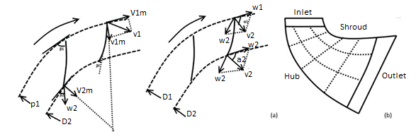
The maximum crucial parameters are the rotational velocity of the turbine n, the manual vane peak boo, the runner inlet and outlet diameters D1 and D2, the alpha perspective α, the blade beta perspective β, the glide perspective beta βf, and the theta perspective θ (Figure 1). These parameters are changed to make certain that the electricity, performance and hydraulic overall performance of the machine are maximized.
A parametric examine turned into finished to decide the consequences of the layout parameters on overall performance. Table 1 suggests the parameters and their ranges.
In this figure 1, V1u is tangential velocity component, V1m is meridional velocity component, V1 and V2 are inlet and outlet absolute velocity components, respectively. u1 and u2 are peripheral inlet and outlet velocity components, respectively. ω1 and ω2 are relative speed at the inlet and outlet. D1d denotes runner inlet diameter and D2d denotes runner outlet diameter.
The torque on the shaft is equal to the change in angular momentum of the water flow. Equation (1) below is obtained by using the angular momentum equation for the inlet to the outlet of the runner. The sum of the moments of external forces about the axis of rotation is as follows:
 (1)
(1)
Figure 2 presents the velocities at the leading and trailing edges of the runner blades. Torque is only generated when runner blades generate circulation in the runner. The generated power can be calculated using the moment equation and angular velocity of the runner N = Mω = ρg H Qn (2)where H is the head of the turbine and is the hydraulic efficiency. The main energy equation of turbines (Euler equation) is obtained substituting for M in Equation (2):
Hη = 1/ g ( u1 v1 cos α1 – u2 v2 cos α2).(3)
Figure. Velocities at the edges of the runner blades.
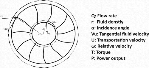
Equation (3) can be written as follows using the expressions for circulation:
Hη =  (4)
(4)
Hydraulic energy is related to the mechanical energy which is absorbed by the runner as shown in Equation (3). The angles at which water enters and exits the runner are also important parameters that affect hydraulic performance. The position of the guide vane determines the angle of the water inlet of the runner; therefore, the guide vane angle is a major parameter as well. Changing the guide vane angle changes the efficiency.
The flow rate Q, rotational speed n and head H are the preset operating conditions of the turbine. It is possible to determine the components of the velocity parallelograms using these known parameters and the dimensions of the runner (Figure 1(a)). In Figure 1(a), D1d is the inlet of the blade edge and D2d is the outlet of the blade edge.
The transportation velocity is expressed as u =  , (5)where n is the rotational speed and D is the inlet or outlet of the blade edge. The meridional component Vm can be calculated using continuity equation and is defined as:
υm =  , (6)where b0 is the height of the inlet opening of the runner. The peripheral component V1u is calculated from constant circulation condition and is equal to υ1u = υ0u
  (7) Finally, V1 and V2 can be found by calculating the meridional and peripheral components as follows: υi =
  (8)
(8)
Key Takeaways:
- Since each electricity plant wishes a completely unique turbine layout, the venture is to attain generalizations and generalized formulations primarily based totally on numerous instances which might be relevant to an entire variety of generators.
- A parametric examine turned into finished to decide the consequences of the layout parameters on overall performance
- Hydraulic energy is related to the mechanical energy which is absorbed by the runner as shown in Equation (3). The angles at which water enters and exits the runner are also important parameters that affect hydraulic performance. The position of the guide vane determines the angle of the water inlet of the runner; therefore, the guide vane angle is a major parameter as well. Changing the guide vane angle changes the efficiency.
The Francis turbine is a response turbine, wherein the fluid modifications stress because it movements thru the turbine, giving up its energy. The turbine is positioned among the excessive stress water supply and the low stress water go out.
The inlet of turbine is in spiral form. The manual vanes direct the water tangentially to the turbine wheel that's called a runner. This radial float of water acts at the runner's vanes, inflicting the runner to spin.
The manual vanes can be adjustable to permit green turbine operation for a variety of water float conditions. At the factor of go out, the water leaves without a swirl and little or no kinetic or capability energy.
The form of the turbine's go out tube facilitates to slow down the float of water and get better the stress.
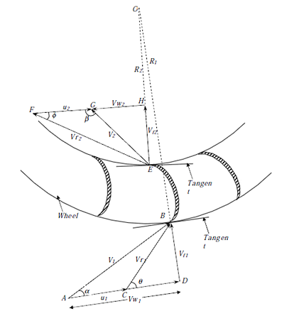
Let,
R1 = Radius of wheel at inlet of the vane
R2 = Radius of wheel at outlet of the vane
ω = Angular speed of the wheel
Tangential speed of the vane at inlet = u1 = R1
Tangential speed of the vane at outlet = u2 = R2
The velocity triangles at inlet and outlet are drawn as shown in figure. α and β are the angles between the absolute velocities of jet and vane at inlet and outlet respectively. θ and ψ are vane angles at inlet and outlet respectively.
The mass of water striking a series of vanes per second = ρ a V1
Where, a is the area of jet or flow and V1 is the velocity of flow at inlet.
The momentum of water striking a series of vanes per second at inlet is given by the product of mass of water striking per second and the component of velocity of flow at inlet = ρ a V1× Vω1 , where Vω1 is the velocity component of flow at inlet along tangential direction. Similarly momentum of water striking a series of vanes per second at outlet is given by ρ a V1× Vω1 , where - Vω1 is the velocity component of flow at inlet along tangential direction and the -ve sign is because the velocity component is acting in the opposite direction. Now angular momentum per second at inlet is given by the product of momentum of water at inlet and its radial distance = ρ a V1× Vω1 ×R1 and angular momentum per second at inlet = - ρ a V1× Vω2 ×R2
Torque exerted by water on the wheel is given by impulse momentum theorem as the rate of change of angular momentum
T = ρ a V1× Vω1 ×R1 – ( - ρ a V1× Vω2 ×R2)
T = ρ a V1( Vω1 ×R1 + Vω2 ×R2)
Work done per second on the wheel = Torque x Angular velocity
= T. ω
= ρ a V1( Vω1 ×R1 + Vω2 ×R2)× ω
= ρ a V1( Vω1 ×R1 + Vω2 ×R2× ω)
As u1 = ω R1 and u2 = ω R2
We can simplify the above equation as
W D/s = ρ a V1( Vω1 u1 + Vω2 u2)
In the above case, always the velocity of whirl at outlet is given by both magnitude and direction as
Vω2 = (Vr2 cos ϕ – u2)
If the discharge is radial at outlet, then Vω2 = 0 and
Hence the equation reduces to,
W D/s = ρ a u1 V1 Vω1
K E/s = ½ ρ a V13
Efficiency of the reaction turbine is given by,
η = 
Note: The value of the velocity of whirl at outlet is to be substituted as
 along with its sign.
= 
Speed ratio = 
Where, H is the Head on turbine, it varies from 0.6 to 0.9.
Flow ratio = 
Where,  is the velocity of flow at inlet, it varies from 0.15 to 0.3.
Discharge flowing through the reaction turbine is given by
Q =  =
= 
Where, D1 and D2 are the diameter of the runner at inlet and outlet. B1 and B2 are the width of the runner at inlet and outlet. Vf1 and Vf2 velocity at inlet and outlet. If the thickness (t) of the vane is to be considered, then
The area through which flow takes place is given by
= (π D1 – n t)
Where, n is the number of vanes mounted on the runner.
Discharge flowing through the reaction turbine is given by
Q = (π D1 – nt) B1 Vf 1 = (πD2 – n t) B2 Vf 2
The head (H) on the turbine is given by
= 
u1 =  and u2 =
Hydraulic efficiency is
= =  =
= 
If the discharge at the exit is radial then , 
Hence hydraulic efficiency is

Key Takeaways:
- The Francis turbine is a response turbine, wherein the fluid modifications stress because it movements thru the turbine, giving up its energy. The turbine is positioned among the excessive stress water supply and the low stress water go out.
- The velocity triangles at inlet and outlet are drawn as shown in figure. α And β are the angles between the absolute velocities of jet and vane at inlet and outlet respectively. θ And ψ are vane angles at inlet and outlet respectively.
- Torque exerted by water on the wheel is given by impulse momentum theorem as the rate of change of angular momentum
T = ρ a V1 × Vω1 ×R1 – ( - ρ a V1 × Vω2 ×R2 )
T = ρ a V1 ( Vω1 R1 + Vω2 ×R2 )
The manual blades of the Francis turbine are pivoted and linked with the aid of using levers and hyperlinks to the regulating ring. The regulating ring is connected with regulating rods linked to the regulating lever. Thus regulating lever, in turn, is hooked up with regulating shaft that is operated with the aid of using the piston of servomotor.
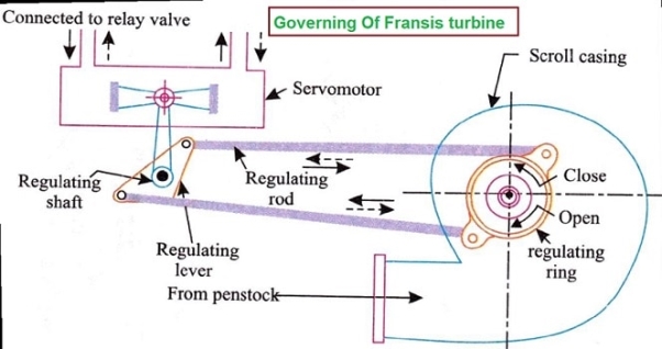
When the burden at the turbine decreases, velocity has a tendency to increase, which actions fly balls upwards and consequently increases sleeves. The predominant lever on the alternative facet of the fulcrum pushes down the manage valve rod and opens port V1.
Oil beneath Neath strain enters the servomotor from left and pushes the piston to actions toward right. When the piston of the servomotor actions toward the right, regulating the hoop is turned around to lower the passage among the manual vanes with the aid of using converting manual vane angles.
Thus the amount of water attaining the runner blades reduces and velocity decreases to the regular velocity.
Sudden discount in passage among the manual blades might also additionally purpose a water hammer which may be avoided with the aid of using offering a comfort valve close to the turbine which diverts the water without delay to the tailrace. Thus it features just like that of jet deflector as with inside the Pelton wheel. Thus double law is likewise nicely done in Francis turbine.
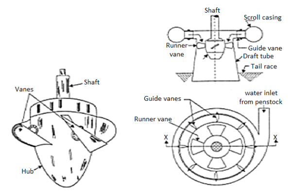
The propeller turbine is a kind of inward waft response turbine with a propeller-formed runner, which may be visible in ships and submarines. It is ready with both constant and adjustable blades. In the propeller turbine, the water waft is regulated with the aid of using adjustable manual vanes (or wicket gates). The vanes flow the water into the runner to switch its strength to the blades.
Different kinds of propeller generators to be had with inside the hydraulic electricity industries are bulb turbine, Straflo turbine, tube turbine, and Kaplan turbine.
Propeller Turbine Working Principle
Most response generators are propeller kind. The propeller turbine runner usually has 3 to 6 blades, to which water moves constantly at a regular rate. The blades pitch can be constant or adjustable. The fundamental additives of a propeller turbine are the runner, a scroll case, wicket gates, and the draft tube.
The fundamental a part of the runner is the propeller together with the rotating hub and blades to hold the fluid capability and kinetic strength to the shaft connected to the turbine. Propellers may be labelled primarily based totally on extraordinary methods, which include the variety of blades or blade pitch.
You can go to this hyperlink to analyse greater approximately the propeller. The waft route is axial for maximum propeller generators, parallel to the axis of rotation. They are consequently labelled as mid-waft generators. Early traits used propeller turbine gadgets with vertical shafts. More current traits make use of a horizontal shaft.
The blade of a propeller turbine may be rigidly connected to the hub, referred to as fured-blade runners. The runner blades also can be constructed adjustable in order that the turbine can paintings greater correctly in a huge variety of waft conditions.
A propeller-kind turbine that has adjustable blades and stuck gates is every so often referred to as a semi-Kaplan. The automated coordination of runner blades motion and adjusting the wicket gates role reasons most appropriate hydraulic overall performance, making such gadgets greater green for variable waft fees and occasional head applications.
Propeller generators are designed for heads from 1.five to 60 meters however are normally used for heads much less than 30 meters. In a hard and fast blade propeller turbine, the variety of waft operation is higher to be among seventy five and 100% of quality performance point (BEP) waft.
Kaplan generators may also perform among 25 and 125% of the quality performance discharge rate. The head variety for the good enough overall performance of the turbine is from 20 to 140% of the layout head
Velocity Diagrams:
Propeller turbine is axial glide response turbine, usually used for low head. The fundamental propeller turbine is composed of a propeller turbine, just like a ship’s propeller, outfitted inner a continuation of the penstock tube.
The fluid in the propeller turbine converts via a proper attitude into the axial route among the manual vanes and the runners and then paintings at the runners. The propeller runner has constantly 4 or six blades just like a ship’s propeller.
The glide drawing near the runner blades is a loose vortex this is whirl pace inversely proportional to radius, while the rate of the blades is at once proportional to radius.
To create for the various among the fluid pace and the blade pace because the radius increases, the blade are twisted because the attitude with the axis of the rotor (or) shaft being greater on the tip than on the hub
Key Takeaways:
- Most response generators are propeller kind. The propeller turbine runner usually has 3 to 6 blades, to which water moves constantly at a regular rate. The blades pitch can be constant or adjustable. The fundamental additives of a propeller turbine are the runner, a scroll case, wicket gates, and the draft tube
- Kaplan generators may also perform among 25 and 125% of the quality performance discharge rate. The head variety for the good enough overall performance of the turbine is from 20 to 140% of the layout head
- Propeller turbine is axial glide response turbine, usually used for low head. The fundamental propeller turbine is composed of a propeller turbine, just like a ship’s propeller, outfitted inner a continuation of the penstock tube.
Kaplan turbines
- It is an axial flow turbine, which is suitable for relative low heads and hence requires a large quantity of water to develop large amount of power.
- As shown in figure the main component of Kaplan turbine are scroll casing, stay ring arrangement of guide vanes and the draft tube.
- Scroll Casing
It's a spiral-shaped casing with a smaller cross section area. Water from the penstocks enters the scroll casing, then runs axially through the runner into the guide vanes, where it spins 90 degrees. It shields the turbine's runner, runner blades, guiding vanes, and other internal components from external damage.
- Guide Vane Mechanism
It is the only portion of the turbine that controls the opening and closing of the blades in response to the demand for power. When more power is required, it opens wider to allow more water to hit the rotor's blades, and when less power is required, it closes to stop the flow of water. The turbine will not run efficiently if the guide vanes are missing.
- Draft Tube
The pressure at the exit of a Reaction Turbine's runner is usually lower than air pressure. The water near the exit cannot be released directly into the tail race. Water is discharged from the turbine exit to the tail race through a tube or pipe with a gradually increasing area. Draft Tube is the term given to this expanding tube. The tube is attached to the runner's output on one end and submerged below the water level in the tail-race on the other
- Between guide vanes and the runner the water in Kaplan turbine turns through right angle into axial direction and then passes through the runner.
- The runner of a Kaplan turbine has 4 or 6 blades.
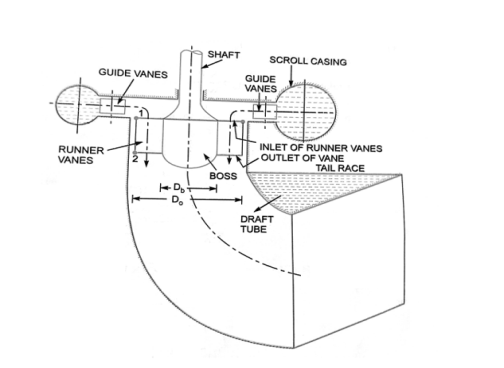
- The blades attached to a hub for boss are so shaped that water flows axially to the runner.
- Ordinarily the runner blades of propeller turbines are fixed, but the Kaplan turbine runner blades can be turned about their own axis, so that their angle of inclination maybe adjust while the turbine is in motion.
- The adjustment of the runner blades is usually carried out automatically by means of servomotor operating inside the hollow coupling of turbine and generator shaft.
- When the vanes are fixed to the hub and are not adjustable, the turbine is known as propeller turbine.
Working
The water coming from the pen-stock is made to enter the scroll casing. The scroll casing is made in the required shape that the flow pressure is not lost. The guide vanes direct the water to the runner blades. The vanes are adjustable and can adjust itself according to the requirement of flow rate. The water takes a 90 degree turn, so the direction of the water is axial to that of runner blades.
As the water strikes, the runner blades begin to revolve due to the water's reaction force. The runner blades twist along their length to maintain an optimal angle of attack for all cross sections of the blades, resulting in increased efficiency. The water enters the draft tube from the runner blades, where its pressure energy and kinetic energy are reduced. The conversion of kinetic energy to pressure energy leads in a rise in water pressure. The turbine's spin is utilised to turn the generator's shaft, which produces electricity.
The Kaplan type consists of an axial flow runner with 4 to 6 blades of an aerofoil shape. The spiral casing and guide vanes are similar to the Francis turbine.
The flow enters the runner through guide vanes which can be set to any desired angle (within limit) to accommodate changes in power output demand. The runner blades are fixed and cannot change their position. The guide vanes ring is in a plane perpendicular to the shaft so that flow is radial.
The runner is situated further downstream so that between guide vanes and the runner the fluid turns through a right angle into the axial direction. The runner blades are long to accommodate a large flow rate and therefore pitch/chord ratio of runner blades is 1 to 1.5 and hence the number of blades is small.
The propeller type has a low head between 5-80 m. Fig. 6-13(a) shows the plan view of guide vanes and Fig.6-13(b) shows the profile of the system.
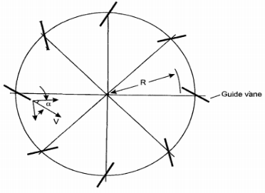
Fig. (a) Plan view of guide vanes
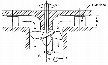
Fig. (b) Axial-flow propeller-type turbine, guide vanes, and runner
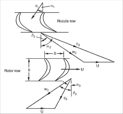
Velocity Diagram
The runner blades are long and there is a large difference in radii between the hub and tip of the blades. Therefore velocity diagrams are drawn at the mean radius of the blade. The axial flow velocity is constant as inlet and exit and hence
VIf= V2f = Vf
The inlet velocity diagram is constructed by subtracting blade velocity vector u from absolute velocity vector V1 which makes an angle αl to u to obtain relative velocity Vrl as shown in Fig. 6-14.
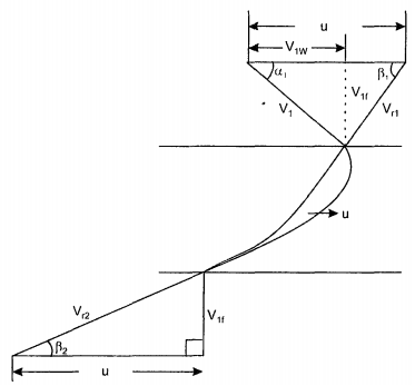
Fig. Inlet and exit velocity diagrams
For shock-free entry, the relative velocity Vrl must be tangent to the inlet tip of the blade. The velocity Vrl makes an angle βI with horizontal. The exit velocity diagram is constructed by drawing relative velocity at exit Vr2 tangential to exit tip of the blade, superimposing peripheral velocity u, we obtain absolute velocity V2 which is axial. The velocity diagrams are shown in Fig. 6-15.
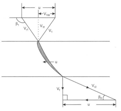
Fig. Inlet and exit velocity diagram.
For maximum efficiency, the whirl component V2w at exit must be zero because velocity V2 is axial and also V2 = V2f
Writing Euler's equation as
E =  as V2w = 0 (6.15)
E =  (6.16)
From the inlet diagram, we have
V1w = u-Vf cot (180-β1)=u+Vf cot β1
Substituting this value of V Iw in eq. 6.16
E = 
E =  (6.17)
If E is constant along the blade radius, Vf is constant over the cross-sectional area, then u increases from hub to tip, u cot β1 must decrease to keep E constant that means β1 must increase from hub to tip and the blade must therefore be 'Twisted'. The profile of the twisted blade changes along the length of the blades. It is difficult to manufacture twisted blades than constant profile (cylindrical) blades. The long blades are cast as an integral part of the tile runner or welded to the hub. In practice, the runner blade is divided into several regions of flow around the blades. The velocity diagrams are drawn for such domain and the power developed computed.
Flow rate is given by the equation
Q = area x Velocity of flow
 (6.18)
Where
D1 = diameter at the tip
Dh = diameter at the hub
Vf = flow velocity
Hydraulic efficiency is runner power by hydraulic power
ηh =  (6.19)
Mechanical efficiency ηm = 
ηm =  (6.20)
Overall efficiency = 
ηo =  (6.21)
We get,
ηo = ηm × ηh (6.22)
H is effective head H = H1+ H2 as shown in Fig. Of Kaplan turbine installation. Fig. Shows overall efficiency against the percentage of design power for various turbines.
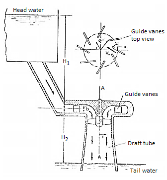
Fig. Axial flow turbine
The characteristic curve for the axial flow Kaplan turbine is similar to the radial flow Francis turbine. The Pelton efficiency curve is flatter but maximum efficiency is lower than Francis turbine. Kaplan has better characteristics than propeller type. The two methods of determining the specific speed of propeller/Kaplan turbine is
Given below:
ωT = 
And
NT = 
Key Takeaways:
- The Kaplan type consists of an axial flow runner with 4 to 6 blades of an aerofoil shape. The spiral casing and guide vanes are similar to the Francis turbine. The runner blades are long to accommodate a large flow rate and therefore pitch/chord ratio of runner blades is 1 to 1.5 and hence the number of blades is small.
- The flow rate is given by
Q = π/4 ( D21 – D2h) Vf
3. Specific speed is given by
NS = 
References:
1. Introduction to Fluid Mechanics, James E.A., John and Haberm W.A., Prentice Hall of India
2. Fluid Mechanics, Jain A.K., Khanna Publication
3. Engineering Fluid Mechanics, Garde R.J. And MirajGoankar, Nemchand &Bros, Roorkee, SCITECH, Publication (India) Pvt. Ltd.
4. Fluid Mechanics and Fluid Power Engineering, Dr. D.S. Kumar, S.K. Kataria& sons
5. Fluid Mechanics, Frank M. White, McGraw Hill Publication