Unit – 1
Control System controls
Hydraulic
The Hydraulic system of interest to control engineers may be classified into,
1.Liquid Level system
2.Hydraulic devices
The liquid level system consists of storage tanks and connecting pipes. The variables to be controlled are liquid height in tanks and flow rate in pipes. The driving force is the relative difference of the liquid heights in the tanks. The Hydraulic devices are devices using incompressible oil as their working medium. In this we will be learning transfer function of hydraulic system.
These devices are used for controlling the forces and motions. The driving force is the high-pressure oil supplied by the Hydraulic pumps. Liquids are slightly compressible at high pressures.
In hydraulic system, the compressibility effects may be neglected and conservation of volume is used as the basic physical law. The variables of hydraulic system are volumetric flow rate, q and pressure, R The volumetric flow rate, q is through variable and it is analogous to current. The pressure, P is across variable and it is analogous to voltage.
Three basic elements of hydraulic systems are the Resistance, Capacitance and inertance. The liquid flowing out of a tank can meet the resistance in several ways. Liquid while flowing through a pipe meet with resistance due to the friction between pipe walls and liquid. Presence of valves, bends, coupling of pipes of different diameter also offer resistance to liquid flow.
The capacitance is an energy storage element and it represents storage in gravity field. The inertance represents fluid inertia and is derived from the inertia forces required to accelerate the fluid in a pipe. It is also an energy storage element. But the energy storage due to inertance element is negligible compared to that of capacitance element.
Servomotors: These motors are used in feedback control system. These are also known as control motors. These motors should have low rotor inertia and high speed of response. The servomotors used in the feedback control systems should have linear control signal and rotor speed.
Types of Servomotors:
(a). A.C. Servomotors
(b). D.C. Servomotors
(a). A.C. Servomotors:
A.C servomotor is a two-phase ac induction motor. There are two windings in this motor, one is fixed or reference winding is supplied with a fixed voltage and frequency from a constant voltage source. Second winding is control winding with variable supply voltage of same frequency as reference winding but having a phase displacement of 900 electrical. A flux is induced due to the phase change which cuts the conducting bars of rotor and causes a time varying current, this current produces a time varying flux and reacts with the stator flux causing the rotor to rotate.

Fig 1. AC Servomotor
The rotor of A.C. Servo motors are of two types,
(a). Squirrel Cage Rotor
(b). Drag cup type rotor
(a). Squirrel cage rotor: They have high resistance as the rotor is having large length and small diameter. The air gap here is kept small.

Fig 2. Squirrel cage rotor
(b). Drag cup type motor: For the drag cup rotor there are two air gaps. For the rotor a cup of non-magnetic conducting material is used. A stationary iron core is placed between the conducting cup to complete the magnetic circuit. The resistance of drag cup type is high and therefore, has high starting torque. Generally aluminium is used for cup.
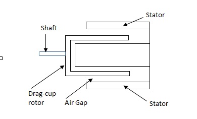
Fig 3. Drag Cup type rotor
Torque-speed characteristic:
The torque speed characteristics of the two phase servomotor depends on ratio of reactance to resistance(X/R).
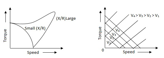
Fig 4. The torque speed characteristics of the two phase servomotor
(i). For high ‘R’ and low X, the characteristic is linear and
(ii). For high X and low R, it becomes non-linear.
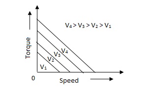
Fig 5. Torque-speed characteristic for various voltage
The torque-speed characteristic for various voltage is almost linear.
(b). D.C. Servomotor:
D.C. Servomotor are separately excited or permanent magnet dc servomotors. The armature of D.C. Servomotors is having large resistance and hence torque-speed characteristic is linear.
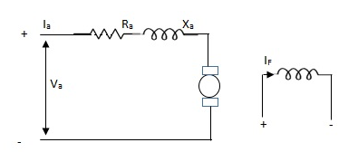
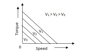
Fig 6. (a) DC Servomotor (b) Torque-speed characteristics
The above graph fig (b), clearly shows that the torque-speed characteristics is a function of control winding voltage as shown below.
T = mw + KVc -- (1)
Where T = Torque developed by motor
w = angular velocity
Vc = control winding voltage
Taking laplace of above equation (1),
T(S) = mS Q(S) + KVc - - (2)
T(S) = JS2Q(S) + FSQ(S) - - (3)
Above equation(3) is the dynamic equation with,
J – moment of inertia
F – coefficient of friction of motor
From equation (2) and (3) the block diagram will be,

Fig 7. Block Diagram of DC Servomotor
Q(S)/Vc = K/Js + F + m - - (4)
Key takeaway
Comparison between A.C. Servomotor & D.C. Servomotor
| A.C. Servomotor | D.C. Servomotor |
|
|
|
1. | They are less efficient | They are more efficient |
2. | They have low power output | They have high power output |
3. | No noise so has smooth operation | These motors have noisy operation |
4. | They do not have any radio frequency noise | These motors have brushes so produce radio frequency noise |
5. | They are maintenance free because of no brushes and slip rings | For these motors, maintenance is required. |
Consider the flow through a short pipe connecting two tanks. The Resistance, R for liquid flow in such a pipe or restriction, is defined as the change in the level difference, necessary to cause a unit change in the flow rate.
R = Change in level difference/Change in flow rate
The Capacitance, C of a tank is defined to the change in quantity of stored liquid necessary to cause in the potential (head).
C = Change in liquid stored/Change in head
A simple liquid level system is shown in the below figure with steady flow rate, Q and steady state head, H.
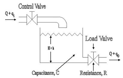
Fig 8. Liquid Level System
Let Q = Steady state flow rate(before any change has occured)
Qi = Small deviation of inflow rate from its steady-state value
Qo = Small deviation of outflow rate from its steady-state value
H = Steady state head (before any change has occurred)
h = Small deviation of head from its steady state value
Let the system be considered linear. The differential equation governing the system is obtained by equating the change in flow rate to the amount stored in the tank. In a small time interval dt, let the change in flow rate be (qi - qo) and the change in height be dh.
Now, Change In storage = Change in flow rate
C dh = (qi - qo) dh

Qo = h/R
On substituting for qo, we get,
 RC dh/dt + h = qi R
The above equation is the differential equation governing the system. The term RC is the time constant of the system .On the Laplace's transform of above equation we get,


The above equation is the required transfer function of the Hydraulic system.
- Collection of components which allows to follow the desired course.
- In a car: ensure that wheels are pointing in the desired direction of motion.
- Convert rotary motion of the steering to the angular turn of the wheel.
- Mechanical advantage is used in this case.
- The joints and the links should be adjusted with precision.
- Smallest error can be dangerous
- Mechanism should not transfer the shocks in the road to the driver's hands.
- It should minimize the wear on the tyres.
RACK AND PINION STEERING SYSTEM
- The pinion moves the rack converting circular motion into linear motion along a different axis
- Rack and pinion give good feedback there by imparts a feel to the driving
- Most commonly used system in automobiles now.
- Disadvantage of developing wear and there by backlash.
RECIRCULATING BALL
- Used in Older automobiles
- The steering wheel rotates the shaft which turns the worm gear.
- Worm gear is fixed to the block and this moves the wheels.
- More mechanical advantage.
- More strength and durable
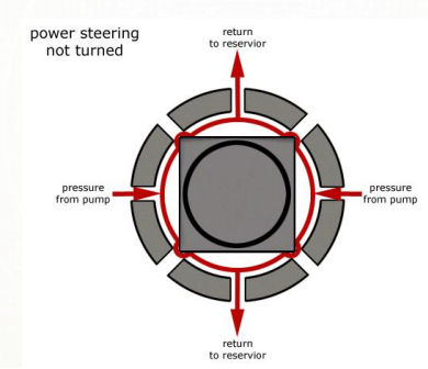
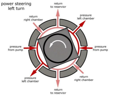
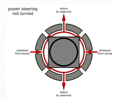
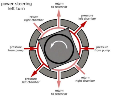
POWER STEERING
- Too much physical exertion was needed for vehicles
- External power is only used to assist the steering effort.
- Power steering gives feedback of forces acting on the front wheel to give a sense of how wheels are interacting with the road.
- Hydraulic and electric systems were developed.
- Also, hybrid hydraulic-electric systems were developed.
- Even if the power fails, driver can steer only it becomes heavier.
ELECTRIC POWER STEERING
- Uses an electric motor to assist the driving
- Sensors detect the position of the steering column.
- An electronic module controls the effort to be applied depending on the conditions.
- The module can be customised to apply varying amounts of assistance depending on driving conditions.
- The assistance can also be tuned depending on vehicle type, driver preferences
Generally, there are three types of EPS systems: column-type, rack-type and pinion type. The selection of different configurations depends on the package and in-vehicle environment.
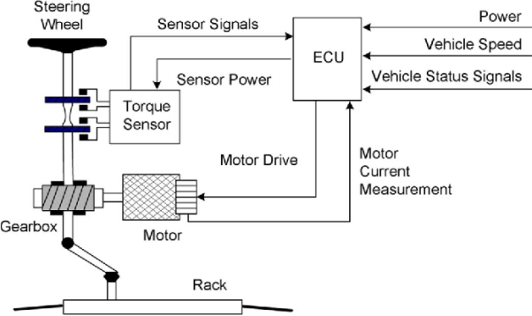
The schematic arrangement of a column-type EPS system is shown in figure
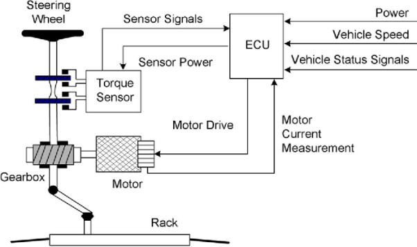
The EPS consists o f a torque sensor, which senses the driver’s movements of the steering wheel as well as the movements of the vehicle; an ECU, which performs calculations on assisting force based on signals from the torque sensor; a motor, which produces turning force according to the output from ECU; and a reduction gear, which increases the turning force from the motor and transfers it to the steering mechanism. The rest of the steering system: Steering Wheel (or hand wheel, HW), Intermediate Shaft (IShaft), and Rack & Pinion are also shown. Basically, the control procedure can be summarized as follows:
1) The torque sensor estimates the torque, which is the command from the human to steer the car, by the torsion bar mechanism inside.
2) ECU calculates the assistant torque based on the command torque (from torque sensor), the vehicle speed (from speed sensor or in-vehicle network) and the status of the electric motor, and then sends the command to the electric motor.
3) The electric motor generates the assistant torque according to the command from the ECU and transfers it to the column through a worm gear mechanism.
4) With the power assistance from the electric motor, the pinion and rack turns the wheels.
STEERING WHEEL DYNAMIC MODEL
The upper part of the system model is the dynamic model o f the human wheel. The MatLab model is as follows:

The differential equation of the steering wheel is:
Th – Ts = Jhw  + Bhw
+ Bhw  + Bhw
+ Bhw  + Khw θhw
Where 7/, and Ts are the torque from driver and torque sensor, respectively. 8hw denotes the angle o f rotation of the steering wheel. Jhw, Bhw and Khw are moment of inertia, damping coefficient and stiffness coefficient. To simplify the model, the stiffness coefficient can be neglected. That is to say, the steering wheel is rigid connection. The dynamic model can be simplified as follows:


THE DYNAMIC MODEL OF PINION AND RACK ASSEMBLY
The pinion and rack are modeled as a mechanic system consists of a mass and a spring. The differential equation of the steering wheel is:
Tr + Tf = Jr  + Br
+ Br  + Kr θ
Where Jr, Br and Kr are the moment of inertia, damping coefficient and stiffness coefficient, respectively. Tr and Tf denote torque from road wheels and steering torque, respectively. 6 represents the road wheel position. The model of the pinion and the rack is as follows
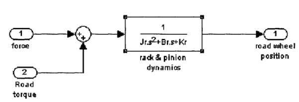
Both of the force torque and the road torque have the same positive direction. Also, to simplify the system, the stiffness coefficient is assumed to be zero. As a result, the model can be simplified as follows

A manipulator is a mechanical system formed by the connection of a set of rigid bodies, links, through joints. Joints provide each pair of connected links with some freedom of relative motion. The description of the spatial location of a rigid body is therefore the basis for the spatial description of a manipulator. The configuration of a rigid body is a description of its position and orientation. The position of a rigid body is determined by a description of the position of an arbitrary point attached to the rigid body. The orientation of a rigid body is determined by the description of its rotations about this point.
Position of a Point
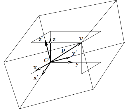
Let us consider a point P of an Euclidean affine space E, where an arbitrary point O has been selected as the origin. The position of P is given by the vector p =  P. With respect to O, the positions of points: P1, P2,..., Pn are described by the vectors: p1 =
  P1, p2 =
  P2,..., pn =
  Pn.
Pn.
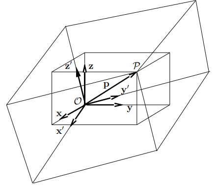
For points of the 3-dimensional space, positions are described by vectors p ∈ R3. Let {x, y, z} be an orthonormal basis of R3. The components of a vector p with respect to this basis are identical to the coordinates of P given with respect to the coordinate frame R (O, x, y, z).
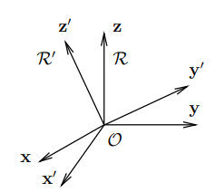
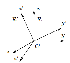
Taking the components of the vector p with respect to another orthonormal basis {x’, y’, z’} correspond to a representation of P in a coordinate frame having the same origin, O, and using the unit vectors x’, y’, z’, i.e. R’ (O, x’, y’, z’), as shown in Figure. The relationship between these two representations is given by the base transformation or the coordinate transformation between the two frames of same origin.
Rotation Transformation
Rotation transformations are transformations that operate on the unit vectors of coordinate frames, while conserving the frame origins. These transformations are equivalent to transformations between orthonormal bases. A rotation transformation is defined by the relationships between the unit vectors of two coordinate frames. The rotation transformation between R (O, x, y, z) and R’ (O, x’, y’, z’), of identical origin O, is described by a 3 × 3 orthonormal rotation matrix S. The columns of S are the components of the three-unit vectors x’, y’, and z’ expressed in the coordinate frame R.
S = (x’(R) y’(R) z’(R))
S-1 = ST
The rows of S define, therefore, the components of the three unit vectors x, y, and z expressed with respect to the coordinate frame R’.
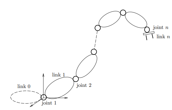
A manipulator is treated as a holonomic system with a structure of an open kinematic chain of n+1 rigid bodies, i.e., links, articulated through n revolute and/or prismatic joints having one degree of freedom.
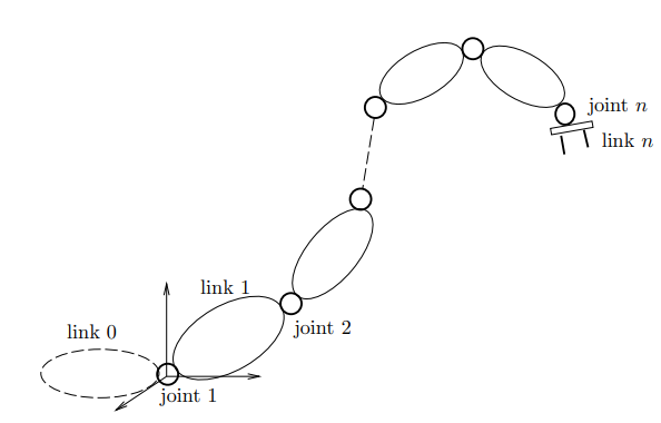
The kinematic relationship between a pair of adjacent links in the chain is described by the coordinate transformation between two coordinate frames attached to the two links. Links are numbered from 0, the base, to n, the end-effector, while joints are numbered from 1 to n
A coordinate frame Ri (Oi, xi, yi, zi) is attached to link i. The position and orientation of the link i with respect to link i−1 is described by the transformation between a coordinate frame Ri−1(Oi−1, xi−1, yi−1, zi−1) attached to the link i − 1 and Ri
Parameters of Denavit-Hartenberg
The kinematic relationship between a pair of adjacent links i − 1 and i connected through a one-degree-of-freedom joint i can be completely determined by a set of four parameters (αi, ai, θi, ρi), called parameters of Denavit-Hartenberg. These parameters define the homogeneous transformation between the two coordinate frames attached to the two links. With the convention shown in Figure, the Denavit-Hartenberg parameters are defined as
αi: the angle between the z-axes of Ri and Ri+1, measured1 about xi;
ai: the length of the common normal to the z−axes of Ri and Ri+1, measured along xi;
θi: the angle between the x-axes of Ri−1 and Ri measured about zi.
ρi: the distance between the x-axes of Ri−1 and Ri measured along zi.

Measuring instruments are used to measure a quantity. When choosing an instrument, the static calibration and static performance of an instrument must be considered
The characteristics of measuring instruments can be classified into the following categories:
1)Static performance characteristics
2)Dynamic performance characteristics
Static calibration refers to the procedure where an input is constant or a variable is applied to an instrument. Instruments are manufactured based on the property of irreversibility or directionality. This implies that change in an input quantity will cause a corresponding change in the output. A calibration standard must be at least ten times more accurate than the instrument to be calibrated.
Static performance characteristics include the linearity performance of the instrument, static sensitivity of the instrument, repeatability of the same results, hysteresis resolution, and the readability of the results.
Static performance characteristics influence data acquisition if the instruments are not properly calibrated prior to the measurement. Understanding quality control and quality assurance procedures for handling equipment is essential for the PE exam.
Linearity
If the relationship between the output and input can be expressed by the equation Q0= P + RQ1, where P and R are constants, then the instrument is considered linear. Linearity is never fully achieved in real-world situations, and the deviations from the ideal are referred to as linearity tolerances. For example, 3% independent linearity means that the output will remain within the values set by two parallel lines spaced ± 3% of the full-scale output from the idealized line. If the input-output relationship is not linear for an instrument, it may still be approximated to a linear form when it is used over a very restrictive range.
Static Sensitivity
Static sensitivity can be defined as the slope of a calibration curve.
Sensitivity = Q0/Q1
Sensitivity influences the input parameters of an instrument. The sensitivity factor can also be referred to as sensitivity drift or scale factor drift.
Repeatability Error
When an instrument is used to measure the same or an identical input many times and at different time intervals, the output is never the same; it deviates from the recorded values. This deviation from the ideal value is referred to as repeatability error.
Hysteresis-Threshold Resolution
When testing an instrument for repeatability, it is often noted that the input-out value does not coincide with the inputs, which are continuously ascending and descending values. This occurs because of hysteresis, which is caused by internal friction, sliding, external friction, and free play mechanisms. Hysteresis can be eliminated by taking readings corresponding to the ascending and descending values of the input and calculating their arithmetic mean.
Professional engineers who work with measurements and instrumentation should understand calibration procedures of various instruments for proper data acquisition.
Machine Tools
Computer Integrated Manufacturing (CIM) encompasses the entire range of product development and manufacturing activities with all the functions being carried out with the help of dedicated software packages. The data required for various functions are passed from one application software to another in a seamless manner.
For example, the product data is created during design. This data has to be transferred from the modeling software to manufacturing software without any loss of data. CIM uses a common database wherever feasible and communication technologies to integrate design, manufacturing and associated business functions that combine the automated segments of a factory or a manufacturing facility. CIM reduces the human component of manufacturing and thereby relieves the process of its slow, expensive and error-prone component.
CIM stands for a holistic and methodological approach to the activities of the manufacturing enterprise in order to achieve vast improvement in its performance. This methodological approach is applied to all activities from the design of the product to customer support in an integrated way, using various methods, means and techniques in order to achieve production improvement, cost reduction, fulfilment of scheduled delivery dates, quality improvement and total flexibility in the manufacturing system.
CIM requires all those associated with a company to involve totally in the process of product development and manufacture. In such a holistic approach, economic, social and human aspects have the same importance as technical aspects. Manufacturing industries strive to reduce the cost of the product continuously to remain competitive in the face of global competition.
In addition, there is the need to improve the quality and performance levels on a continuing basis. Another important requirement ison time delivery. In the context of global outsourcing and long supply chains cutting across several international borders, the task of continuously reducing delivery times is really anarduous task. CIM has several software tools to address the above needs. Manufacturing engineers are required to achieve the following objectives to be competitive in a global context.
• Reduction in inventory
• Lower the cost of the product
• Reduce waste
• Improve quality
• Increase flexibility in manufacturing to achieve immediate and rapid response to:
• Product changes
• Production changes
• Process change
• Equipment changes
• Change of personnel
Basic components of NC system
1.Input medium
2.MCU
3.Machine Tool
Basic Components of an NC System and NC system consists of three basic components:
Program of instructions: The detailed step-by-step commands that direct the actions of the processing equipment. In machine tool applications, the program of instructions is called a part program, and the person who prepares the program is called a part programmer. In these applications, the individual commands refer to positions of a cutting tool relative to the worktable on which the workpart is fixtured. Additional instructions are usually included, such as spindle speed, feed rate, cutting tool selection, and other functions. The program is coded on a suitable medium for submission to the machine control unit. (2) Machine control unit MCU: Consists of a microcomputer and related control hardware that stores the program of instructions and executes it by converting each command into mechanical actions of the processing equipment, one command at a time. The related hardware of the MCU includes components to interface with processing equipment and feedback control elements. The MCU also includes one or more reading devices for entering part programs into memory. The MCU also includes control system software, calculation algorithms, and translation software to convert the NC part program into a usable format for the MCU. Submission to the machine control unit.
(2) Machine control unit MCU: Consists of a microcomputer and related control hardware that stores the program of instructions and executes it by converting each command into mechanical actions of the processing equipment, one command at a time. The related hardware of the MCU includes components to interface with processing equipment and feedback control elements. The MCU also includes one or more reading devices for entering part programs into memory. The MCU also includes control system software, calculation algorithms, and translation software to convert the NC part program into a usable format for the MCU.
Prime movers
The actual meaning of prime mover is a primary source of power. It means all the machinery that provide power for performing different mechanical work. Technically, it is a group of machines that transform energy from thermal, electrical or pressure into mechanical form for use in different sources for some mechanical work. Engines and turbines are examples.
The prime movers are listed based on the sources of energy utilized by them.
A. Thermal prime movers These are the prime movers which use the thermal energy of source to produce power. Different thermal prime movers are given below: -
Fuels (Heat engines): - These prime movers use several fuels like petrol, diesel, oil, gas to produce mechanical power. Heat engines are two types: -
1. External combustion engines: -Reciprocating steam engines Steam turbine Closed cycle gas turbine
2. Internal combustion engines: -Reciprocating I.C. Engines Open cycle gas turbine
- Nuclear (Nuclear power plant): - This prime mover utilises the heat energy of atoms by fission or fusion method to develop the mechanical power. It is chiefly used in nuclear power plants. Different radioactive components like uranium, thorium is used for these fission or fusion process in a nuclear reactor.
- Geothermal: - In this kind of prime mover the heat energy is recovered from a certain depth or the hot part of the earth beneath earth surface then it is transformed into mechanical by the proper engine.
- Biogas: - Biogas is principally produced from garbage or any other waste which is used to generate power by the prime mover in a biogas plant.
- Solar energy: - The solar energy spread to the earth in the form of radiation or electromagnetic waves. This energy trapped in with the help of solar panel made up of semiconductor element. This heat energy is then turned into power.
B. Non-thermal prime movers: - These kinds of prime movers do not use the heat energy to transform it into mechanical power. The following are the non-thermal prime movers:
- Hydraulic turbines: - This kind of prime mover uses the stored potential energy of water to generate power.
- Wind power: - With the help of the wind turbine, wind energy is transformed into power.
- Tidal power: - The energy of tides from the ocean is transformed into power by the use of the turbine which is known as tidal power.
System generators
System Generator is a powerful tool that integrates Xilinx FPGA design process with MATLAB’s Simulink which uses a high-level description to easily realize a complex system. We first design the system and verify its functionality in the Simulink environment. The graphical high-level description of Simulink significantly facilitates modeling, simulating, and analysing the design.
A control system is a set of mechanical or electronic devices which control the other devices. In control system behaviours of the system is desired by differential equations.
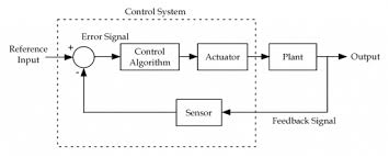
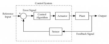
The above figure shows a feedback system with a control system. The components of control system are:
i) The actuator takes the signal transforms it accordingly and causes some action.
Ii) Sensors are used to measure continuous and discrete process variables.
Iii) Controllers are those elements which adjust the actuators in response to the measurement.
Open loop systems:
This is the loop of control system without any feedback. In this the control action is not dependent on the desired output.

Fig. 9 open loop control system
Example of open Loop systems are the traffic signals, Automatic washing machine and in fields control d.c. Motor.
G(s) = c(s)/R(s) -------(1)
Closed loop systems:
This is a type of control system with feedback. In this type of system. The control action is dependent on the desired output.

Fig 10. Closed Loop control system
The error signal is again fed to controller to the error and get desired output.
G(s) – forward amplification
H(s) _ Reverse amplification
Above system is with negative feedback.
Positive feedback is used only in oscillators and other use is not known as discussing only negative feedback.
[ R(s) – c(s) H (S) ] G(s) = c(s)
R (s) G(s) = [1+G(s) H(s)] c(s)
C(s)/R(S) = G(S)/1+G(s) H(s)
So, the transfer function of closed Loop system is
C(s)/ R(S) = G(s)/ 1+G(S) H(S) --------(2)
If numerator of above equation (2) is equalized to zero we get zeros of closed Loop Transfer function [G(S) = 0]
If dominator of equation (2) is equaled to zero we get polls of the closed loop transfer function [ 1+G(s) H(S) = 0]
1+ G(S) H(s) = 0 [ characteristic Equation]
Stability of the system is determined by the location of its poles.
Comparisons between open Loop and Closed Loop system
Open Loop System | Closed Loop system |
1.It does Not have any feedback. | 1. This system comprise of feedback |
2.As no feedback so easier to build. | 2.As it has feedback so difficult to build |
3.Theaccuracy of this system depends on the calibration of input. | 3.They are accuracy because of the feedback. |
4.Open Loop system are more stable. | 4.In closed Loop system stability depends on system components. |
5.optimization is not possible | 5. Optimization is possible |
6.These systems are not reliable. | They are more reliable |
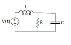
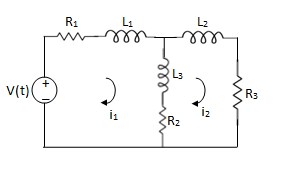
Example 1. For the circuits given below write the voltage equations:
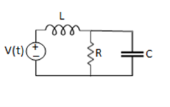
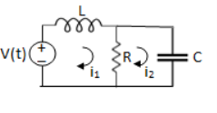
Solution: Let current i1be in loop 1 current and i2 for loop 2
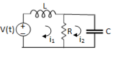


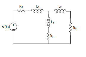
Que. Write the loop equations for the given circuit below?
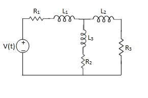
Solution:
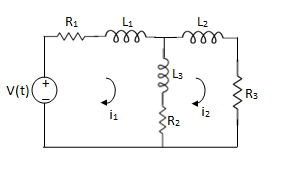
For loop 1

For loop 2

Q) Write the integro-differential equation for the loop currents shown below.
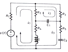
Sol: Equation for loop 1 with current i1
v(t)=(R1+R2+R4)i1 +L -R2 i2+ R5i3
Equation for loop 2 with current i2
-R2i1+(R2+R3) i2 + +R3i3 = 0
Equation for loop 3 with current i3
V(t) = R1i3+R3i3+(R1+R3+R5) i3+
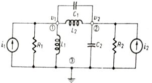
Q) For the given network write the integro differential equation?
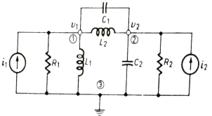
Sol: Let V1 and V2 be the node voltages.
Equation for node v1 will be
 +
+ +
+ +C1
+C1 = i1
= i1
 + C2
+ C2 + C1
+ C1 +
+ = i2
= i2
It is a technique for solving differential equations. The time domain differential equations are transformed into algebraic equation of frequency domain. After solving the algebraic equation in frequency domain, the result then is finally transformed to time domain form to achieve the ultimate solution of the differential equation.
The Laplace Transform is given as
F(s)= dt
dt
The advantages of Laplace Transform are:
1) It is systematic.
2) It gives total solution (transient and sustained solution) in one operation.
3) The initial conditions are automatically specified in the transformed equations.
There are many functions which do not have Laplace Transforms. These functions are not generally used in analysis of linear systems. But some conditions can be defined to get Laplace transformation of such functions. The Dirichlet condition defines the necessary condition for transformation of some functions such as:
a) The function should be continuous. The function should be single-valued.
b) The function must be of exponential order.
Properties of Laplace Transform:
1) Linearity Property:
If f1(t) and f2(t) are two functions of time. Then, in domain of convergence
L[a f1(t)+b f2(t)]=a + b
+ b
=aF1(s)+bF2(s)
2) Differentiation Property:
If x(t) is function of time then Laplace transform of nth derivative is given as


3) Integration Property:
The Laplace of nth order integral is given as
L[ ]=
]= +
+
L[f-n(t)]= +
+ +
+ +……….
+……….
As  ……..=0. Hence
L[f-n(t)]=
Laplace Transform of Basic R, L and C components
LAPALACE TRANSFORM:
If LT[f(t)]= F(s)
Where F(s)= dt
dt
f(t) F(s)
F(s)
 sF(s)-f(0-)
 f(t)
f(t) S2F(s)-sf(0-)-f’(0-)
Now, we find Laplace for 
 =
= +
+
Now if f(t)=ic(t) [current through capacitor]
 =
= +
+
 =
= +
+
=[q(0)-q( )]+
)]+
=[q(0)-0]+
Multiplying both sides by 1/C
 =
= +
+
Vc(t)= +
+
Vc(t)=Vc(0)+
By Laplace Transform
Vc(s)= +
+
Vc(s)= +
+

Fig 11. Laplace transformed circuit for C
Now by source conversion

Fig 12 .Source transformed circuit for C
 =
= +
+
Now if f(t)=VL(t) [voltage across inductor]
 =
= +
+
 =
= +
+
= -
- ]+
]+
= -0]+
-0]+
Multiplying both sides by 1/L
 =
= +
+
iL(t)=iL(0)+
By Laplace Transform
IL(s)= +
+
IL(s)= +
+
NOTE: Voltage------->Series circuit
Current------->Parallel circuit
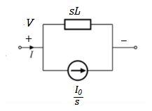
Fig 13. Laplace transformed circuit for L
By source transformation

Fig 14. Source transformed circuit for L
Current through capacitor
iC(t)=
IC(s)=C[sVc(s)-Vc(0)]
Vc(s)= +
+
Voltage about inductor,
VL(t)=
VL(s)=L[sIL(s)-iL(0)]
IL(s)= +
+
It is the ratio of Laplace transform of the output to Laplace transform of input with all initial conditions zero.

Fig 15. System with Transfer Function G(s)
Poles and zero of a Transfer Function:
The transfer function can be represented by the ratio of two polynomials
G (S) = a0sn+a1 sn-1-------+an/b0sm+b1sm-1+-----+bn
a0—an ---- constants
G(S) = K(s+z1) (s+z2) (as2+bs+c)/(S+A) (s+p2) (As2+Bs +c)
K= a0/b0 ( Gain of system)
For poles –They are the values of s for which
G(S)
(S+p1)(S+p2)(AS2 + BS + C) = 0
S= p1, -p2 , -B±B2-4Ac/2A
For ZEROS – They are the values of s for which
G(S)0
S=-z1, -z2 , -b±b2-4ac/2a
- Location of poles and zeros in s place determines the reliability of the system
- There can be multiple poles and zeros
- The numerator of transfer function when equalized to zero gives zero of system
- The denominator of transfer function which equalized to zero gives poles of system.
Key takeaways
- The numerator of transfer function when equalized to zero gives zero of system.
- The denominator of transfer function which equalized to zero gives poles of system.
Mechanical System
(a) Translational system
(b) Rotational system
(a) Translational system
The motion that takes place along a straight line is called translational motion. The forces that resist motion are -
Inertia: A body with mass ‘N’ acceleration ‘a’ will produce inertia fm(t)= malt N’ acceleration ‘a’ will produce inertia
fm(t)= M a(t)
In terms of velocity
Fm(t) = M dv(t)/dt
In terms of displacement
Fm(t)= Md2/dt2µt
Damping force: The damping force is proportional to velocity for vis case function
F0(t) = B(t) = B dx(t) /dt
B Damping coefficient N/M sec
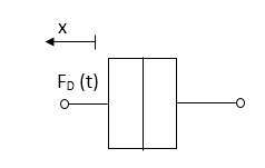
Fig 16. Damping force
Spring force: A spring stores potential energy. The releasing force of a string is proportional to the displacement.
Fk(t)  x(t)
x(t)
Fk(t) = k x (t)
Fk(t) = k 
K = string constant N/m.

Fig 17. Spring force
Fk(t) = k 
K = string constant N/m.
(b) Rotational system:
The motion of a body about a fixed axis is called as Rotational motion. The types of torques which can resist the motion are
Inertial Torque: The inertial torque is the product of moment of inertia I and angular acceleration.
TI(t) = J (t)
(t)
TI(t) = Jd/dt w(t)
TI(t) = Jd2ø(t)/dt2(N-m)
W (t) – Angular velocity
Ø(t) = Angular displacement
Damping Torque: It is product of damping efficient B and angular velocity w
T0 (t) = B w(t)
T0(t) = B d/dt ø(t)
Spring Torque: It is the product of torsional stiffness and angular displacement
Tø(t) = k ø(t)
K = N.m/rad
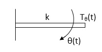
Fig 18. Spring Torque
D’Alembert’s Principle
For anybody, the algebraic sum of externally applied forces and the forces resisting motion in any given direction is zero.
Ex.
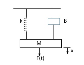
In above figure applying D’Alemberts principle to write the equation of motion
As force f(t) acts downwards all other forces (of k,B,x) acts Opposite to it to considering f(t) as the and all other forces negative.
F(t)+fm (t) + fD(t) +fx(t) =0
f(t)- M d2x(t)/dt2+B dx(t)/dt +x(t)
Example
Q.1 Draw the free body diagram and write the differential equation for system below.
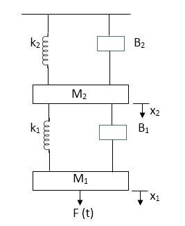
Fig 19. Mechanical system
Sol: The free body diagram for M1 will be
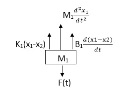
Fig 20. FBD
F(t) = M1 d2/dt2x1+ B1 d/dt (x1-x2)+ k1(x1-x2)
Similarly for M2we have
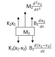
Fig 21. FBD
K1(x1-x2) + B1d/dt(x1-x2) = k2x2+M2d2/dt2+B2dx2/dt
Electrical System
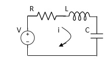
Fig 22. RLC Circuit
Example-1 For circuit shown above find value of current I?
Applying Kirchoff’s voltage Law
V= Ri +Ldi/dt +1/c
V= Rdq/dt + L d2q/dt2+q/c
Now By kirchoff’s current low
I= V/R+ 1/L  + cdv/dt
But V= dø/dt
I= 1/R dø/dt + 1/L ø+cd2ø/dt2
But v= dø/dt
I= 1/R dø/dt+ 1/L. ø+c d2ø/dt2
Example-2 For the given mechanical system below draw the analogus system (force. Voltage )& find V0(s)/V1(s)
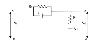
Soln.
Let Z1 = R2 11 1/c2
=R2*1/c2s/R2+1/c2s
Z1= R2/1+R2c2s
Let Z2 = R1+1/c1s
Z2= 1+R1c1s/c1s
V0(s)/vi(s) = z2/z1+z2
=1+R1c1s/c1s/R2/1+R2c2s+1+R1c1s/c1s
V0(s)/v0(s) =(c1+R1c1s) (1+R2c2s)/R2c1s+1+sR1c1s2R1R2c1c2
Electronic system and Electro-mechanical system.
Stepper Motors
It is a device whose output is completely controlled by the input pulses. There are two types of stepper motors:
a) Variable Reluctance
b) Permanent Magnet
A variable reluctance stepper motor consists of stator having a common frame and rotate n a common shaft. Rotor and stator have toothed structure and teeth are of same size so that it can be aligned on same axis. The stator re pulse excited while the rotor is unexcited. When stator is excited stator and rotor teeth are aligned to minimum reluctance position. The stator torque of the rotor depends on the displacement  .
.
There are two positions of zero torque:
i) For  =0 when rotor and stator are aligned is called stable position because slight disturbance from this position in either direction brings the rotor back to its original position.
Ii) For  = 180/T when tooth and stator are aligned is called unstable position. This is because of slight disturbance from this position in either direction makes the rotor move away from it.
For multiple stack stepper motor, Step angle  = 360/nxT
n: number of stacks
T: number of rotor teeth
These motors are used in computer peripherals.
Tacho Generators
These are electromechanical devices which convert mechanical input at their shaft to corresponding electrical output. It is basically used to measure speed of motor. It has negative feedback. These devices are most commonly used to find speed of any rotating machine.
| D.C. Tachometer | A.C. Tachometer |
1. | They convert rotational speed into a proportional dc voltage. | They convert the rotational speed into a proportional ac voltage. |
2. | It uses a permanent magnet for producing magnetic field. It contains iron core rotor. | It works on principle of induction generator. |
3. | The permanent magnet controls the magnetic field therefore the induce voltage at terminal of armature is proportional to shaft speed. | The reference winding is supplied by reference voltage and the output voltage is induced across the output winding. |
4. | The polarity depends on direction of rotation. | The amplitude and phase depends on the direction of rotation. |
Synchros
Its construction is similar to a three-phase alternator. The stator is made of laminated silicon steel and rotor is dumbbell shaped magnet with a single winding.
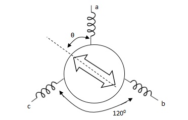
Let the applied a.c. Voltage to the rotor is,
er = ErSinwot
Let the rotor be at angle of ϴ, then voltage in each stator coil with respect to neutral,
Ean = KErSinwot cos(ϴ)
Ebn = KErSinwotcos(ϴ + 1200)
Ecn = KErSinwotcos(ϴ + 2400)
Magnitude of stator terminal voltage,
Ecb = Ecn – Ebn
= KErSinwot[cos(ϴ + 2400) – cos(ϴ + 1200)]
= KErSinwot(√3 Sinϴ)
Ecb = √3KErSinwot Sinϴ
Similarly,
Eac = √3KErSinwot Sin(ϴ + 1200)
Eba = √3KErSinwot Sin(ϴ + 2400)
When ϴ = 0, Ecb, Ean = 0
Hence, input to the synchro transmitter is the angular position of motor shaft and output are three phase voltage which are function of shaft position.
Synchro Transformer
Its basic working principle is similar to the synchro transformer. Here the rotor is cylindrical type. It is an electromechanical device. The combination of synchro transmitter and synchro transformer is used as an error detector.
The basic diagram is shown below
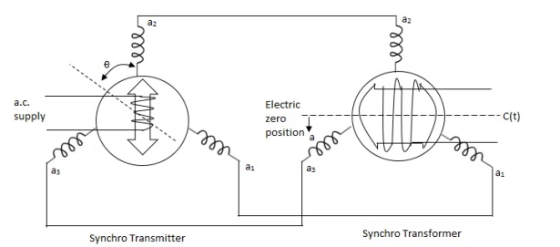
Let transmitter rotate at an angle ϴ and control transformer rotor rotate in same direction through α. Then,
φ = ( 90 - ϴ + α )
Voltage across rotor terminal is given as,
e(t) = K1Vrcos ϴSinwot
e(t) = K1VrSin(ϴ - α) Sin wot
From above equation we can conclude that when two rotor shafts are not aligned, the rotor voltage of transformer is a sine function of difference between two angles.
For small angular displacement between two rotor position,
e(t) = K1Vr(ϴ - α)Sinwot
Analogy Between Electrical and Mechanical System:
Force -voltage | Force -current | Mechanical Translatory | Mechanical Rotational |
1.Voltage (v) | Current | Force (f) | Torque (T) |
2.Charge(q) | Flux (ø) | Displacement(x) | Angular Displacement(ø) |
3.current. | Voltage | Velocity v(t) | Angular velocity(w) |
4.Inductance(l) | Capacitance(c) | Mass (m) | Moment of inertia (J) |
5. Resistance(R) | Conductance G= (1/R) | Damping coefficient (B) | Damping Coefficient (B) |
6.Reciprocal of capacitance(1/c) | Inverse of Inductance (1/L) | Stiffness (K) | Stiffness(K) |
Generally, a function can be represented to its polynomial form. For example,
F(s) = f0sn + f1sn -1 +f2sn – 2 + f3sn – 3 + . . . + fn – 1s1 + fn
Now similarly transfer function of a control system can also be represented as


Where K is known as the gain factor of the transfer function.
Now in the above function if s = z1, or s = z2, or s = z3,….s = zn, the value of transfer function becomes zero. These z1, z2, z3,….zn, are roots of the numerator polynomial. As for these roots the numerator polynomial, the transfer function becomes zero, these roots are called zeros of the transfer function.
Now, if s = p1, or s = p2, or s = p3,….s = pm, the value of transfer function becomes infinite. Thus, the roots of denominator are called the poles of the function.
The transfer function of system is ratio of output to the input.
References:
1. Automatic Control Systems, Benjamin. C. Kuo, Prentice Hall of India, 7th Edition,1995.
2. Digital Control and State Variable Methods, M. Gopal, 2nd Edition, TMH, 2007.
3. Feedback and Control Systems, Stubberud, Schaum’s Outline Series, TataMcGraw-Hill, 2007.
4. Linear Control System Analysis and Design, John J. D’azzo & Constantine H.Houpis, Tata McGrow-Hill, Inc., 1995.
5. Modern Control Systems, Richard C. Dorf & Robert H. Bishop, Addison –Wesley, 1999.
Unit – 1
Control System controls
Hydraulic
The Hydraulic system of interest to control engineers may be classified into,
1.Liquid Level system
2.Hydraulic devices
The liquid level system consists of storage tanks and connecting pipes. The variables to be controlled are liquid height in tanks and flow rate in pipes. The driving force is the relative difference of the liquid heights in the tanks. The Hydraulic devices are devices using incompressible oil as their working medium. In this we will be learning transfer function of hydraulic system.
These devices are used for controlling the forces and motions. The driving force is the high-pressure oil supplied by the Hydraulic pumps. Liquids are slightly compressible at high pressures.
In hydraulic system, the compressibility effects may be neglected and conservation of volume is used as the basic physical law. The variables of hydraulic system are volumetric flow rate, q and pressure, R The volumetric flow rate, q is through variable and it is analogous to current. The pressure, P is across variable and it is analogous to voltage.
Three basic elements of hydraulic systems are the Resistance, Capacitance and inertance. The liquid flowing out of a tank can meet the resistance in several ways. Liquid while flowing through a pipe meet with resistance due to the friction between pipe walls and liquid. Presence of valves, bends, coupling of pipes of different diameter also offer resistance to liquid flow.
The capacitance is an energy storage element and it represents storage in gravity field. The inertance represents fluid inertia and is derived from the inertia forces required to accelerate the fluid in a pipe. It is also an energy storage element. But the energy storage due to inertance element is negligible compared to that of capacitance element.
Servomotors: These motors are used in feedback control system. These are also known as control motors. These motors should have low rotor inertia and high speed of response. The servomotors used in the feedback control systems should have linear control signal and rotor speed.
Types of Servomotors:
(a). A.C. Servomotors
(b). D.C. Servomotors
(a). A.C. Servomotors:
A.C servomotor is a two-phase ac induction motor. There are two windings in this motor, one is fixed or reference winding is supplied with a fixed voltage and frequency from a constant voltage source. Second winding is control winding with variable supply voltage of same frequency as reference winding but having a phase displacement of 900 electrical. A flux is induced due to the phase change which cuts the conducting bars of rotor and causes a time varying current, this current produces a time varying flux and reacts with the stator flux causing the rotor to rotate.
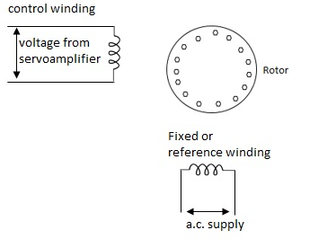
Fig 1. AC Servomotor
The rotor of A.C. Servo motors are of two types,
(a). Squirrel Cage Rotor
(b). Drag cup type rotor
(a). Squirrel cage rotor: They have high resistance as the rotor is having large length and small diameter. The air gap here is kept small.

Fig 2. Squirrel cage rotor
(b). Drag cup type motor: For the drag cup rotor there are two air gaps. For the rotor a cup of non-magnetic conducting material is used. A stationary iron core is placed between the conducting cup to complete the magnetic circuit. The resistance of drag cup type is high and therefore, has high starting torque. Generally aluminium is used for cup.
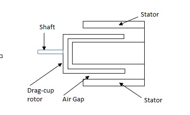
Fig 3. Drag Cup type rotor
Torque-speed characteristic:
The torque speed characteristics of the two phase servomotor depends on ratio of reactance to resistance(X/R).
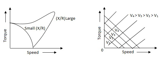
Fig 4. The torque speed characteristics of the two phase servomotor
(i). For high ‘R’ and low X, the characteristic is linear and
(ii). For high X and low R, it becomes non-linear.
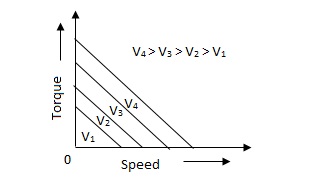
Fig 5. Torque-speed characteristic for various voltage
The torque-speed characteristic for various voltage is almost linear.
(b). D.C. Servomotor:
D.C. Servomotor are separately excited or permanent magnet dc servomotors. The armature of D.C. Servomotors is having large resistance and hence torque-speed characteristic is linear.
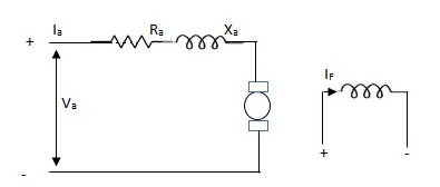
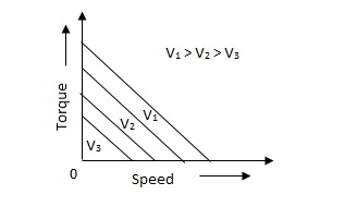
Fig 6. (a) DC Servomotor (b) Torque-speed characteristics
The above graph fig (b), clearly shows that the torque-speed characteristics is a function of control winding voltage as shown below.
T = mw + KVc -- (1)
Where T = Torque developed by motor
w = angular velocity
Vc = control winding voltage
Taking laplace of above equation (1),
T(S) = mS Q(S) + KVc - - (2)
T(S) = JS2Q(S) + FSQ(S) - - (3)
Above equation(3) is the dynamic equation with,
J – moment of inertia
F – coefficient of friction of motor
From equation (2) and (3) the block diagram will be,

Fig 7. Block Diagram of DC Servomotor
Q(S)/Vc = K/Js + F + m - - (4)
Key takeaway
Comparison between A.C. Servomotor & D.C. Servomotor
| A.C. Servomotor | D.C. Servomotor |
|
|
|
1. | They are less efficient | They are more efficient |
2. | They have low power output | They have high power output |
3. | No noise so has smooth operation | These motors have noisy operation |
4. | They do not have any radio frequency noise | These motors have brushes so produce radio frequency noise |
5. | They are maintenance free because of no brushes and slip rings | For these motors, maintenance is required. |
Consider the flow through a short pipe connecting two tanks. The Resistance, R for liquid flow in such a pipe or restriction, is defined as the change in the level difference, necessary to cause a unit change in the flow rate.
R = Change in level difference/Change in flow rate
The Capacitance, C of a tank is defined to the change in quantity of stored liquid necessary to cause in the potential (head).
C = Change in liquid stored/Change in head
A simple liquid level system is shown in the below figure with steady flow rate, Q and steady state head, H.
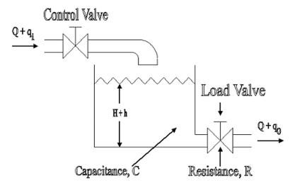
Fig 8. Liquid Level System
Let Q = Steady state flow rate(before any change has occured)
Qi = Small deviation of inflow rate from its steady-state value
Qo = Small deviation of outflow rate from its steady-state value
H = Steady state head (before any change has occurred)
h = Small deviation of head from its steady state value
Let the system be considered linear. The differential equation governing the system is obtained by equating the change in flow rate to the amount stored in the tank. In a small time interval dt, let the change in flow rate be (qi - qo) and the change in height be dh.
Now, Change In storage = Change in flow rate
C dh = (qi - qo) dh

Qo = h/R
On substituting for qo, we get,
 RC dh/dt + h = qi R
The above equation is the differential equation governing the system. The term RC is the time constant of the system .On the Laplace's transform of above equation we get,


The above equation is the required transfer function of the Hydraulic system.
- Collection of components which allows to follow the desired course.
- In a car: ensure that wheels are pointing in the desired direction of motion.
- Convert rotary motion of the steering to the angular turn of the wheel.
- Mechanical advantage is used in this case.
- The joints and the links should be adjusted with precision.
- Smallest error can be dangerous
- Mechanism should not transfer the shocks in the road to the driver's hands.
- It should minimize the wear on the tyres.
RACK AND PINION STEERING SYSTEM
- The pinion moves the rack converting circular motion into linear motion along a different axis
- Rack and pinion give good feedback there by imparts a feel to the driving
- Most commonly used system in automobiles now.
- Disadvantage of developing wear and there by backlash.
RECIRCULATING BALL
- Used in Older automobiles
- The steering wheel rotates the shaft which turns the worm gear.
- Worm gear is fixed to the block and this moves the wheels.
- More mechanical advantage.
- More strength and durable
POWER STEERING
- Too much physical exertion was needed for vehicles
- External power is only used to assist the steering effort.
- Power steering gives feedback of forces acting on the front wheel to give a sense of how wheels are interacting with the road.
- Hydraulic and electric systems were developed.
- Also, hybrid hydraulic-electric systems were developed.
- Even if the power fails, driver can steer only it becomes heavier.
ELECTRIC POWER STEERING
- Uses an electric motor to assist the driving
- Sensors detect the position of the steering column.
- An electronic module controls the effort to be applied depending on the conditions.
- The module can be customised to apply varying amounts of assistance depending on driving conditions.
- The assistance can also be tuned depending on vehicle type, driver preferences
Generally, there are three types of EPS systems: column-type, rack-type and pinion type. The selection of different configurations depends on the package and in-vehicle environment.
The schematic arrangement of a column-type EPS system is shown in figure
The EPS consists o f a torque sensor, which senses the driver’s movements of the steering wheel as well as the movements of the vehicle; an ECU, which performs calculations on assisting force based on signals from the torque sensor; a motor, which produces turning force according to the output from ECU; and a reduction gear, which increases the turning force from the motor and transfers it to the steering mechanism. The rest of the steering system: Steering Wheel (or hand wheel, HW), Intermediate Shaft (IShaft), and Rack & Pinion are also shown. Basically, the control procedure can be summarized as follows:
1) The torque sensor estimates the torque, which is the command from the human to steer the car, by the torsion bar mechanism inside.
2) ECU calculates the assistant torque based on the command torque (from torque sensor), the vehicle speed (from speed sensor or in-vehicle network) and the status of the electric motor, and then sends the command to the electric motor.
3) The electric motor generates the assistant torque according to the command from the ECU and transfers it to the column through a worm gear mechanism.
4) With the power assistance from the electric motor, the pinion and rack turns the wheels.
STEERING WHEEL DYNAMIC MODEL
The upper part of the system model is the dynamic model o f the human wheel. The MatLab model is as follows:

The differential equation of the steering wheel is:
Th – Ts = Jhw  + Bhw
+ Bhw  + Bhw
+ Bhw  + Khw θhw
Where 7/, and Ts are the torque from driver and torque sensor, respectively. 8hw denotes the angle o f rotation of the steering wheel. Jhw, Bhw and Khw are moment of inertia, damping coefficient and stiffness coefficient. To simplify the model, the stiffness coefficient can be neglected. That is to say, the steering wheel is rigid connection. The dynamic model can be simplified as follows:


THE DYNAMIC MODEL OF PINION AND RACK ASSEMBLY
The pinion and rack are modeled as a mechanic system consists of a mass and a spring. The differential equation of the steering wheel is:
Tr + Tf = Jr  + Br
+ Br  + Kr θ
Where Jr, Br and Kr are the moment of inertia, damping coefficient and stiffness coefficient, respectively. Tr and Tf denote torque from road wheels and steering torque, respectively. 6 represents the road wheel position. The model of the pinion and the rack is as follows

Both of the force torque and the road torque have the same positive direction. Also, to simplify the system, the stiffness coefficient is assumed to be zero. As a result, the model can be simplified as follows

A manipulator is a mechanical system formed by the connection of a set of rigid bodies, links, through joints. Joints provide each pair of connected links with some freedom of relative motion. The description of the spatial location of a rigid body is therefore the basis for the spatial description of a manipulator. The configuration of a rigid body is a description of its position and orientation. The position of a rigid body is determined by a description of the position of an arbitrary point attached to the rigid body. The orientation of a rigid body is determined by the description of its rotations about this point.
Position of a Point
Let us consider a point P of an Euclidean affine space E, where an arbitrary point O has been selected as the origin. The position of P is given by the vector p =  P. With respect to O, the positions of points: P1, P2,..., Pn are described by the vectors: p1 =
  P1, p2 =
  P2,..., pn =
  Pn.
Pn.
For points of the 3-dimensional space, positions are described by vectors p ∈ R3. Let {x, y, z} be an orthonormal basis of R3. The components of a vector p with respect to this basis are identical to the coordinates of P given with respect to the coordinate frame R (O, x, y, z).
Taking the components of the vector p with respect to another orthonormal basis {x’, y’, z’} correspond to a representation of P in a coordinate frame having the same origin, O, and using the unit vectors x’, y’, z’, i.e. R’ (O, x’, y’, z’), as shown in Figure. The relationship between these two representations is given by the base transformation or the coordinate transformation between the two frames of same origin.
Rotation Transformation
Rotation transformations are transformations that operate on the unit vectors of coordinate frames, while conserving the frame origins. These transformations are equivalent to transformations between orthonormal bases. A rotation transformation is defined by the relationships between the unit vectors of two coordinate frames. The rotation transformation between R (O, x, y, z) and R’ (O, x’, y’, z’), of identical origin O, is described by a 3 × 3 orthonormal rotation matrix S. The columns of S are the components of the three-unit vectors x’, y’, and z’ expressed in the coordinate frame R.
S = (x’(R) y’(R) z’(R))
S-1 = ST
The rows of S define, therefore, the components of the three unit vectors x, y, and z expressed with respect to the coordinate frame R’.
A manipulator is treated as a holonomic system with a structure of an open kinematic chain of n+1 rigid bodies, i.e., links, articulated through n revolute and/or prismatic joints having one degree of freedom.
The kinematic relationship between a pair of adjacent links in the chain is described by the coordinate transformation between two coordinate frames attached to the two links. Links are numbered from 0, the base, to n, the end-effector, while joints are numbered from 1 to n
A coordinate frame Ri (Oi, xi, yi, zi) is attached to link i. The position and orientation of the link i with respect to link i−1 is described by the transformation between a coordinate frame Ri−1(Oi−1, xi−1, yi−1, zi−1) attached to the link i − 1 and Ri
Parameters of Denavit-Hartenberg
The kinematic relationship between a pair of adjacent links i − 1 and i connected through a one-degree-of-freedom joint i can be completely determined by a set of four parameters (αi, ai, θi, ρi), called parameters of Denavit-Hartenberg. These parameters define the homogeneous transformation between the two coordinate frames attached to the two links. With the convention shown in Figure, the Denavit-Hartenberg parameters are defined as
αi: the angle between the z-axes of Ri and Ri+1, measured1 about xi;
ai: the length of the common normal to the z−axes of Ri and Ri+1, measured along xi;
θi: the angle between the x-axes of Ri−1 and Ri measured about zi.
ρi: the distance between the x-axes of Ri−1 and Ri measured along zi.

Measuring instruments are used to measure a quantity. When choosing an instrument, the static calibration and static performance of an instrument must be considered
The characteristics of measuring instruments can be classified into the following categories:
1)Static performance characteristics
2)Dynamic performance characteristics
Static calibration refers to the procedure where an input is constant or a variable is applied to an instrument. Instruments are manufactured based on the property of irreversibility or directionality. This implies that change in an input quantity will cause a corresponding change in the output. A calibration standard must be at least ten times more accurate than the instrument to be calibrated.
Static performance characteristics include the linearity performance of the instrument, static sensitivity of the instrument, repeatability of the same results, hysteresis resolution, and the readability of the results.
Static performance characteristics influence data acquisition if the instruments are not properly calibrated prior to the measurement. Understanding quality control and quality assurance procedures for handling equipment is essential for the PE exam.
Linearity
If the relationship between the output and input can be expressed by the equation Q0= P + RQ1, where P and R are constants, then the instrument is considered linear. Linearity is never fully achieved in real-world situations, and the deviations from the ideal are referred to as linearity tolerances. For example, 3% independent linearity means that the output will remain within the values set by two parallel lines spaced ± 3% of the full-scale output from the idealized line. If the input-output relationship is not linear for an instrument, it may still be approximated to a linear form when it is used over a very restrictive range.
Static Sensitivity
Static sensitivity can be defined as the slope of a calibration curve.
Sensitivity = Q0/Q1
Sensitivity influences the input parameters of an instrument. The sensitivity factor can also be referred to as sensitivity drift or scale factor drift.
Repeatability Error
When an instrument is used to measure the same or an identical input many times and at different time intervals, the output is never the same; it deviates from the recorded values. This deviation from the ideal value is referred to as repeatability error.
Hysteresis-Threshold Resolution
When testing an instrument for repeatability, it is often noted that the input-out value does not coincide with the inputs, which are continuously ascending and descending values. This occurs because of hysteresis, which is caused by internal friction, sliding, external friction, and free play mechanisms. Hysteresis can be eliminated by taking readings corresponding to the ascending and descending values of the input and calculating their arithmetic mean.
Professional engineers who work with measurements and instrumentation should understand calibration procedures of various instruments for proper data acquisition.
Machine Tools
Computer Integrated Manufacturing (CIM) encompasses the entire range of product development and manufacturing activities with all the functions being carried out with the help of dedicated software packages. The data required for various functions are passed from one application software to another in a seamless manner.
For example, the product data is created during design. This data has to be transferred from the modeling software to manufacturing software without any loss of data. CIM uses a common database wherever feasible and communication technologies to integrate design, manufacturing and associated business functions that combine the automated segments of a factory or a manufacturing facility. CIM reduces the human component of manufacturing and thereby relieves the process of its slow, expensive and error-prone component.
CIM stands for a holistic and methodological approach to the activities of the manufacturing enterprise in order to achieve vast improvement in its performance. This methodological approach is applied to all activities from the design of the product to customer support in an integrated way, using various methods, means and techniques in order to achieve production improvement, cost reduction, fulfilment of scheduled delivery dates, quality improvement and total flexibility in the manufacturing system.
CIM requires all those associated with a company to involve totally in the process of product development and manufacture. In such a holistic approach, economic, social and human aspects have the same importance as technical aspects. Manufacturing industries strive to reduce the cost of the product continuously to remain competitive in the face of global competition.
In addition, there is the need to improve the quality and performance levels on a continuing basis. Another important requirement ison time delivery. In the context of global outsourcing and long supply chains cutting across several international borders, the task of continuously reducing delivery times is really anarduous task. CIM has several software tools to address the above needs. Manufacturing engineers are required to achieve the following objectives to be competitive in a global context.
• Reduction in inventory
• Lower the cost of the product
• Reduce waste
• Improve quality
• Increase flexibility in manufacturing to achieve immediate and rapid response to:
• Product changes
• Production changes
• Process change
• Equipment changes
• Change of personnel
Basic components of NC system
1.Input medium
2.MCU
3.Machine Tool
Basic Components of an NC System and NC system consists of three basic components:
Program of instructions: The detailed step-by-step commands that direct the actions of the processing equipment. In machine tool applications, the program of instructions is called a part program, and the person who prepares the program is called a part programmer. In these applications, the individual commands refer to positions of a cutting tool relative to the worktable on which the workpart is fixtured. Additional instructions are usually included, such as spindle speed, feed rate, cutting tool selection, and other functions. The program is coded on a suitable medium for submission to the machine control unit. (2) Machine control unit MCU: Consists of a microcomputer and related control hardware that stores the program of instructions and executes it by converting each command into mechanical actions of the processing equipment, one command at a time. The related hardware of the MCU includes components to interface with processing equipment and feedback control elements. The MCU also includes one or more reading devices for entering part programs into memory. The MCU also includes control system software, calculation algorithms, and translation software to convert the NC part program into a usable format for the MCU. Submission to the machine control unit.
(2) Machine control unit MCU: Consists of a microcomputer and related control hardware that stores the program of instructions and executes it by converting each command into mechanical actions of the processing equipment, one command at a time. The related hardware of the MCU includes components to interface with processing equipment and feedback control elements. The MCU also includes one or more reading devices for entering part programs into memory. The MCU also includes control system software, calculation algorithms, and translation software to convert the NC part program into a usable format for the MCU.
Prime movers
The actual meaning of prime mover is a primary source of power. It means all the machinery that provide power for performing different mechanical work. Technically, it is a group of machines that transform energy from thermal, electrical or pressure into mechanical form for use in different sources for some mechanical work. Engines and turbines are examples.
The prime movers are listed based on the sources of energy utilized by them.
A. Thermal prime movers These are the prime movers which use the thermal energy of source to produce power. Different thermal prime movers are given below: -
Fuels (Heat engines): - These prime movers use several fuels like petrol, diesel, oil, gas to produce mechanical power. Heat engines are two types: -
1. External combustion engines: -Reciprocating steam engines Steam turbine Closed cycle gas turbine
2. Internal combustion engines: -Reciprocating I.C. Engines Open cycle gas turbine
- Nuclear (Nuclear power plant): - This prime mover utilises the heat energy of atoms by fission or fusion method to develop the mechanical power. It is chiefly used in nuclear power plants. Different radioactive components like uranium, thorium is used for these fission or fusion process in a nuclear reactor.
- Geothermal: - In this kind of prime mover the heat energy is recovered from a certain depth or the hot part of the earth beneath earth surface then it is transformed into mechanical by the proper engine.
- Biogas: - Biogas is principally produced from garbage or any other waste which is used to generate power by the prime mover in a biogas plant.
- Solar energy: - The solar energy spread to the earth in the form of radiation or electromagnetic waves. This energy trapped in with the help of solar panel made up of semiconductor element. This heat energy is then turned into power.
B. Non-thermal prime movers: - These kinds of prime movers do not use the heat energy to transform it into mechanical power. The following are the non-thermal prime movers:
- Hydraulic turbines: - This kind of prime mover uses the stored potential energy of water to generate power.
- Wind power: - With the help of the wind turbine, wind energy is transformed into power.
- Tidal power: - The energy of tides from the ocean is transformed into power by the use of the turbine which is known as tidal power.
System generators
System Generator is a powerful tool that integrates Xilinx FPGA design process with MATLAB’s Simulink which uses a high-level description to easily realize a complex system. We first design the system and verify its functionality in the Simulink environment. The graphical high-level description of Simulink significantly facilitates modeling, simulating, and analysing the design.
A control system is a set of mechanical or electronic devices which control the other devices. In control system behaviours of the system is desired by differential equations.
The above figure shows a feedback system with a control system. The components of control system are:
i) The actuator takes the signal transforms it accordingly and causes some action.
Ii) Sensors are used to measure continuous and discrete process variables.
Iii) Controllers are those elements which adjust the actuators in response to the measurement.
Open loop systems:
This is the loop of control system without any feedback. In this the control action is not dependent on the desired output.

Fig. 9 open loop control system
Example of open Loop systems are the traffic signals, Automatic washing machine and in fields control d.c. Motor.
G(s) = c(s)/R(s) -------(1)
Closed loop systems:
This is a type of control system with feedback. In this type of system. The control action is dependent on the desired output.

Fig 10. Closed Loop control system
The error signal is again fed to controller to the error and get desired output.
G(s) – forward amplification
H(s) _ Reverse amplification
Above system is with negative feedback.
Positive feedback is used only in oscillators and other use is not known as discussing only negative feedback.
[ R(s) – c(s) H (S) ] G(s) = c(s)
R (s) G(s) = [1+G(s) H(s)] c(s)
C(s)/R(S) = G(S)/1+G(s) H(s)
So, the transfer function of closed Loop system is
C(s)/ R(S) = G(s)/ 1+G(S) H(S) --------(2)
If numerator of above equation (2) is equalized to zero we get zeros of closed Loop Transfer function [G(S) = 0]
If dominator of equation (2) is equaled to zero we get polls of the closed loop transfer function [ 1+G(s) H(S) = 0]
1+ G(S) H(s) = 0 [ characteristic Equation]
Stability of the system is determined by the location of its poles.
Comparisons between open Loop and Closed Loop system
Open Loop System | Closed Loop system |
1.It does Not have any feedback. | 1. This system comprise of feedback |
2.As no feedback so easier to build. | 2.As it has feedback so difficult to build |
3.Theaccuracy of this system depends on the calibration of input. | 3.They are accuracy because of the feedback. |
4.Open Loop system are more stable. | 4.In closed Loop system stability depends on system components. |
5.optimization is not possible | 5. Optimization is possible |
6.These systems are not reliable. | They are more reliable |
Example 1. For the circuits given below write the voltage equations:
Solution: Let current i1be in loop 1 current and i2 for loop 2


Que. Write the loop equations for the given circuit below?
Solution:
For loop 1

For loop 2

Q) Write the integro-differential equation for the loop currents shown below.

Sol: Equation for loop 1 with current i1
v(t)=(R1+R2+R4)i1 +L -R2 i2+ R5i3
Equation for loop 2 with current i2
-R2i1+(R2+R3) i2 + +R3i3 = 0
Equation for loop 3 with current i3
V(t) = R1i3+R3i3+(R1+R3+R5) i3+
Q) For the given network write the integro differential equation?
Sol: Let V1 and V2 be the node voltages.
Equation for node v1 will be
 +
+ +
+ +C1
+C1 = i1
= i1
 + C2
+ C2 + C1
+ C1 +
+ = i2
= i2
It is a technique for solving differential equations. The time domain differential equations are transformed into algebraic equation of frequency domain. After solving the algebraic equation in frequency domain, the result then is finally transformed to time domain form to achieve the ultimate solution of the differential equation.
The Laplace Transform is given as
F(s)= dt
dt
The advantages of Laplace Transform are:
1) It is systematic.
2) It gives total solution (transient and sustained solution) in one operation.
3) The initial conditions are automatically specified in the transformed equations.
There are many functions which do not have Laplace Transforms. These functions are not generally used in analysis of linear systems. But some conditions can be defined to get Laplace transformation of such functions. The Dirichlet condition defines the necessary condition for transformation of some functions such as:
a) The function should be continuous. The function should be single-valued.
b) The function must be of exponential order.
Properties of Laplace Transform:
1) Linearity Property:
If f1(t) and f2(t) are two functions of time. Then, in domain of convergence
L[a f1(t)+b f2(t)]=a + b
+ b
=aF1(s)+bF2(s)
2) Differentiation Property:
If x(t) is function of time then Laplace transform of nth derivative is given as


3) Integration Property:
The Laplace of nth order integral is given as
L[ ]=
]= +
+
L[f-n(t)]= +
+ +
+ +……….
+……….
As  ……..=0. Hence
L[f-n(t)]=
Laplace Transform of Basic R, L and C components
LAPALACE TRANSFORM:
If LT[f(t)]= F(s)
Where F(s)= dt
dt
f(t) F(s)
F(s)
 sF(s)-f(0-)
 f(t)
f(t) S2F(s)-sf(0-)-f’(0-)
Now, we find Laplace for 
 =
= +
+
Now if f(t)=ic(t) [current through capacitor]
 =
= +
+
 =
= +
+
=[q(0)-q( )]+
)]+
=[q(0)-0]+
Multiplying both sides by 1/C
 =
= +
+
Vc(t)= +
+
Vc(t)=Vc(0)+
By Laplace Transform
Vc(s)= +
+
Vc(s)= +
+

Fig 11. Laplace transformed circuit for C
Now by source conversion
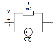
Fig 12 .Source transformed circuit for C
 =
= +
+
Now if f(t)=VL(t) [voltage across inductor]
 =
= +
+
 =
= +
+
= -
- ]+
]+
= -0]+
-0]+
Multiplying both sides by 1/L
 =
= +
+
iL(t)=iL(0)+
By Laplace Transform
IL(s)= +
+
IL(s)= +
+
NOTE: Voltage------->Series circuit
Current------->Parallel circuit

Fig 13. Laplace transformed circuit for L
By source transformation

Fig 14. Source transformed circuit for L
Current through capacitor
iC(t)=
IC(s)=C[sVc(s)-Vc(0)]
Vc(s)= +
+
Voltage about inductor,
VL(t)=
VL(s)=L[sIL(s)-iL(0)]
IL(s)= +
+
It is the ratio of Laplace transform of the output to Laplace transform of input with all initial conditions zero.

Fig 15. System with Transfer Function G(s)
Poles and zero of a Transfer Function:
The transfer function can be represented by the ratio of two polynomials
G (S) = a0sn+a1 sn-1-------+an/b0sm+b1sm-1+-----+bn
a0—an ---- constants
G(S) = K(s+z1) (s+z2) (as2+bs+c)/(S+A) (s+p2) (As2+Bs +c)
K= a0/b0 ( Gain of system)
For poles –They are the values of s for which
G(S)
(S+p1)(S+p2)(AS2 + BS + C) = 0
S= p1, -p2 , -B±B2-4Ac/2A
For ZEROS – They are the values of s for which
G(S)0
S=-z1, -z2 , -b±b2-4ac/2a
- Location of poles and zeros in s place determines the reliability of the system
- There can be multiple poles and zeros
- The numerator of transfer function when equalized to zero gives zero of system
- The denominator of transfer function which equalized to zero gives poles of system.
Key takeaways
- The numerator of transfer function when equalized to zero gives zero of system.
- The denominator of transfer function which equalized to zero gives poles of system.
Mechanical System
(a) Translational system
(b) Rotational system
(a) Translational system
The motion that takes place along a straight line is called translational motion. The forces that resist motion are -
Inertia: A body with mass ‘N’ acceleration ‘a’ will produce inertia fm(t)= malt N’ acceleration ‘a’ will produce inertia
fm(t)= M a(t)
In terms of velocity
Fm(t) = M dv(t)/dt
In terms of displacement
Fm(t)= Md2/dt2µt
Damping force: The damping force is proportional to velocity for vis case function
F0(t) = B(t) = B dx(t) /dt
B Damping coefficient N/M sec
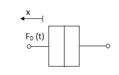
Fig 16. Damping force
Spring force: A spring stores potential energy. The releasing force of a string is proportional to the displacement.
Fk(t)  x(t)
x(t)
Fk(t) = k x (t)
Fk(t) = k 
K = string constant N/m.

Fig 17. Spring force
Fk(t) = k 
K = string constant N/m.
(b) Rotational system:
The motion of a body about a fixed axis is called as Rotational motion. The types of torques which can resist the motion are
Inertial Torque: The inertial torque is the product of moment of inertia I and angular acceleration.
TI(t) = J (t)
(t)
TI(t) = Jd/dt w(t)
TI(t) = Jd2ø(t)/dt2(N-m)
W (t) – Angular velocity
Ø(t) = Angular displacement
Damping Torque: It is product of damping efficient B and angular velocity w
T0 (t) = B w(t)
T0(t) = B d/dt ø(t)
Spring Torque: It is the product of torsional stiffness and angular displacement
Tø(t) = k ø(t)
K = N.m/rad
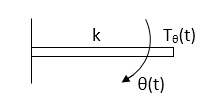
Fig 18. Spring Torque
D’Alembert’s Principle
For anybody, the algebraic sum of externally applied forces and the forces resisting motion in any given direction is zero.
Ex.
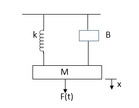
In above figure applying D’Alemberts principle to write the equation of motion
As force f(t) acts downwards all other forces (of k,B,x) acts Opposite to it to considering f(t) as the and all other forces negative.
F(t)+fm (t) + fD(t) +fx(t) =0
f(t)- M d2x(t)/dt2+B dx(t)/dt +x(t)
Example
Q.1 Draw the free body diagram and write the differential equation for system below.

Fig 19. Mechanical system
Sol: The free body diagram for M1 will be
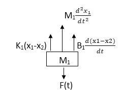
Fig 20. FBD
F(t) = M1 d2/dt2x1+ B1 d/dt (x1-x2)+ k1(x1-x2)
Similarly for M2we have
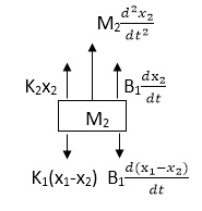
Fig 21. FBD
K1(x1-x2) + B1d/dt(x1-x2) = k2x2+M2d2/dt2+B2dx2/dt
Electrical System
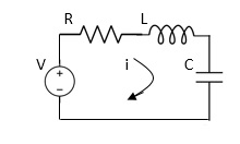
Fig 22. RLC Circuit
Example-1 For circuit shown above find value of current I?
Applying Kirchoff’s voltage Law
V= Ri +Ldi/dt +1/c
V= Rdq/dt + L d2q/dt2+q/c
Now By kirchoff’s current low
I= V/R+ 1/L  + cdv/dt
But V= dø/dt
I= 1/R dø/dt + 1/L ø+cd2ø/dt2
But v= dø/dt
I= 1/R dø/dt+ 1/L. ø+c d2ø/dt2
Example-2 For the given mechanical system below draw the analogus system (force. Voltage )& find V0(s)/V1(s)
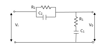
Soln.
Let Z1 = R2 11 1/c2
=R2*1/c2s/R2+1/c2s
Z1= R2/1+R2c2s
Let Z2 = R1+1/c1s
Z2= 1+R1c1s/c1s
V0(s)/vi(s) = z2/z1+z2
=1+R1c1s/c1s/R2/1+R2c2s+1+R1c1s/c1s
V0(s)/v0(s) =(c1+R1c1s) (1+R2c2s)/R2c1s+1+sR1c1s2R1R2c1c2
Electronic system and Electro-mechanical system.
Stepper Motors
It is a device whose output is completely controlled by the input pulses. There are two types of stepper motors:
a) Variable Reluctance
b) Permanent Magnet
A variable reluctance stepper motor consists of stator having a common frame and rotate n a common shaft. Rotor and stator have toothed structure and teeth are of same size so that it can be aligned on same axis. The stator re pulse excited while the rotor is unexcited. When stator is excited stator and rotor teeth are aligned to minimum reluctance position. The stator torque of the rotor depends on the displacement  .
.
There are two positions of zero torque:
i) For  =0 when rotor and stator are aligned is called stable position because slight disturbance from this position in either direction brings the rotor back to its original position.
Ii) For  = 180/T when tooth and stator are aligned is called unstable position. This is because of slight disturbance from this position in either direction makes the rotor move away from it.
For multiple stack stepper motor, Step angle  = 360/nxT
n: number of stacks
T: number of rotor teeth
These motors are used in computer peripherals.
Tacho Generators
These are electromechanical devices which convert mechanical input at their shaft to corresponding electrical output. It is basically used to measure speed of motor. It has negative feedback. These devices are most commonly used to find speed of any rotating machine.
| D.C. Tachometer | A.C. Tachometer |
1. | They convert rotational speed into a proportional dc voltage. | They convert the rotational speed into a proportional ac voltage. |
2. | It uses a permanent magnet for producing magnetic field. It contains iron core rotor. | It works on principle of induction generator. |
3. | The permanent magnet controls the magnetic field therefore the induce voltage at terminal of armature is proportional to shaft speed. | The reference winding is supplied by reference voltage and the output voltage is induced across the output winding. |
4. | The polarity depends on direction of rotation. | The amplitude and phase depends on the direction of rotation. |
Synchros
Its construction is similar to a three-phase alternator. The stator is made of laminated silicon steel and rotor is dumbbell shaped magnet with a single winding.
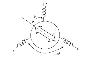
Let the applied a.c. Voltage to the rotor is,
er = ErSinwot
Let the rotor be at angle of ϴ, then voltage in each stator coil with respect to neutral,
Ean = KErSinwot cos(ϴ)
Ebn = KErSinwotcos(ϴ + 1200)
Ecn = KErSinwotcos(ϴ + 2400)
Magnitude of stator terminal voltage,
Ecb = Ecn – Ebn
= KErSinwot[cos(ϴ + 2400) – cos(ϴ + 1200)]
= KErSinwot(√3 Sinϴ)
Ecb = √3KErSinwot Sinϴ
Similarly,
Eac = √3KErSinwot Sin(ϴ + 1200)
Eba = √3KErSinwot Sin(ϴ + 2400)
When ϴ = 0, Ecb, Ean = 0
Hence, input to the synchro transmitter is the angular position of motor shaft and output are three phase voltage which are function of shaft position.
Synchro Transformer
Its basic working principle is similar to the synchro transformer. Here the rotor is cylindrical type. It is an electromechanical device. The combination of synchro transmitter and synchro transformer is used as an error detector.
The basic diagram is shown below

Let transmitter rotate at an angle ϴ and control transformer rotor rotate in same direction through α. Then,
φ = ( 90 - ϴ + α )
Voltage across rotor terminal is given as,
e(t) = K1Vrcos ϴSinwot
e(t) = K1VrSin(ϴ - α) Sin wot
From above equation we can conclude that when two rotor shafts are not aligned, the rotor voltage of transformer is a sine function of difference between two angles.
For small angular displacement between two rotor position,
e(t) = K1Vr(ϴ - α)Sinwot
Analogy Between Electrical and Mechanical System:
Force -voltage | Force -current | Mechanical Translatory | Mechanical Rotational |
1.Voltage (v) | Current | Force (f) | Torque (T) |
2.Charge(q) | Flux (ø) | Displacement(x) | Angular Displacement(ø) |
3.current. | Voltage | Velocity v(t) | Angular velocity(w) |
4.Inductance(l) | Capacitance(c) | Mass (m) | Moment of inertia (J) |
5. Resistance(R) | Conductance G= (1/R) | Damping coefficient (B) | Damping Coefficient (B) |
6.Reciprocal of capacitance(1/c) | Inverse of Inductance (1/L) | Stiffness (K) | Stiffness(K) |
Generally, a function can be represented to its polynomial form. For example,
F(s) = f0sn + f1sn -1 +f2sn – 2 + f3sn – 3 + . . . + fn – 1s1 + fn
Now similarly transfer function of a control system can also be represented as


Where K is known as the gain factor of the transfer function.
Now in the above function if s = z1, or s = z2, or s = z3,….s = zn, the value of transfer function becomes zero. These z1, z2, z3,….zn, are roots of the numerator polynomial. As for these roots the numerator polynomial, the transfer function becomes zero, these roots are called zeros of the transfer function.
Now, if s = p1, or s = p2, or s = p3,….s = pm, the value of transfer function becomes infinite. Thus, the roots of denominator are called the poles of the function.
The transfer function of system is ratio of output to the input.
References:
1. Automatic Control Systems, Benjamin. C. Kuo, Prentice Hall of India, 7th Edition,1995.
2. Digital Control and State Variable Methods, M. Gopal, 2nd Edition, TMH, 2007.
3. Feedback and Control Systems, Stubberud, Schaum’s Outline Series, TataMcGraw-Hill, 2007.
4. Linear Control System Analysis and Design, John J. D’azzo & Constantine H.Houpis, Tata McGrow-Hill, Inc., 1995.
5. Modern Control Systems, Richard C. Dorf & Robert H. Bishop, Addison –Wesley, 1999.
Unit – 1
Control System controls
Hydraulic
The Hydraulic system of interest to control engineers may be classified into,
1.Liquid Level system
2.Hydraulic devices
The liquid level system consists of storage tanks and connecting pipes. The variables to be controlled are liquid height in tanks and flow rate in pipes. The driving force is the relative difference of the liquid heights in the tanks. The Hydraulic devices are devices using incompressible oil as their working medium. In this we will be learning transfer function of hydraulic system.
These devices are used for controlling the forces and motions. The driving force is the high-pressure oil supplied by the Hydraulic pumps. Liquids are slightly compressible at high pressures.
In hydraulic system, the compressibility effects may be neglected and conservation of volume is used as the basic physical law. The variables of hydraulic system are volumetric flow rate, q and pressure, R The volumetric flow rate, q is through variable and it is analogous to current. The pressure, P is across variable and it is analogous to voltage.
Three basic elements of hydraulic systems are the Resistance, Capacitance and inertance. The liquid flowing out of a tank can meet the resistance in several ways. Liquid while flowing through a pipe meet with resistance due to the friction between pipe walls and liquid. Presence of valves, bends, coupling of pipes of different diameter also offer resistance to liquid flow.
The capacitance is an energy storage element and it represents storage in gravity field. The inertance represents fluid inertia and is derived from the inertia forces required to accelerate the fluid in a pipe. It is also an energy storage element. But the energy storage due to inertance element is negligible compared to that of capacitance element.
Servomotors: These motors are used in feedback control system. These are also known as control motors. These motors should have low rotor inertia and high speed of response. The servomotors used in the feedback control systems should have linear control signal and rotor speed.
Types of Servomotors:
(a). A.C. Servomotors
(b). D.C. Servomotors
(a). A.C. Servomotors:
A.C servomotor is a two-phase ac induction motor. There are two windings in this motor, one is fixed or reference winding is supplied with a fixed voltage and frequency from a constant voltage source. Second winding is control winding with variable supply voltage of same frequency as reference winding but having a phase displacement of 900 electrical. A flux is induced due to the phase change which cuts the conducting bars of rotor and causes a time varying current, this current produces a time varying flux and reacts with the stator flux causing the rotor to rotate.
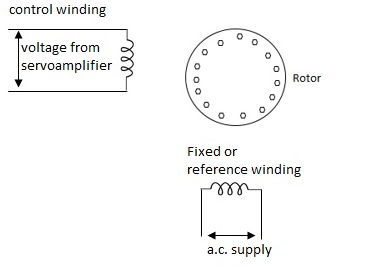
Fig 1. AC Servomotor
The rotor of A.C. Servo motors are of two types,
(a). Squirrel Cage Rotor
(b). Drag cup type rotor
(a). Squirrel cage rotor: They have high resistance as the rotor is having large length and small diameter. The air gap here is kept small.

Fig 2. Squirrel cage rotor
(b). Drag cup type motor: For the drag cup rotor there are two air gaps. For the rotor a cup of non-magnetic conducting material is used. A stationary iron core is placed between the conducting cup to complete the magnetic circuit. The resistance of drag cup type is high and therefore, has high starting torque. Generally aluminium is used for cup.
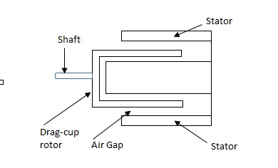
Fig 3. Drag Cup type rotor
Torque-speed characteristic:
The torque speed characteristics of the two phase servomotor depends on ratio of reactance to resistance(X/R).

Fig 4. The torque speed characteristics of the two phase servomotor
(i). For high ‘R’ and low X, the characteristic is linear and
(ii). For high X and low R, it becomes non-linear.
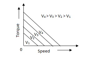
Fig 5. Torque-speed characteristic for various voltage
The torque-speed characteristic for various voltage is almost linear.
(b). D.C. Servomotor:
D.C. Servomotor are separately excited or permanent magnet dc servomotors. The armature of D.C. Servomotors is having large resistance and hence torque-speed characteristic is linear.
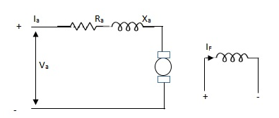
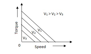
Fig 6. (a) DC Servomotor (b) Torque-speed characteristics
The above graph fig (b), clearly shows that the torque-speed characteristics is a function of control winding voltage as shown below.
T = mw + KVc -- (1)
Where T = Torque developed by motor
w = angular velocity
Vc = control winding voltage
Taking laplace of above equation (1),
T(S) = mS Q(S) + KVc - - (2)
T(S) = JS2Q(S) + FSQ(S) - - (3)
Above equation(3) is the dynamic equation with,
J – moment of inertia
F – coefficient of friction of motor
From equation (2) and (3) the block diagram will be,

Fig 7. Block Diagram of DC Servomotor
Q(S)/Vc = K/Js + F + m - - (4)
Key takeaway
Comparison between A.C. Servomotor & D.C. Servomotor
| A.C. Servomotor | D.C. Servomotor |
|
|
|
1. | They are less efficient | They are more efficient |
2. | They have low power output | They have high power output |
3. | No noise so has smooth operation | These motors have noisy operation |
4. | They do not have any radio frequency noise | These motors have brushes so produce radio frequency noise |
5. | They are maintenance free because of no brushes and slip rings | For these motors, maintenance is required. |
Consider the flow through a short pipe connecting two tanks. The Resistance, R for liquid flow in such a pipe or restriction, is defined as the change in the level difference, necessary to cause a unit change in the flow rate.
R = Change in level difference/Change in flow rate
The Capacitance, C of a tank is defined to the change in quantity of stored liquid necessary to cause in the potential (head).
C = Change in liquid stored/Change in head
A simple liquid level system is shown in the below figure with steady flow rate, Q and steady state head, H.
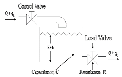
Fig 8. Liquid Level System
Let Q = Steady state flow rate(before any change has occured)
Qi = Small deviation of inflow rate from its steady-state value
Qo = Small deviation of outflow rate from its steady-state value
H = Steady state head (before any change has occurred)
h = Small deviation of head from its steady state value
Let the system be considered linear. The differential equation governing the system is obtained by equating the change in flow rate to the amount stored in the tank. In a small time interval dt, let the change in flow rate be (qi - qo) and the change in height be dh.
Now, Change In storage = Change in flow rate
C dh = (qi - qo) dh

Qo = h/R
On substituting for qo, we get,
 RC dh/dt + h = qi R
The above equation is the differential equation governing the system. The term RC is the time constant of the system .On the Laplace's transform of above equation we get,


The above equation is the required transfer function of the Hydraulic system.
- Collection of components which allows to follow the desired course.
- In a car: ensure that wheels are pointing in the desired direction of motion.
- Convert rotary motion of the steering to the angular turn of the wheel.
- Mechanical advantage is used in this case.
- The joints and the links should be adjusted with precision.
- Smallest error can be dangerous
- Mechanism should not transfer the shocks in the road to the driver's hands.
- It should minimize the wear on the tyres.
RACK AND PINION STEERING SYSTEM
- The pinion moves the rack converting circular motion into linear motion along a different axis
- Rack and pinion give good feedback there by imparts a feel to the driving
- Most commonly used system in automobiles now.
- Disadvantage of developing wear and there by backlash.
RECIRCULATING BALL
- Used in Older automobiles
- The steering wheel rotates the shaft which turns the worm gear.
- Worm gear is fixed to the block and this moves the wheels.
- More mechanical advantage.
- More strength and durable
POWER STEERING
- Too much physical exertion was needed for vehicles
- External power is only used to assist the steering effort.
- Power steering gives feedback of forces acting on the front wheel to give a sense of how wheels are interacting with the road.
- Hydraulic and electric systems were developed.
- Also, hybrid hydraulic-electric systems were developed.
- Even if the power fails, driver can steer only it becomes heavier.
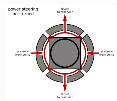
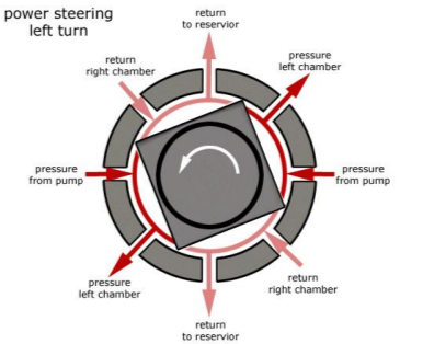
ELECTRIC POWER STEERING
- Uses an electric motor to assist the driving
- Sensors detect the position of the steering column.
- An electronic module controls the effort to be applied depending on the conditions.
- The module can be customised to apply varying amounts of assistance depending on driving conditions.
- The assistance can also be tuned depending on vehicle type, driver preferences
Generally, there are three types of EPS systems: column-type, rack-type and pinion type. The selection of different configurations depends on the package and in-vehicle environment.
The schematic arrangement of a column-type EPS system is shown in figure
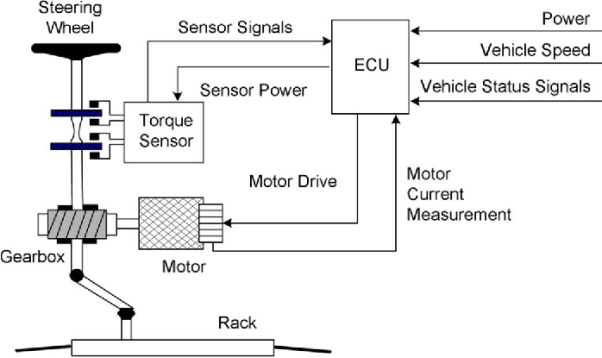
The EPS consists o f a torque sensor, which senses the driver’s movements of the steering wheel as well as the movements of the vehicle; an ECU, which performs calculations on assisting force based on signals from the torque sensor; a motor, which produces turning force according to the output from ECU; and a reduction gear, which increases the turning force from the motor and transfers it to the steering mechanism. The rest of the steering system: Steering Wheel (or hand wheel, HW), Intermediate Shaft (IShaft), and Rack & Pinion are also shown. Basically, the control procedure can be summarized as follows:
1) The torque sensor estimates the torque, which is the command from the human to steer the car, by the torsion bar mechanism inside.
2) ECU calculates the assistant torque based on the command torque (from torque sensor), the vehicle speed (from speed sensor or in-vehicle network) and the status of the electric motor, and then sends the command to the electric motor.
3) The electric motor generates the assistant torque according to the command from the ECU and transfers it to the column through a worm gear mechanism.
4) With the power assistance from the electric motor, the pinion and rack turns the wheels.
STEERING WHEEL DYNAMIC MODEL
The upper part of the system model is the dynamic model o f the human wheel. The MatLab model is as follows:

The differential equation of the steering wheel is:
Th – Ts = Jhw  + Bhw
+ Bhw  + Bhw
+ Bhw  + Khw θhw
Where 7/, and Ts are the torque from driver and torque sensor, respectively. 8hw denotes the angle o f rotation of the steering wheel. Jhw, Bhw and Khw are moment of inertia, damping coefficient and stiffness coefficient. To simplify the model, the stiffness coefficient can be neglected. That is to say, the steering wheel is rigid connection. The dynamic model can be simplified as follows:


THE DYNAMIC MODEL OF PINION AND RACK ASSEMBLY
The pinion and rack are modeled as a mechanic system consists of a mass and a spring. The differential equation of the steering wheel is:
Tr + Tf = Jr  + Br
+ Br  + Kr θ
Where Jr, Br and Kr are the moment of inertia, damping coefficient and stiffness coefficient, respectively. Tr and Tf denote torque from road wheels and steering torque, respectively. 6 represents the road wheel position. The model of the pinion and the rack is as follows
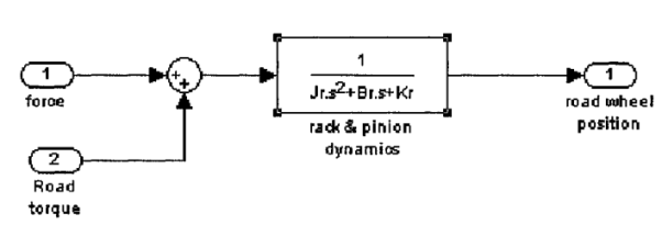
Both of the force torque and the road torque have the same positive direction. Also, to simplify the system, the stiffness coefficient is assumed to be zero. As a result, the model can be simplified as follows

A manipulator is a mechanical system formed by the connection of a set of rigid bodies, links, through joints. Joints provide each pair of connected links with some freedom of relative motion. The description of the spatial location of a rigid body is therefore the basis for the spatial description of a manipulator. The configuration of a rigid body is a description of its position and orientation. The position of a rigid body is determined by a description of the position of an arbitrary point attached to the rigid body. The orientation of a rigid body is determined by the description of its rotations about this point.
Position of a Point
Let us consider a point P of an Euclidean affine space E, where an arbitrary point O has been selected as the origin. The position of P is given by the vector p =  P. With respect to O, the positions of points: P1, P2,..., Pn are described by the vectors: p1 =
  P1, p2 =
  P2,..., pn =
  Pn.
Pn.
For points of the 3-dimensional space, positions are described by vectors p ∈ R3. Let {x, y, z} be an orthonormal basis of R3. The components of a vector p with respect to this basis are identical to the coordinates of P given with respect to the coordinate frame R (O, x, y, z).
Taking the components of the vector p with respect to another orthonormal basis {x’, y’, z’} correspond to a representation of P in a coordinate frame having the same origin, O, and using the unit vectors x’, y’, z’, i.e. R’ (O, x’, y’, z’), as shown in Figure. The relationship between these two representations is given by the base transformation or the coordinate transformation between the two frames of same origin.
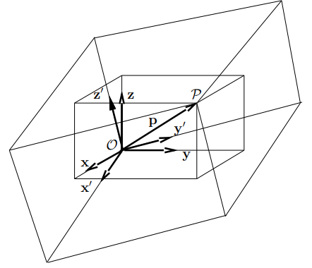
Rotation Transformation
Rotation transformations are transformations that operate on the unit vectors of coordinate frames, while conserving the frame origins. These transformations are equivalent to transformations between orthonormal bases. A rotation transformation is defined by the relationships between the unit vectors of two coordinate frames. The rotation transformation between R (O, x, y, z) and R’ (O, x’, y’, z’), of identical origin O, is described by a 3 × 3 orthonormal rotation matrix S. The columns of S are the components of the three-unit vectors x’, y’, and z’ expressed in the coordinate frame R.
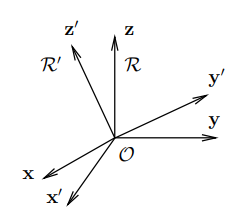
S = (x’(R) y’(R) z’(R))
S-1 = ST
The rows of S define, therefore, the components of the three unit vectors x, y, and z expressed with respect to the coordinate frame R’.
A manipulator is treated as a holonomic system with a structure of an open kinematic chain of n+1 rigid bodies, i.e., links, articulated through n revolute and/or prismatic joints having one degree of freedom.
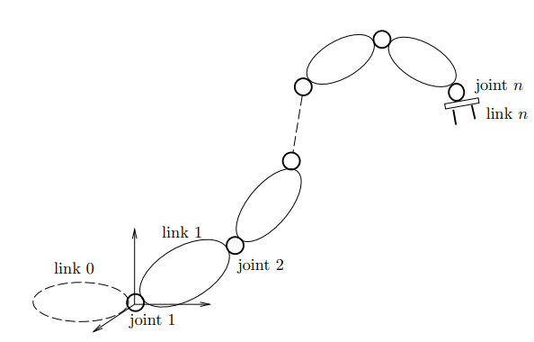
The kinematic relationship between a pair of adjacent links in the chain is described by the coordinate transformation between two coordinate frames attached to the two links. Links are numbered from 0, the base, to n, the end-effector, while joints are numbered from 1 to n
A coordinate frame Ri (Oi, xi, yi, zi) is attached to link i. The position and orientation of the link i with respect to link i−1 is described by the transformation between a coordinate frame Ri−1(Oi−1, xi−1, yi−1, zi−1) attached to the link i − 1 and Ri
Parameters of Denavit-Hartenberg
The kinematic relationship between a pair of adjacent links i − 1 and i connected through a one-degree-of-freedom joint i can be completely determined by a set of four parameters (αi, ai, θi, ρi), called parameters of Denavit-Hartenberg. These parameters define the homogeneous transformation between the two coordinate frames attached to the two links. With the convention shown in Figure, the Denavit-Hartenberg parameters are defined as
αi: the angle between the z-axes of Ri and Ri+1, measured1 about xi;
ai: the length of the common normal to the z−axes of Ri and Ri+1, measured along xi;
θi: the angle between the x-axes of Ri−1 and Ri measured about zi.
ρi: the distance between the x-axes of Ri−1 and Ri measured along zi.

Measuring instruments are used to measure a quantity. When choosing an instrument, the static calibration and static performance of an instrument must be considered
The characteristics of measuring instruments can be classified into the following categories:
1)Static performance characteristics
2)Dynamic performance characteristics
Static calibration refers to the procedure where an input is constant or a variable is applied to an instrument. Instruments are manufactured based on the property of irreversibility or directionality. This implies that change in an input quantity will cause a corresponding change in the output. A calibration standard must be at least ten times more accurate than the instrument to be calibrated.
Static performance characteristics include the linearity performance of the instrument, static sensitivity of the instrument, repeatability of the same results, hysteresis resolution, and the readability of the results.
Static performance characteristics influence data acquisition if the instruments are not properly calibrated prior to the measurement. Understanding quality control and quality assurance procedures for handling equipment is essential for the PE exam.
Linearity
If the relationship between the output and input can be expressed by the equation Q0= P + RQ1, where P and R are constants, then the instrument is considered linear. Linearity is never fully achieved in real-world situations, and the deviations from the ideal are referred to as linearity tolerances. For example, 3% independent linearity means that the output will remain within the values set by two parallel lines spaced ± 3% of the full-scale output from the idealized line. If the input-output relationship is not linear for an instrument, it may still be approximated to a linear form when it is used over a very restrictive range.
Static Sensitivity
Static sensitivity can be defined as the slope of a calibration curve.
Sensitivity = Q0/Q1
Sensitivity influences the input parameters of an instrument. The sensitivity factor can also be referred to as sensitivity drift or scale factor drift.
Repeatability Error
When an instrument is used to measure the same or an identical input many times and at different time intervals, the output is never the same; it deviates from the recorded values. This deviation from the ideal value is referred to as repeatability error.
Hysteresis-Threshold Resolution
When testing an instrument for repeatability, it is often noted that the input-out value does not coincide with the inputs, which are continuously ascending and descending values. This occurs because of hysteresis, which is caused by internal friction, sliding, external friction, and free play mechanisms. Hysteresis can be eliminated by taking readings corresponding to the ascending and descending values of the input and calculating their arithmetic mean.
Professional engineers who work with measurements and instrumentation should understand calibration procedures of various instruments for proper data acquisition.
Machine Tools
Computer Integrated Manufacturing (CIM) encompasses the entire range of product development and manufacturing activities with all the functions being carried out with the help of dedicated software packages. The data required for various functions are passed from one application software to another in a seamless manner.
For example, the product data is created during design. This data has to be transferred from the modeling software to manufacturing software without any loss of data. CIM uses a common database wherever feasible and communication technologies to integrate design, manufacturing and associated business functions that combine the automated segments of a factory or a manufacturing facility. CIM reduces the human component of manufacturing and thereby relieves the process of its slow, expensive and error-prone component.
CIM stands for a holistic and methodological approach to the activities of the manufacturing enterprise in order to achieve vast improvement in its performance. This methodological approach is applied to all activities from the design of the product to customer support in an integrated way, using various methods, means and techniques in order to achieve production improvement, cost reduction, fulfilment of scheduled delivery dates, quality improvement and total flexibility in the manufacturing system.
CIM requires all those associated with a company to involve totally in the process of product development and manufacture. In such a holistic approach, economic, social and human aspects have the same importance as technical aspects. Manufacturing industries strive to reduce the cost of the product continuously to remain competitive in the face of global competition.
In addition, there is the need to improve the quality and performance levels on a continuing basis. Another important requirement ison time delivery. In the context of global outsourcing and long supply chains cutting across several international borders, the task of continuously reducing delivery times is really anarduous task. CIM has several software tools to address the above needs. Manufacturing engineers are required to achieve the following objectives to be competitive in a global context.
• Reduction in inventory
• Lower the cost of the product
• Reduce waste
• Improve quality
• Increase flexibility in manufacturing to achieve immediate and rapid response to:
• Product changes
• Production changes
• Process change
• Equipment changes
• Change of personnel
Basic components of NC system
1.Input medium
2.MCU
3.Machine Tool
Basic Components of an NC System and NC system consists of three basic components:
Program of instructions: The detailed step-by-step commands that direct the actions of the processing equipment. In machine tool applications, the program of instructions is called a part program, and the person who prepares the program is called a part programmer. In these applications, the individual commands refer to positions of a cutting tool relative to the worktable on which the workpart is fixtured. Additional instructions are usually included, such as spindle speed, feed rate, cutting tool selection, and other functions. The program is coded on a suitable medium for submission to the machine control unit. (2) Machine control unit MCU: Consists of a microcomputer and related control hardware that stores the program of instructions and executes it by converting each command into mechanical actions of the processing equipment, one command at a time. The related hardware of the MCU includes components to interface with processing equipment and feedback control elements. The MCU also includes one or more reading devices for entering part programs into memory. The MCU also includes control system software, calculation algorithms, and translation software to convert the NC part program into a usable format for the MCU. Submission to the machine control unit.
(2) Machine control unit MCU: Consists of a microcomputer and related control hardware that stores the program of instructions and executes it by converting each command into mechanical actions of the processing equipment, one command at a time. The related hardware of the MCU includes components to interface with processing equipment and feedback control elements. The MCU also includes one or more reading devices for entering part programs into memory. The MCU also includes control system software, calculation algorithms, and translation software to convert the NC part program into a usable format for the MCU.
Prime movers
The actual meaning of prime mover is a primary source of power. It means all the machinery that provide power for performing different mechanical work. Technically, it is a group of machines that transform energy from thermal, electrical or pressure into mechanical form for use in different sources for some mechanical work. Engines and turbines are examples.
The prime movers are listed based on the sources of energy utilized by them.
A. Thermal prime movers These are the prime movers which use the thermal energy of source to produce power. Different thermal prime movers are given below: -
Fuels (Heat engines): - These prime movers use several fuels like petrol, diesel, oil, gas to produce mechanical power. Heat engines are two types: -
1. External combustion engines: -Reciprocating steam engines Steam turbine Closed cycle gas turbine
2. Internal combustion engines: -Reciprocating I.C. Engines Open cycle gas turbine
- Nuclear (Nuclear power plant): - This prime mover utilises the heat energy of atoms by fission or fusion method to develop the mechanical power. It is chiefly used in nuclear power plants. Different radioactive components like uranium, thorium is used for these fission or fusion process in a nuclear reactor.
- Geothermal: - In this kind of prime mover the heat energy is recovered from a certain depth or the hot part of the earth beneath earth surface then it is transformed into mechanical by the proper engine.
- Biogas: - Biogas is principally produced from garbage or any other waste which is used to generate power by the prime mover in a biogas plant.
- Solar energy: - The solar energy spread to the earth in the form of radiation or electromagnetic waves. This energy trapped in with the help of solar panel made up of semiconductor element. This heat energy is then turned into power.
B. Non-thermal prime movers: - These kinds of prime movers do not use the heat energy to transform it into mechanical power. The following are the non-thermal prime movers:
- Hydraulic turbines: - This kind of prime mover uses the stored potential energy of water to generate power.
- Wind power: - With the help of the wind turbine, wind energy is transformed into power.
- Tidal power: - The energy of tides from the ocean is transformed into power by the use of the turbine which is known as tidal power.
System generators
System Generator is a powerful tool that integrates Xilinx FPGA design process with MATLAB’s Simulink which uses a high-level description to easily realize a complex system. We first design the system and verify its functionality in the Simulink environment. The graphical high-level description of Simulink significantly facilitates modeling, simulating, and analysing the design.
A control system is a set of mechanical or electronic devices which control the other devices. In control system behaviours of the system is desired by differential equations.
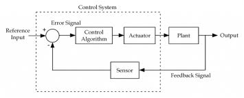
The above figure shows a feedback system with a control system. The components of control system are:
i) The actuator takes the signal transforms it accordingly and causes some action.
Ii) Sensors are used to measure continuous and discrete process variables.
Iii) Controllers are those elements which adjust the actuators in response to the measurement.
Open loop systems:
This is the loop of control system without any feedback. In this the control action is not dependent on the desired output.

Fig. 9 open loop control system
Example of open Loop systems are the traffic signals, Automatic washing machine and in fields control d.c. Motor.
G(s) = c(s)/R(s) -------(1)
Closed loop systems:
This is a type of control system with feedback. In this type of system. The control action is dependent on the desired output.

Fig 10. Closed Loop control system
The error signal is again fed to controller to the error and get desired output.
G(s) – forward amplification
H(s) _ Reverse amplification
Above system is with negative feedback.
Positive feedback is used only in oscillators and other use is not known as discussing only negative feedback.
[ R(s) – c(s) H (S) ] G(s) = c(s)
R (s) G(s) = [1+G(s) H(s)] c(s)
C(s)/R(S) = G(S)/1+G(s) H(s)
So, the transfer function of closed Loop system is
C(s)/ R(S) = G(s)/ 1+G(S) H(S) --------(2)
If numerator of above equation (2) is equalized to zero we get zeros of closed Loop Transfer function [G(S) = 0]
If dominator of equation (2) is equaled to zero we get polls of the closed loop transfer function [ 1+G(s) H(S) = 0]
1+ G(S) H(s) = 0 [ characteristic Equation]
Stability of the system is determined by the location of its poles.
Comparisons between open Loop and Closed Loop system
Open Loop System | Closed Loop system |
1.It does Not have any feedback. | 1. This system comprise of feedback |
2.As no feedback so easier to build. | 2.As it has feedback so difficult to build |
3.Theaccuracy of this system depends on the calibration of input. | 3.They are accuracy because of the feedback. |
4.Open Loop system are more stable. | 4.In closed Loop system stability depends on system components. |
5.optimization is not possible | 5. Optimization is possible |
6.These systems are not reliable. | They are more reliable |
Example 1. For the circuits given below write the voltage equations:
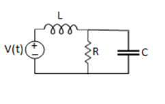
Solution: Let current i1be in loop 1 current and i2 for loop 2
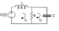


Que. Write the loop equations for the given circuit below?
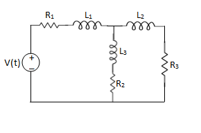
Solution:
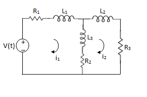
For loop 1

For loop 2

Q) Write the integro-differential equation for the loop currents shown below.
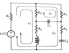
Sol: Equation for loop 1 with current i1
v(t)=(R1+R2+R4)i1 +L -R2 i2+ R5i3
Equation for loop 2 with current i2
-R2i1+(R2+R3) i2 + +R3i3 = 0
Equation for loop 3 with current i3
V(t) = R1i3+R3i3+(R1+R3+R5) i3+
Q) For the given network write the integro differential equation?
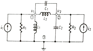
Sol: Let V1 and V2 be the node voltages.
Equation for node v1 will be
 +
+ +
+ +C1
+C1 = i1
= i1
 + C2
+ C2 + C1
+ C1 +
+ = i2
= i2
It is a technique for solving differential equations. The time domain differential equations are transformed into algebraic equation of frequency domain. After solving the algebraic equation in frequency domain, the result then is finally transformed to time domain form to achieve the ultimate solution of the differential equation.
The Laplace Transform is given as
F(s)= dt
dt
The advantages of Laplace Transform are:
1) It is systematic.
2) It gives total solution (transient and sustained solution) in one operation.
3) The initial conditions are automatically specified in the transformed equations.
There are many functions which do not have Laplace Transforms. These functions are not generally used in analysis of linear systems. But some conditions can be defined to get Laplace transformation of such functions. The Dirichlet condition defines the necessary condition for transformation of some functions such as:
a) The function should be continuous. The function should be single-valued.
b) The function must be of exponential order.
Properties of Laplace Transform:
1) Linearity Property:
If f1(t) and f2(t) are two functions of time. Then, in domain of convergence
L[a f1(t)+b f2(t)]=a + b
+ b
=aF1(s)+bF2(s)
2) Differentiation Property:
If x(t) is function of time then Laplace transform of nth derivative is given as


3) Integration Property:
The Laplace of nth order integral is given as
L[ ]=
]= +
+
L[f-n(t)]= +
+ +
+ +……….
+……….
As  ……..=0. Hence
L[f-n(t)]=
Laplace Transform of Basic R, L and C components
LAPALACE TRANSFORM:
If LT[f(t)]= F(s)
Where F(s)= dt
dt
f(t) F(s)
F(s)
 sF(s)-f(0-)
 f(t)
f(t) S2F(s)-sf(0-)-f’(0-)
Now, we find Laplace for 
 =
= +
+
Now if f(t)=ic(t) [current through capacitor]
 =
= +
+
 =
= +
+
=[q(0)-q( )]+
)]+
=[q(0)-0]+
Multiplying both sides by 1/C
 =
= +
+
Vc(t)= +
+
Vc(t)=Vc(0)+
By Laplace Transform
Vc(s)= +
+
Vc(s)= +
+

Fig 11. Laplace transformed circuit for C
Now by source conversion
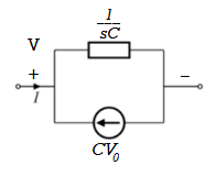
Fig 12 .Source transformed circuit for C
 =
= +
+
Now if f(t)=VL(t) [voltage across inductor]
 =
= +
+
 =
= +
+
= -
- ]+
]+
= -0]+
-0]+
Multiplying both sides by 1/L
 =
= +
+
iL(t)=iL(0)+
By Laplace Transform
IL(s)= +
+
IL(s)= +
+
NOTE: Voltage------->Series circuit
Current------->Parallel circuit
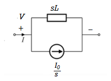
Fig 13. Laplace transformed circuit for L
By source transformation

Fig 14. Source transformed circuit for L
Current through capacitor
iC(t)=
IC(s)=C[sVc(s)-Vc(0)]
Vc(s)= +
+
Voltage about inductor,
VL(t)=
VL(s)=L[sIL(s)-iL(0)]
IL(s)= +
+
It is the ratio of Laplace transform of the output to Laplace transform of input with all initial conditions zero.

Fig 15. System with Transfer Function G(s)
Poles and zero of a Transfer Function:
The transfer function can be represented by the ratio of two polynomials
G (S) = a0sn+a1 sn-1-------+an/b0sm+b1sm-1+-----+bn
a0—an ---- constants
G(S) = K(s+z1) (s+z2) (as2+bs+c)/(S+A) (s+p2) (As2+Bs +c)
K= a0/b0 ( Gain of system)
For poles –They are the values of s for which
G(S)
(S+p1)(S+p2)(AS2 + BS + C) = 0
S= p1, -p2 , -B±B2-4Ac/2A
For ZEROS – They are the values of s for which
G(S)0
S=-z1, -z2 , -b±b2-4ac/2a
- Location of poles and zeros in s place determines the reliability of the system
- There can be multiple poles and zeros
- The numerator of transfer function when equalized to zero gives zero of system
- The denominator of transfer function which equalized to zero gives poles of system.
Key takeaways
- The numerator of transfer function when equalized to zero gives zero of system.
- The denominator of transfer function which equalized to zero gives poles of system.
Mechanical System
(a) Translational system
(b) Rotational system
(a) Translational system
The motion that takes place along a straight line is called translational motion. The forces that resist motion are -
Inertia: A body with mass ‘N’ acceleration ‘a’ will produce inertia fm(t)= malt N’ acceleration ‘a’ will produce inertia
fm(t)= M a(t)
In terms of velocity
Fm(t) = M dv(t)/dt
In terms of displacement
Fm(t)= Md2/dt2µt
Damping force: The damping force is proportional to velocity for vis case function
F0(t) = B(t) = B dx(t) /dt
B Damping coefficient N/M sec
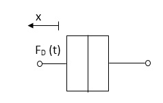
Fig 16. Damping force
Spring force: A spring stores potential energy. The releasing force of a string is proportional to the displacement.
Fk(t)  x(t)
x(t)
Fk(t) = k x (t)
Fk(t) = k 
K = string constant N/m.

Fig 17. Spring force
Fk(t) = k 
K = string constant N/m.
(b) Rotational system:
The motion of a body about a fixed axis is called as Rotational motion. The types of torques which can resist the motion are
Inertial Torque: The inertial torque is the product of moment of inertia I and angular acceleration.
TI(t) = J (t)
(t)
TI(t) = Jd/dt w(t)
TI(t) = Jd2ø(t)/dt2(N-m)
W (t) – Angular velocity
Ø(t) = Angular displacement
Damping Torque: It is product of damping efficient B and angular velocity w
T0 (t) = B w(t)
T0(t) = B d/dt ø(t)
Spring Torque: It is the product of torsional stiffness and angular displacement
Tø(t) = k ø(t)
K = N.m/rad
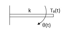
Fig 18. Spring Torque
D’Alembert’s Principle
For anybody, the algebraic sum of externally applied forces and the forces resisting motion in any given direction is zero.
Ex.
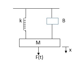
In above figure applying D’Alemberts principle to write the equation of motion
As force f(t) acts downwards all other forces (of k,B,x) acts Opposite to it to considering f(t) as the and all other forces negative.
F(t)+fm (t) + fD(t) +fx(t) =0
f(t)- M d2x(t)/dt2+B dx(t)/dt +x(t)
Example
Q.1 Draw the free body diagram and write the differential equation for system below.
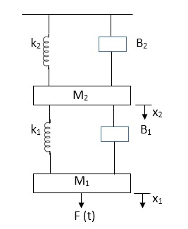
Fig 19. Mechanical system
Sol: The free body diagram for M1 will be
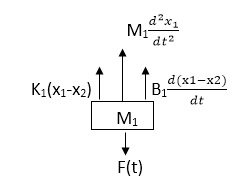
Fig 20. FBD
F(t) = M1 d2/dt2x1+ B1 d/dt (x1-x2)+ k1(x1-x2)
Similarly for M2we have

Fig 21. FBD
K1(x1-x2) + B1d/dt(x1-x2) = k2x2+M2d2/dt2+B2dx2/dt
Electrical System
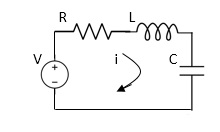
Fig 22. RLC Circuit
Example-1 For circuit shown above find value of current I?
Applying Kirchoff’s voltage Law
V= Ri +Ldi/dt +1/c
V= Rdq/dt + L d2q/dt2+q/c
Now By kirchoff’s current low
I= V/R+ 1/L  + cdv/dt
But V= dø/dt
I= 1/R dø/dt + 1/L ø+cd2ø/dt2
But v= dø/dt
I= 1/R dø/dt+ 1/L. ø+c d2ø/dt2
Example-2 For the given mechanical system below draw the analogus system (force. Voltage )& find V0(s)/V1(s)
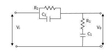
Soln.
Let Z1 = R2 11 1/c2
=R2*1/c2s/R2+1/c2s
Z1= R2/1+R2c2s
Let Z2 = R1+1/c1s
Z2= 1+R1c1s/c1s
V0(s)/vi(s) = z2/z1+z2
=1+R1c1s/c1s/R2/1+R2c2s+1+R1c1s/c1s
V0(s)/v0(s) =(c1+R1c1s) (1+R2c2s)/R2c1s+1+sR1c1s2R1R2c1c2
Electronic system and Electro-mechanical system.
Stepper Motors
It is a device whose output is completely controlled by the input pulses. There are two types of stepper motors:
a) Variable Reluctance
b) Permanent Magnet
A variable reluctance stepper motor consists of stator having a common frame and rotate n a common shaft. Rotor and stator have toothed structure and teeth are of same size so that it can be aligned on same axis. The stator re pulse excited while the rotor is unexcited. When stator is excited stator and rotor teeth are aligned to minimum reluctance position. The stator torque of the rotor depends on the displacement  .
.
There are two positions of zero torque:
i) For  =0 when rotor and stator are aligned is called stable position because slight disturbance from this position in either direction brings the rotor back to its original position.
Ii) For  = 180/T when tooth and stator are aligned is called unstable position. This is because of slight disturbance from this position in either direction makes the rotor move away from it.
For multiple stack stepper motor, Step angle  = 360/nxT
n: number of stacks
T: number of rotor teeth
These motors are used in computer peripherals.
Tacho Generators
These are electromechanical devices which convert mechanical input at their shaft to corresponding electrical output. It is basically used to measure speed of motor. It has negative feedback. These devices are most commonly used to find speed of any rotating machine.
| D.C. Tachometer | A.C. Tachometer |
1. | They convert rotational speed into a proportional dc voltage. | They convert the rotational speed into a proportional ac voltage. |
2. | It uses a permanent magnet for producing magnetic field. It contains iron core rotor. | It works on principle of induction generator. |
3. | The permanent magnet controls the magnetic field therefore the induce voltage at terminal of armature is proportional to shaft speed. | The reference winding is supplied by reference voltage and the output voltage is induced across the output winding. |
4. | The polarity depends on direction of rotation. | The amplitude and phase depends on the direction of rotation. |
Synchros
Its construction is similar to a three-phase alternator. The stator is made of laminated silicon steel and rotor is dumbbell shaped magnet with a single winding.
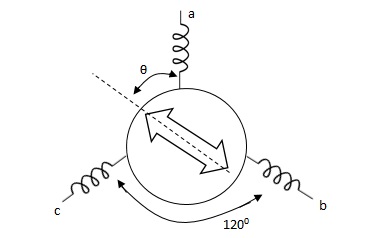
Let the applied a.c. Voltage to the rotor is,
er = ErSinwot
Let the rotor be at angle of ϴ, then voltage in each stator coil with respect to neutral,
Ean = KErSinwot cos(ϴ)
Ebn = KErSinwotcos(ϴ + 1200)
Ecn = KErSinwotcos(ϴ + 2400)
Magnitude of stator terminal voltage,
Ecb = Ecn – Ebn
= KErSinwot[cos(ϴ + 2400) – cos(ϴ + 1200)]
= KErSinwot(√3 Sinϴ)
Ecb = √3KErSinwot Sinϴ
Similarly,
Eac = √3KErSinwot Sin(ϴ + 1200)
Eba = √3KErSinwot Sin(ϴ + 2400)
When ϴ = 0, Ecb, Ean = 0
Hence, input to the synchro transmitter is the angular position of motor shaft and output are three phase voltage which are function of shaft position.
Synchro Transformer
Its basic working principle is similar to the synchro transformer. Here the rotor is cylindrical type. It is an electromechanical device. The combination of synchro transmitter and synchro transformer is used as an error detector.
The basic diagram is shown below

Let transmitter rotate at an angle ϴ and control transformer rotor rotate in same direction through α. Then,
φ = ( 90 - ϴ + α )
Voltage across rotor terminal is given as,
e(t) = K1Vrcos ϴSinwot
e(t) = K1VrSin(ϴ - α) Sin wot
From above equation we can conclude that when two rotor shafts are not aligned, the rotor voltage of transformer is a sine function of difference between two angles.
For small angular displacement between two rotor position,
e(t) = K1Vr(ϴ - α)Sinwot
Analogy Between Electrical and Mechanical System:
Force -voltage | Force -current | Mechanical Translatory | Mechanical Rotational |
1.Voltage (v) | Current | Force (f) | Torque (T) |
2.Charge(q) | Flux (ø) | Displacement(x) | Angular Displacement(ø) |
3.current. | Voltage | Velocity v(t) | Angular velocity(w) |
4.Inductance(l) | Capacitance(c) | Mass (m) | Moment of inertia (J) |
5. Resistance(R) | Conductance G= (1/R) | Damping coefficient (B) | Damping Coefficient (B) |
6.Reciprocal of capacitance(1/c) | Inverse of Inductance (1/L) | Stiffness (K) | Stiffness(K) |
Generally, a function can be represented to its polynomial form. For example,
F(s) = f0sn + f1sn -1 +f2sn – 2 + f3sn – 3 + . . . + fn – 1s1 + fn
Now similarly transfer function of a control system can also be represented as


Where K is known as the gain factor of the transfer function.
Now in the above function if s = z1, or s = z2, or s = z3,….s = zn, the value of transfer function becomes zero. These z1, z2, z3,….zn, are roots of the numerator polynomial. As for these roots the numerator polynomial, the transfer function becomes zero, these roots are called zeros of the transfer function.
Now, if s = p1, or s = p2, or s = p3,….s = pm, the value of transfer function becomes infinite. Thus, the roots of denominator are called the poles of the function.
The transfer function of system is ratio of output to the input.
References:
1. Automatic Control Systems, Benjamin. C. Kuo, Prentice Hall of India, 7th Edition,1995.
2. Digital Control and State Variable Methods, M. Gopal, 2nd Edition, TMH, 2007.
3. Feedback and Control Systems, Stubberud, Schaum’s Outline Series, TataMcGraw-Hill, 2007.
4. Linear Control System Analysis and Design, John J. D’azzo & Constantine H.Houpis, Tata McGrow-Hill, Inc., 1995.
5. Modern Control Systems, Richard C. Dorf & Robert H. Bishop, Addison –Wesley, 1999.