Unit - 2
Dynamic force analysis of planar linkages
Dynamic force analysis of planar linkages such as four bar chain
In this phase we will anticipate that the movement of the device elements are certain beforehand, e.g. The location pace and acceleration of every inflexible frame is thought or may be calculated with the aid of using appearing kinematic analysis.
We shall additionally anticipate that the mass and the instant of inertia of every device member is thought or may be calculated from the given data. There can be outside forces of acknowledged significance and path or friction forces present.
However, we will anticipate that there's one outside force (which include the enter torque) of an unknown significance however of a acknowledged path and a factor of application. The device is in a country of dynamic equilibrium beneathneath the motion of those forces.
We would love to decide the joint forces, forces appearing at the participants and the significance of the unknown outside force. The above trouble is typically called kinetostatics or Wittenbauer's 2d trouble. Such a method is legitimate beneathneath regular country situations and while the mechanism concerned is a confined mechanism.
The enter speed(s) need to be nearly consistent for those assumptions to be legitimate or the adjustments withinside the pace and acceleration of the enter hyperlink is decided with the aid of using a few different means.
In kinetostatics we decide the speed and acceleration of every device member with the aid of using appearing kinematic analysis.
If the mass and mass distribution of the participants are acknowledged, we are able to calculate the inertia forces and torques. Next we practice D'Alambert's precept in order that we are able to deal with the fictional inertia forces as though they may be outside forces.
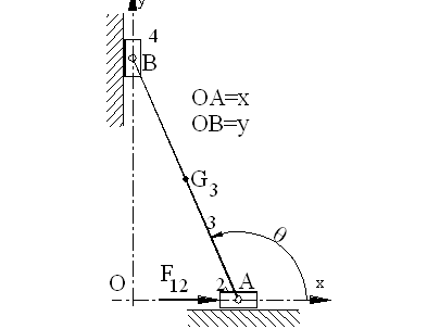
Graphical Method
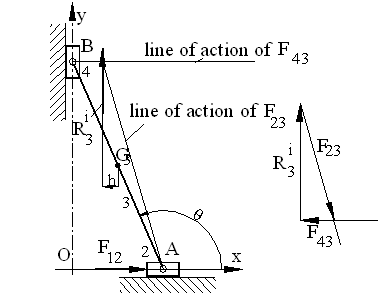
Link 4 is a two force, link 3 and link 2 are three force members. For link 3, since R3i is known, we determine the point of concurrency of the three forces and draw the force polygon for the equilibrium equation R3i +F23+F43=0 as shown in Fig.
For link 4, G14=-F34=F43.
For link 2,
F32+F12+G12=0.
Since F32 = -F23,
The force polygon for the equilibrium equation is that drawn for link 3 with all the arrows reversed. Hence G12= - R3i and F12= -F43.
Mechanisms are designed to perform positive preferred work, via way of means of generating the special movement of positive output member. Lt is commonly required to discover the pressure or torque to be carried out on an enter member, while one or greater forces act on positive output member(s).
Calculation of enter pressure or torque over the whole cycle could be had to decide the electricity requirement.
When the loads and moments of inertia of the contributors are negligible, static pressure evaluation can be achieved.
Otherwise, mainly at excessive speeds, considerable forces or torques could be required to supply linear or angular accelerations of the diverse contributors.
The equal will ought to be taken into consideration in the evaluation. Lt is likewise required to discover the forces on the joints for correct design.
In the case of dynamic systems, linear acceleration of every link (CC) and the angular accelerations of the contributors are evaluated. The corresponding forces and moments are calculated (made from acceleration and inertia).
D'Alembert's precept is a technique of making use of fictitious forces / torques referred to as inertia pressure / torque, same and contrary to the pressure or torque required to supply acceleration in every member, so that it will produce a static circumstance that's referred to as dynamic equilibrium.
Then the device may be dealt with as static, which allows utility of strategies of static pressure evaluation.
Dynamic pressure evaluation is the assessment of enter forces or torques and joint forces considering movement of contributors. Evaluation of the inertia pressure /torque are explained first. Methods of static pressure evaluation are explained.
Reciprocating mechanism by graphical method, virtual work method
The idea of mechanical paintings is essential to the have a look at of mechanics. The mechanical paintings performed via way of means of a pressure is described because the scalar made of that pressure via way of means of the displacement via which it acts: paintings is a scalar quantity, in comparison with forces and displacements, which can be vector portions characterised via way of means of magnitudes and directions.
Consequently, paintings portions are less complicated to govern than forces and displacements, and this simplification makes paintings primarily based totally formulations of mechanics very attractive.
Newtonian mechanics is primarily based totally at the ideas of forces and moments, which can be vector portions. The equilibrium situations said via way of means of Newton's regulation are expressed of their maximum well-known shape as vector equations, and vector algebra is needed for maximum realistic packages. While it's far commonplace to make a difference among externally carried out loads, inner forces and response forces, Newton's circumstance for equilibrium states that the sum of all forces ought to vanish,without making any difference among them.
The answer manner entails the dedication of all forces, along with inner and response forces. Newton's method efficiently determines forces and displacements, however it will become an increasing number of hard and tedious for issues of growing complexity.
It has huge variety of packages like pumps, engines, and compressors. Generally, the mechanism includes inflexible hyperlinks and a piston which can be related via way of means of frictionless joints and restrained to transport in a unmarried plane. The hyperlink AC is referred to as a "crank-shaft" and the hyperlink CB is referred to as a "connecting rod".
The slider-crank mechanism has best one diploma of freedom for the reason that area of each hyperlinks may be targeted via way of means of the unmarried impartial coordinate θ In this case, the crank-shaft, AC, weighs 20 N and connecting rod, CB, weighs 35 N.
The weight of the hyperlinks pushes the piston closer to right. To hold this machine in equilibrium, a pressure, F, of 70 N pushes withinside the contrary direction. Determine attitude θ for the equilibrium of the slider-crank mechanism.
In a reciprocating engine, let OC be the crank and PC, the connecting rod whose centre of gravity lies at G. The inertia forces in a reciprocating engine may be obtained graphically as discussed below:
1. First of all, draw the acceleration diagram OCQN by Klien’s construction. We know that the acceleration of the piston P with respect to O,
APO = aP = 2 NO,
Acting in the direction from N to O. Therefore, the inertia force FI of the reciprocating parts will act in the opposite direction as shown in Fig.
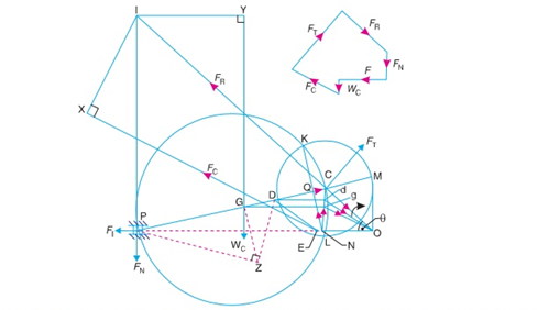
Fig. Inertia forces is reciprocating engine, considering the weight of connecting rod.
2. Replace the connecting rod by dynamically equivalent system of two masses as discussed in Art. 15.12. Let one of the masses be arbitrarily placed at P. To obtain the position of the other mass, draw GZ perpendicular to CP such that GZ = k, the radius of gyration of the connecting rod. Join PZ and from Z draw perpendicular to DZ which intersects CP at D. Now, D is the position of the second mass.
Note: The position of the second mass may also be obtained from the equation,
GP × GD = k2
3. Locate the points G and D on NC which is the acceleration image of the connecting rod. This is done by drawing parallel lines from G and D to the line of stroke PO. Let these parallel lines intersect NC at g and d respectively. Join gO and dO. Therefore, acceleration of G with respect to O, in the direction from g to O,
AGO = aG = ω2 × gO
And acceleration of D with respect to O, in the direction from d to O,
ADO = aD = ω2 × dO
From D, draw DE parallel to dO which intersects the line of stroke PO at E. Since the accelerating forces on the masses at P and D intersect at E, therefore their resultant must also pass through E. But their resultant is equal to the accelerang force on the rod, so that the line of action of the accelerating force on the rod, is given by a line drawn through E and parallel to gO, in the direc- tion from g to O. The inertia force of the connecting rod FC therefore acts through E and in the opposite direction as shown in Fig. 15.22. The inertia force of the connecting rod is given by
FC = mC 2 gO
Where mC = Mass of the connecting rod. …….(i)
A little consideration will show that the forces acting on the connecting rod are :
(a) Inertia force of the reciprocating parts (FI ) acting along the line of stroke PO,
(b) The side thrust between the crosshead and the guide bars (FN) acting at P and
Right angles to line of stroke PO,
(c) The weight of the connecting rod
(W C = mC.g), (d) Inertia force of the connecting rod (FC),
(e) The radial force (FR) acting through O and parallel to the crank OC, (f) The force (FT) acting perpen- dicular to the crank OC.
Now, produce the lines of action of FR and FN to intersect at a point I, known as instantaneous centre. From I draw I X and I Y , perpendicular to the lines of action of FC and W C. Taking moments about I, we have
FT × IC = FI × IP + FC × I X + W C × I Y ...(ii)
The value of FT may be obtained from this equation and from the force polygon as shown in Fig, the forces FN and FR may be calculated. We know that, torque exerted on the crankshaft to overcome the inertia of the moving parts = FT × OC
Key Takeaways:
Consequently, paintings portions are less complicated to govern than forces and displacements, and this simplification makes paintings primarily based totally formulations of mechanics very attractive.
Cam dynamics
In this newsletter we’ll have a take a observe the effect of the rotation of the cam at the dynamics of the valve educate. For maximum avenue riders information the cam dynamics is of basically educational hobby as a Velo OHV valve educate is nicely designed and it's far not likely they'll revel in any problems. However, for the ones proprietors who race or need to apply the entire overall performance in their engine
Valve breakages (because of excessive effect loads) or the valve making touch with every different and / or the A cam rotates at 1/2 of engine velocity and in doing so the cam generates a rotational speed relative to the followers. More importantly the because the cam follower starts to be lifted through the cam, it produces elevate which produces a boost speed. If we ought to layout an excellent cam (which we are able to’t), it might have a steady speed profile, which might produce no acceleration. It’s this acceleration, which produces the pressure that both reasons the valve educate to lose touch with the cam (valve float) or create damaging forces at the valve educate (cam, followers, pushrods, pinnacle rockers, valve springs and valve).
Modern engine designers move even in addition to have a take a observe the fee of extrade of acceleration, that's referred to as Jerk and the fee of extrade of Jerk but for our interests, we’ll best have a take a observe elevate, speed and acceleration. Similarly, cam designers over time have used distinct equations to generate elevate curves such has harmonic, sinusoidal, polynomial to acquire their preferred cam dynamics. Again, that is past the hobby of maximum of us. To examine valve dynamics engine designers use effective laptop programmes, which calculate the elevate, speed and acceleration each diploma of rotation or less.
Even whilst calculations are made at each diploma of rotation, the minor versions in measurements produces ‘noise’, which expert programmes ‘smooth’ through making use of what are basically a chain of averaging calculations. So let’s begin searching on the dynamics, which basically for consistency and simplicity of assessment I even have best proven for the inlet lobe of the cam. Looking on the acceleration graphs that comply with you'll note that acceleration and consequently the ensuing pressure has each a superb and bad aspect. The superb aspect all through the primary a part of the elevate curve exerts a pressure thru the cam follower at the cam. At the factor it passes via the 0 axes, this pressure modifications to a bad pressure i.e. the valve tools with out spring strain might try and free touch with the cam.
You will don't forget from the remaining article that the M17/2 had an nearly equal elevate profile to the M17/3, apart from the later cam having quietening ramps. The following elevate, speed and acceleration diagrams indicates the impact of the ramp.
The speed diagram virtually indicates the impact of the ramp withinside the early a part of the elevate curve, however the basic speed curve and most speed is similar. Next we'lll have a take a observe the impact growing the reside of the cam, however maintaining the elevate up and raise down profile similar. For this we can examine a M17/eight cam collectively with a changed M17/eight which has been reprofiled to growth the duration.
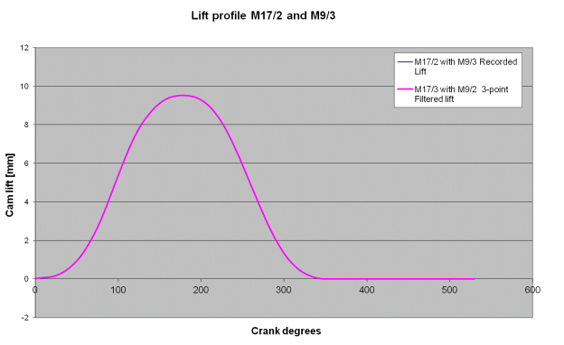
As you will count on the rate and acceleration curves are similar, but we are able to virtually see that the cam has been changed through growing the reside of the cam barely at the best elevate factor, which produces a drop in acceleration at approximately the 260 diploma mark.
This is specifically noticeable at the bad part of the acceleration curve wherein the valve tools is controlled through valve springs. What also can be visible from the elevate, speed and acceleration curves is the effect of the massive reside duration at approximately 260 tiers which reduces the acceleration to 0. Obviously in case you are the usage of this cam for racing it might gain from lightened valve tools and a fixed of valve springs whose pressure characteristics higher fit the acceleration profile of the cam.
Camshaft:
A camshaft is a shaft to which a cam is mounted or of which a cam bureaucracy an imperative part. The camshaft changed into defined in 1206 via way of means of Turkish engineer Al-Jazari. He hired it as a part of his automata, water-elevating machines and water clocks along with the fortress clock. Among the primary vehicles to make use of engines with unmarried overhead camshafts have been the Maud slay designed via way of means of Alexander Craig and brought in 1902and the Marr Auto Car designed via way of means of Michigan local Walter Lorenzo Marr in 1903.
Uses of Camshaft:
The camshaft is used to perform poppet valves in inner combustion engines with pistons. It includes a cylindrical rod walking the period of the cylinder financial institution with some of rectangular lobes sticking out from it, one for every valve. The cam lobes pressure the valves open via way of means of urgent at the valve, or on a few intermediate mechanism, as they rotate.
Purpose:
A camshaft acts as a timing tool that controls the hole and ultimate of the consumption and exhaust valves, in addition to putting the valve overlap that happens on the pinnacle lifeless centre at the exhaust stroke. The shaft is built with numerous journals that trip on bearings in the engine.
It has egg-fashioned lobes that actuate the valve teach, both via way of means of transferring lifters and pushrods or via way of means of pushing immediately at the valve stems.
The camshaft is sure to crankshaft rotation via way of means of a timing chain, timing belt or timing gears, and disasters withinside the camshaft force can permit the valves to touch the piston crowns, inflicting large inner damage.
Additional Functions of a Camshaft:
In older engines camshafts can also have gears machined into them that perform the distributor and the oil pump.
Engines with a desmodromic valve teach use as a minimum cams, as there may be a push-open cam and a pull-near cam, as opposed to the conventional push-open cam with valve springs to tug the valve close because the cam rotates beyond the lobe and lower back onto the bottom circle.
The courting among the rotation of the camshaft and the rotation of the crankshaft is of important importance.
Since the valves manipulate the go with the drift of the air/gasoline combination consumption and exhaust gases, they have to be opened and closed at the proper time for the duration of the stroke of the piston.
Jump-off phenomenon
We recognize thoroughly that a (reciprocating)cam and follower is usually used to reap reciprocating movement in vertical route in any gadget. Eg.(IC Engine Valve Operation) The Jump phenomenon happens in case of cam running beneathneath the motion of compression spring load. This is brief conditions that arise best with excessive pace, fairly bendy cam-follower structures.
With leap the cam and the follower separate owing to excessively unbalanced forces exceeding the spring pressure all through the duration of terrible acceleration.
This is unwanted for the reason that the essential characteristic of the cam-follower gadget; the constraint and manipulate of follower movement aren't maintained. Also associated are the quick lifestyles of the cam flank surface, excessive noise, vibrations and negative motion.
Jump and Crossover Shock: A cam-follower retained towards the cam with a compression keeping spring will beneathneath positive conditions, leap or jump out of touch with the cam. This circumstance is maximum possibly to arise with low values of damping and with excessive pace cams or pretty bendy follower trains. Crossover surprise happens in a nice power cam mechanism while touch movements from one facet of the cam to the other.
Clearance and backlash are taken up all through the crossover, and effect happens. Crossover takes region at the upward push or go back movement while the acceleration adjustments signal and while the speed is at its height.
The consequences may be decreased with the aid of using preloading the gadget to get rid of backlash, with the aid of using designing for an extremely low height velocity, and with the aid of using inflexible follower train.
Roth artwork states that leap will now no longer arise in excessive pace structures if as a minimum complete cycles of vibration arise all through the nice acceleration time-c program language period of the movement. If a smaller wide variety of cycles exist all through this era then, he states, the gadget must be investigated mathematically to decide if leap exists.
In maximum of the cams together with disc cams, plate cams, the cam is chargeable for upward motion of the follower. But curiously the cam isn't chargeable for the downward motion (go back) of the follower. Instead of cam, acceleration because of gravity “g” is chargeable for the downward movement. As we recognize, “g” is restricted with the aid of using 9.eighty one m/s2.
Here comes the trouble, if the rotational pace of the cam may be very excessive, it ends in boost up the follower at a completely excessive rate. No trouble approximately the upward acceleration of the follower, the cam will take care. We cannot count on the cam to transport downward in an acceleration extra than “g”. It makes the follower to lose touch with the cam.

This is known as leap phenomenon.
Cam and follower mechanism is a favored mechanism because of its vital features of all maximum all of the reciprocating machines utilized in transportation, medical, and manufacturing and so on industries.
A cam is a rotating or translating a part of the cam follower mechanism that can transmit from one kind movement to another. Actually, cam follower mechanism may be used to transmit every day to abnormal movement at a totally low fee this is very difficult even at better expenses through the use of different to be had sophisticated means.
Mahesh R. Mali et al. Recommended quite a few range of cam and follower linkages that a clothier or researcher can pick primarily based totally on one’s requirements. Cam and follower mechanisms also are used to boom the I.C. Engine performance through diverse optimization techniques. R.L. Norton and R.G. Mosier proposed a layout for the dynamic behavior of cam and follower gadget and its amazing importance in operating of I.C.Engine. J. W. David eta.l recommended an most useful and cost-effective s layout of a cam follower mechanism.
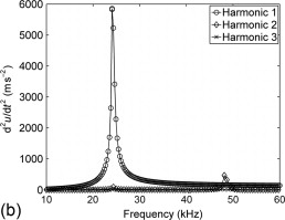
The creator examined this proposed cost-effective layout with the assist of laptop simulation and validated with the statistics already to be had withinside the literature. T. D. Choi et al. Proposed cam follower mechanisms to attain most useful equipment teach answer having lobes profile to be used in car industries. A. Cardona et al. Recommended a cam designing method for a equipment teach to be driven with the assist of motor.
The synthesis and evaluation of a cam follower mechanism is a critical step to attain it economically. N.S.Patel investigated the most useful layout answer for the layout of a cam and follower gadget. At leaping velocity, each follower and cam does not obey every different.
Jumping isn't always ideal in any case due to the fact the confined movement policies are violated along with immoderate noise, vibrations and dangerous operating conditions. We found that spring stiffness as well as compression of the spring is the important thing parameters in the cam and follower mechanisms layout.
Therefore, soar is unwanted in cam and follower mechanisms. So, we need to usually offer enough spring pressure and preload to the cam and follower pair at all of the length to make certain that each cam and follower continue to be in contact in the course of the whole rotation.
This paintings may be prolonged in destiny as much as vibration dimension at the side of the soar velocity.
The most velocity of the cam or soar velocity at the side of frequency of vibration need to be notified to the clothier with inside the preliminary degree of cam and follower mechanism layout.
Key Takeaways:
Clearance and backlash are taken up all through the crossover, and effect happens. Crossover takes region at the upward push or go back movement while the acceleration adjustments signal and while the speed is at its height.
References:
1. Theory of Mechanisms and Machines, Ghosh A. And Mallick A.K., Affiliated EastWest Press Pvt. Ltd., New Delhi, 1988.
2. Theory of Machines and Mechanisms, Shigley J.E. And UickerJ.J.,McGraw-Hill, Inc., 1995.
3. Mechanism and Machine Theory, Rao J.S. And Dukkipati R.V., Wiley-Eastern Limited, New Delhi, 1992.
4. Mechanics of Machines, John Hannah and Stephens R.C., Viva Books.
5. Theory of Machines, Sadhu Singh, Pearson Education.