Unit - 5
Derivation of equation of motion for vibratory system
First, we can provide an explanation for what is supposed via way of means of the identify of this section.
Recall that a gadget is conservative if power is conserved, i.e. ability power + kinetic power = steady at some point of movement.
Free vibration method that no time various outside forces act at the gadget.
A gadget has one diploma of freedom if its movement may be absolutely defined via way of means of a unmarried scalar variable. We’ll speak this in a piece greater element later.
A gadget is stated to be linear if its equation of movement is linear. We will see what this indicates shortly.
We will observe trendy method, and use a spring-mass gadget as our consultant example.
Note that each one vibrations troubles have comparable equations of movement.
Consequently, we will simply clear up the equation once, report the answer, and use it to clear up any vibration trouble we is probably fascinated in. The method to clear up any vibration trouble is:
1. Derive the equation of movement, the use of Newton’s laws.
2. Do a few algebra to set up the equation of movement right into a trendy shape
3. Look up the answer to this trendy shape in a desk of answers to vibration troubles. We have supplied a desk of trendy answers as a separate record that you could down load and print for destiny reference.
We will illustrate the method the use of many examples.
The herbal frequencies are arguably the unmarried maximum vital assets of any mechanical gadget. This is due to the fact, as we will see, the herbal frequencies coincide (almost) with the gadget’s resonant frequencies.
That is to say, in case you follow a time various pressure to the gadget, and pick the frequency of the pressure to be identical to one of the herbal frequencies, you may take a look at very big amplitude vibrations.
When designing a shape or component, you normally need to manipulate its herbal vibration frequencies very carefully.
For example, if you want to forestall a gadget from vibrating, you want to ensure that each one its herbal frequencies are an awful lot extra than the predicted frequency of any forces which are probable to behave at the shape.
If you're designing a vibration isolation platform, you normally need to make its herbal frequency an awful lot decrease than the vibration frequency of the ground that it'll stand on.
Design codes generally specify allowable degrees for herbal frequencies of systems and components.
Once a prototype has been built, it's miles regular to degree the herbal frequencies and mode shapes for a gadget. This is executed via way of means of attaching some of accelerometers to the gadget, after which hitting it with a hammer (this is mostly a normal rubber tipped hammer, which is probably instrumented to degree the impulse exerted via way of means of the hammer at some point of the impact).
By trial and error, you possibly can discover a spot to hit the tool on the way to excite every mode of vibration impartial of any other. You can inform if you have discovered any such spot, due to the fact the complete gadget vibrates harmonically. The herbal frequency and mode form of every vibration mode is then decided from the accelerometer readings.
Impulse hammer exams may even be used on huge systems like bridges or buildings however you want a huge hammer. In a current take a look at on a brand new cable stayed bridge in France, the bridge turned into excited via way of means of first attaching a barge to the middle span with an excessive energy cable; then the cable turned into tightened to elevate the barge component manner out of the water; then, finally, the cable turned into launched hastily to set the bridge
Finally, we resolve the maximum essential vibration issues of all. In engineering practice, we're nearly perpetually interested by predicting the reaction of a shape or mechanical machine to outside forcing.
For instance, we might also additionally want to expect the reaction of a bridge or tall constructing to wind loading, earthquakes, or floor vibrations because of traffic. Another common hassle you're probable to stumble upon is to isolate a touchy machine from vibrations.
For instance, the suspension of your vehicle is designed to isolate a touchy machine (you) from bumps withinside the road. Electron microscopes are any other instance of touchy contraptions that should be remoted from vibrations. Electron microscopes are designed to clear up functions some nanometers in size.
If the specimen vibrates with amplitude of only some nanometers, it'll be not possible to see! Great care is taken to isolate this type of device from vibrations. That is one motive they're nearly usually withinside the basement of a constructing: the basement vibrates plenty much less than the flooring above.
We will once more use a spring-mass machine as a version of a actual engineering machine. As before, the spring-mass machine may be notion of as representing a unmarried mode of vibration in a actual machine, whose herbal frequency and damping coefficient coincide with that of our spring-mass machine.
Our first task is to develop the equations of motion for our spring-mass system. Let us examine the mass and measure its displacement from the equilibrium position as x and its velocity as v.
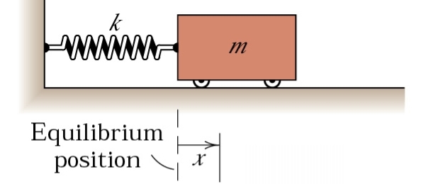
At any position x, we can draw a free body diagram of the mass and consider the forces that act on it.
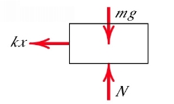
The mass is to the right of the rest position, thus x is positive, and so the spring applies a force on the mass to the left proportional to the stiffness and x, so F = kx. The self weight (mg) acting downwards and the normal force that the rollers exert to oppose this are included for completeness. If the mass had moved to the left, x would be negative and the restoring force F would act in the other direction.
Applying Newton's second law in the form  leads us to the equation of motion for this spring-mass system:
 One more manipulation of the equation of motion is necessary so that it takes the form of a second order ordinary differential equation:
d2x/dt2 + (k/m) x = 0
But instead we can write this as two first-order equations

Where the 'dot' represents d/dt and
This makes things much easier when there is damping, or when we want to simulate anything.
Key Takeaways:
We will illustrate the method the use of many examples.
When designing a shape or component, you normally need to manipulate its herbal vibration frequencies very carefully.
The oscillatory motions taken into consideration thus far had been for perfect structures, i.e. structures that oscillate indefinitely beneathneath the movement of linear restoring pressure. In actual structures, dissipative forces, along with friction, are gift and retard the movement.
Consequently, the mechanical strength of the gadget diminishes in time, and the movement is stated to be damped. One not unusualplace sort of retarding pressure is proportional to the velocity and acts withinside the route contrary to the movement.
The damping due to fluid friction is referred to as viscous damping. The presence of this damping is continually modelled through a dashpot, which includes a piston A transferring in a cylinder B as proven in Fig.
The frictional pressure is proportional to pace and is denoted through cx˙ and the consistent c is referred to as the coefficient of viscous damping.
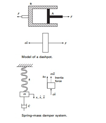
Consider the damped free vibration of a spring Ðmass damper system shown in Fig. Using D’Alembert’s principle, a dynamic problem can be converted to a static problem by considering inertia force.
Mx+cx+kx = 0 - - - - -3.1
Equation 3.1 is a linear, second order, homogeneous differential equation. It has the solution of the form
x = eλt 3.2
Substituting it in Eq. 3.2, we get
mλ2 + cλ + k = 0 3.3
Which has two roots given by
λ1, λ2 = - c/2m ±  3.4
3.4
Thus, the general solution of Eq. 3.4 is the sum of two exponentials λ1 and λ2. The critical damping coefficient is given by
cc = 2km 3.5
And = c/cc = damping factor 3.6
λ1 = - cc/2m +  3.7
3.7
λ1 = - n +  3.8
3.8
λ1 = n(- + 2 -1) 3.9 a
λ1 = n (- - 2 -1) 3.9b
And x = A eλ1t + Beλ2t 3.10
There are three special cases of damping that can be distinguished with respect to the critical damping coefficient.
Over-damped system
When c > cc and ρ > 1
x A eλ 1t Beλ 2t …. 3.11
There are two constants A and B which can be evaluated using initial conditions
xt=0 = x0; vt=0 = v0.
v = dx/dt = λ1 Aeλ1t + λ2Beλ2t 3.12
x0 = A + B 3.13a
v0 = λ1A + λ2B 3.13b
Solving the above two equations:
λ1 x0 = λ1A + λ2B
v0 = λ1A + λ2B
λ1x0 – v0 = B (λ1 – λ2)
B = (λ1x0 – v0)/(λ1 – λ2) ; A = (λ2x0 – v0)/(λ1 – λ2) 3.14
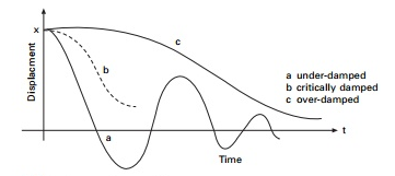
As t increases x decreases. This motion is non-vibratory or a periodic as shown in Fig.
Critically damped system
When c = cc and = 1 3.15
λ1 = - c/2m; λ2 = -c/2m 3.16a
1 = - n ; 2 = - n 3.16b
When we have two repeated roots
x = (A + Bt)e-nt 3.17
This motion is also non-vibratory but it is of special interest because x decreases at the fastest possible rate without oscillation of the mass and is shown in Fig.
Under-damped system
When c < cc and < 1. The roots shown in Eq. 3.7 are complex.
λ1 = n(- + i1-2) 3.18a
λ2 = n(- - i 1-2) 3.18b
x = A e-nt ei 1-2 tn + Be-nt e-i1- 2 tn 3.19
= e-nt (c1 sin n1-2 t + c2 cos n1-2 t) 3.20
Equation 3.20 may be written as
x = Ae-nt[sin (dt + )] 3.21
Again there are two constants, which can be evaluated using initial conditions x|0 = x0 ; v|0 = v0.
The constant ωd is defined as the damped natural frequency of the system, which is expressed as
d = n1 - 2 3.22
Where n = k/m
Is the natural frequency of the undamped vibration.
Equation 3.21 defines the harmonic oscillations of diminishing amplitude as shown in Fig. The amplitude is Aeρω n t
x = Aenτ [ sin(dt + )] 3.23 a
 n Ae-nτ [ sin (dt + )] + A e-ntd[ cos (dt +)] 3.23 b
At t = 0 x|t = 0 = x0 = A sin θ| 3.24a
 |t=0 = v0 = - nA sin + d A cos 3.24b
Or (v0 + n x0)/d = A cos 3.24c
Tan = dx0/(v0 + n.x0) 3.25
A = (x02 + (v0 + enx0)2/d) 3.26
x = e-τ[(v0+ n.x0)/n1 - 2 sin 1-2 nt + x0 cos 1-2 nt] 3.27
i.e. x = Xe-nt [sin (n1-2t + )] 3.28
A convenient way to determine the amount of damping present in a system is to measure the rate of decay of free oscillations. The larger the damping the greater will be the decay. Consider the damped vibration expressed by the general equation:
x = X e-nτ[sin (n 1 -2 t + )] 3.29
Which is shown graphically in Fig.
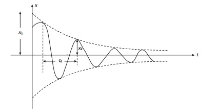
We introduce a term called logarithmic decrement defined as
δ = log x1/x2 = log Xe-nτ/Xe-n(τ + τd) = log enτd = nτd 3.30
τd = 2π/n(1 - 2) 3.31
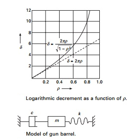
δ = (n2π)/n(1 - 2) = 2π/1 - 2 = logarithmic decrement 3.32
The above is an exact equation.
When is small
δ = 2π 3.33
Figure shows a plot of the exact and approximate values of δ as function of ρ.
From Eq. 3.31 it is seen that the period of the damped vibration τd is constant even though the amplitude decreases
τd = 2π/d
The period of damped vibration is always larger than the period of the same system without damping.
Example
A diesel engine generator of mass 1000 kg is mounted on springs with total stiffness 400kN/m. If the period of oscillation is 0.32s. Determine the damping coefficient c and damping factor ρ.
Given m = 1000 kg; k = 400 kN/m; T = 0.32.
Solution
T = 2π/n1 - 2 = 0.32 ; n = k/m
n = (400103/1000) = 20
0.32 = 2π/201- 2
1 - 2 = 2π/6.4 ; = 0.19
cc = 2km = 2 (400 103 1000) = 2 20 103
c = cc = 0.19 40 103
c = 7608 Ns/m
Example
A gun barrel weighing 5395.5N has a recoil spring of stiffness 300 000 N/m. If the gun barrel recoils 1.2 m on firing, determine
(a) the initial recoil velocity of the barrel;
(b) the critical damping coefficient of dash pot which is engaged at the end of recoil stage;
(c) the time required for the barrel to return to a position 50 mm from its initial position.
Solution
Weight of gun barrel = 5395.5 N, m = 550 kg, k = 300 000 N/m Kinetic energy = potential energy in the spring
½ mv12 = ½ kx2
½ 550 vi2 = ½ 300 000 1.22
vi = initial recoil velocity = 28.025 m/s
Cc = 2km = 2 (300 000 550) = 25690 Ns/m
Since it is critical damping:
x = e-wnt (A + Bt)
n = k/m = (300 000/550) = 23.35 rad/s
x = e-23.35 t (A + Bt)
At t = 0; x0 = - 1.2 m
t = 0; 
 e-23.35 t (A+Bt) + e-23.35tB
 |t = 0 ; A = 1.2 and B = -28.02
x = e-23.35 t ( - 1.2 – 28.02 t)
x = - 0.05 = e-23 . 35t (- 1.2 – 28.02 t)
Solving by trial and error t = 0.2135 second.
Forced vibration of single-degree-of-freedom system and vibration isolation
In many important vibration problems encountered in engineering work, the exciting force is applied periodically during the motion. These are called forced vibrations. The most common periodic force is a harmonic force of time such as
P = P0 sin ωt ………… 4.1
Where P0 is a constant, ω is the forcing frequency and t is the time. The motion is analysed using Fig. 4.1.

The general solution of Eq. 4.2 (non-homogeneous second order differential equation) consists of two parts x = xc + xp where xc = complementary solution,
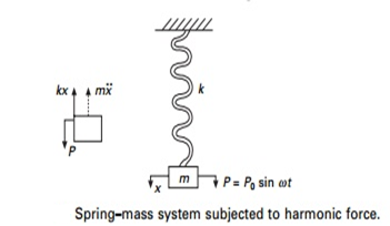
And xp = particular solution. The complementary solution is obtained by setting right hand side as zero.
 4.3
4.3
xc= c1 sin n t + c2 cos n t 4.4
Where n = k/m and c1 and c2 are arbitrary constants.
Assume cp = A sin wt and substituting
 4.5
4.5
(- 2 mA + kA) sin t = P0 sin t 4.6
A = P0/k(1 - 2 m/k) = P0/k(1 - 2/n2) 4.7
Since β = /n
A = P0/k(1 – β2) = (P0/k)/(1 – β2) 4.8
If P0 is applied statically, the static deflection
δst = P0/k 4.9
A = δst/(1 – β2) 4.10
The general solution of the forced vibration without damping is
x = xc + xP 4.11

The first two terms of free vibration are dependent only on properties m and k of the system and also on initial conditions. This is called transient vibration because, in a real system, it is damped out by friction.
The third term represents forced vibration and depends on the amplitude of applied force and forcing frequency ω (or β = ω/ωn).
This is called steady state vibration since it is the motion of the system after a transient vibration is dissipated.
Resonance: Steady state vibration
xp = δst sin t/(1 – β2) 4.13
The amplitude is δst/(1' β 2) and it becomes infinite when β = 1. This condition is called resonance.
Of course the amplitude does not become infinity in practice because of damping or physical constraints but the condition is a dangerous one, causing fractures. We define magnification factor as
MF = xP/δst = 1/(1 – β2) 4.14
And it is plotted as shown in Fig. Several items are of particular interest in this diagram.
Whirling of shaft and critical speed of rotors
Critical or whirling or whipping pace is the velocity at which the shaft has a tendency to vibrate violently with inside the transverse path. In different words, the velocity at which resonance happens are referred to as the crucial pace.
At crucial speeds, the amplitude of vibration of rotors is excessively massive and a massive quantity of pressure is transmitted to the bearings or foundations.
Therefore, it's miles vital to discover the herbal frequency of the shaft to keep away from the incidence of crucial speeds.
Causes of the Critical Speeds of Shafts
The crucial pace may also arise because of one or greater of the subsequent reasons:
Description When a rotor (say, a tools or a pulley) is installed on a desk bound shaft, its centre of gravity does now no longer normally coincide with the centre line of the shaft (axis of the shaft), as proven in Fig (a). Therefore, whilst the shaft rotates, it's miles subjected to a centrifugal pressure.
This in addition will increase the eccentricity, and as a result the centrifugal pressure. In this way, the impact is cumulative and in the end the shaft may also even fail.
The bending of shaft now no longer most effective relies upon the fee of eccentricity however additionally relies upon the velocity at which the shaft rotates. Thus the velocity at which the shaft has a tendency to vibrate violently withinside the transverse path is referred to as crucial or whirling pace.
Expression for Critical Speed
Consider a shaft of negligible mass wearing a rotor in among bearings A and B, as proven in Fig (a). Fig (b) suggests the shaft whilst rotating at a uniform pace of ω rad/s approximately the axis of rotation. Let factor O is at the shaft axis, O1 is geometric centre of rotor and ‘G’ is the centre of gravity of rotor.
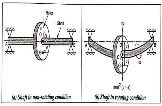
Let,
m = Mass of the rotor,
s = Stiffness of the shaft,
e = Eccentricity of the rotor i.e., distance between CG of rotor and geometric centre ‘O1‘,
y = Additional deflection of rotor due to centrifugal force, and
ω = Angular velocity of the shaft.
As shown in fig (b), the two forces acting on the rotor when it is rotating, are:
- Centrifugal force acting radially outwards through CG = m ω² (y+e)
- Force resisting the deflection (or restoring force) = s y
For equilibrium, Centrifugal force = Restoring force
∴m ω² (y+e) = s. y
Or m.ω².y + m.ω².e = s.y
y(s - m2) = m . 2 . e
Or y = (m . 2 . e)/(s – m . 2) = (2 . e)/(s/m - 2)
Or y = (2 . e)/(n2 - 2) [ n = s/m]
y = e/((n/)2 – 1)
Thus, when = n, the deflection y is infinitely large (and resonance occurs) and the speed is the critical speed.
Critical or whirling speed,
cr = n = s/m =g/δ] [ δ = m .g/s]
If Ncr is the critical whirling speed in r.p.s., then
Hence the critical or whirling speed of the shaft in r.p.s. Is equal to the natural frequency of transverse vibrations in Hz.
Key Takeaways:
At crucial speeds, the amplitude of vibration of rotors is excessively massive and a massive quantity of pressure is transmitted to the bearings or foundations.
References:
1. Theory of Mechanisms and Machines, Ghosh A. And Mallick A.K., Affiliated EastWest Press Pvt. Ltd., New Delhi, 1988.
2. Theory of Machines and Mechanisms, Shigley J.E. And UickerJ.J.,McGraw-Hill, Inc., 1995.
3. Mechanism and Machine Theory, Rao J.S. And Dukkipati R.V., Wiley-Eastern Limited, New Delhi, 1992.
4. Mechanics of Machines, John Hannah and Stephens R.C., Viva Books.
5. Theory of Machines, Sadhu Singh, Pearson Education.