Unit - 2
Draught and its classification
Draught and its classification
BOILER DRAUGHT:
Draught, suggested as 'draft' is the distinction of pressures, maintained above and beneath the hearth place grate.
It is one of the maximum critical structures of a thermal strength plant. The cause of draught is to deliver required amount of air for combustion of gasoline and additionally to get rid of the burnt (flue) gases from the boiler.
Definition: Boiler draught is the small distinction of strain among strain of air outdoor and that of gases inside a furnace.
Functions of Draught:
In a. Boiler, draught may be produced through a chimney, fan, air jet etc., Functions of draught are –
- To pressure air thru the gasoline mattress to resource right combustion. –
- To attract ensuing warm gases thru the gadget –
- To get rid of merchandise of combustion to the environment once they have given out their warmness to water being evaporated
Classification of Draught (Methods of Producing Draught):
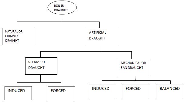
Steam Jet
Draught can be triggered one or compelled draught. Mechanical (Fan) Draught is in addition sub-divided as, Induced Draught, Forced Draught and Balanced Draught. The type of boiler draught is schematically represented as shown.
Natural Draught (Chimney Draught):
Natural draught is produced through a chimney.
Hot gases produced with inside the combustion chamber of boiler are discharged out thru this chimney excessive into environment to keep away from air pollutants and on the equal time to provide draught with inside the boiler. The draught produced through the chimney is because of the temperature distinction and therefore density distinction of warm gases with inside the chimney and bloodless air outdoor the chimney. Before firing the boiler, atmospheric strain in any respect factors alongside the grate travel (Figure) might be the equal (say pa). Pressure at point (2) (say p2) is much less than pa on the grounds that atmospheric strain decreases with the attitude.
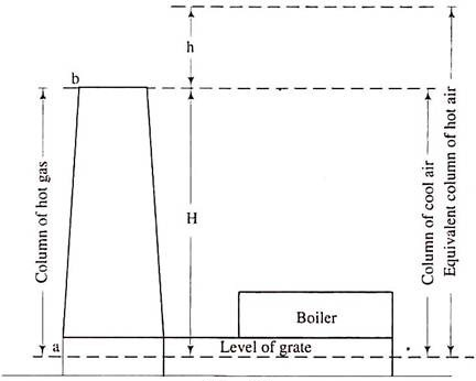
Now when the boiler is fired, hot gases will fill up the chimney. Pressure pi at grade level (F) and pressure p2 at top of chimney remain unaffected. But pressure at the base of chimney, PA drops and is given by,
PA = P2 + wgH
Wg = weight density of hot gases
PA < P3
H = altitude of chimney and p1 = p2 + waH
We = weight density of atmospheric air
Let Δp = pi - pA
= H (wa— wg) =
Theoretical maximum static draught
Advantages: -
- Natural draught does now no longer require any outside strength –
- Cost involvement is much less. –
- Maintenance value is sort of nil –
- Cleanliness is ensured –
- Minimizes pollutants of air –
- It has lengthy life –
- Best perfect for small plants
Limitations: -
- The most strain to be had for generating herbal draught is rarely 10 to twenty mm of water –
- Available draught decreases with the growth of outdoor air temperature –
- Greater quantity of warmth usage from warm gases isn't feasible on the grounds that discount in temperature of flue gases lessen draught –
- No flexibility with inside the gadget to create extra draught –
- Because of low pace of air, combustion is terrible and unique gasoline intake of the plant increases –
- Structural constraints restriction the peak of chimney
Draught losses:
- The losses in boiler draught can be because of the subsequent reasons. –
- The frictional resistance among flue (exhaust) gases and chimney walls –
- The bends with inside the fuel line float path –
- The friction head in system like grate, economizer, superheated etc., -
- Draught loss in chimney is set 20% of overall draught produced through it.
Artificial Draught:
Total static draught required varies from 25 to three hundred mm of water in huge steam strength plants. It isn't handy to construct a completely tall chimney that could produce this type of massive draught. It isn't in your price range additionally.
Moreover herbal draught is depending on climatic conditions. Its cost decreases whilst outdoor temperature is higher. A synthetic draught produced through lovers or blowers overcomes those drawbacks.
Advantages of Artificial Draught: -
It does now no longer rely on climatic conditions –
Inferior high-satisfactory of gasoline may be economically burnt - High temperature of flue gases as important for herbal draught isn't required.
This allows extra utilization of warm gases in Economizer, Super heater, Air pre heater etc. –
Chimney top may be drastically reduced –
Artificial draught may be regulated in line with furnace requirement –
Efficiency is a great deal extra than that of herbal draught.
Steam Jet Draught:
Steam Jet Draught is one of the only and most inexpensive strategies of manufacturing synthetic draught. The exhaust steam from a non-condensing steam engine is discharged thru a blast pipe located the chimney at excessive pace. This produces a draught. It is in the main used it locomotives.
In a triggered steam Jet Draught the steam jet issuing out from a nozzle is located with inside the chimney. In a compelled Ni swam jet draught, the jet is located in an ash pit below the hearth place grate of the furnace.
Advantages:
- Easy and in your price range –
- Occupies minimal space –
- Calls for little or no attention –
- Low grade gasoline may be used
Mechanical Draught of Fan Draught:
(A) Induced Draught:
This result in pressure drop with in the furnace below the atmospheric pressure. Hence atmospheric air flows via the furnace freely. The movement of the precipitated draught with in the furnace is similar to the movement of the chimney. The draught produced in this device is impartial of the temperature of the latest gases.
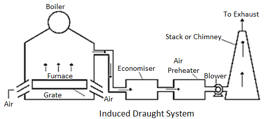
Hence the flue gases can be discharged as bloodless as feasible after improving their warmness in economizer and air-preheater.
(B) Forced Draught:
In this technique, a blower is located earlier than the grate and air is compelled into the grate thru the closed ash pit. This compelled air passes thru the furnace, economizer, air preheater and chimney.
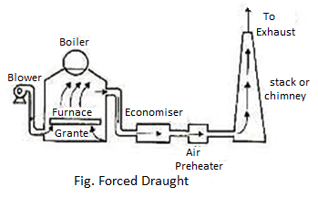
Compelled draught.jpg in this gadget strain of air stays above atmospheric throughout. It is, therefore, referred to as superb draught gadget or compelled draught gadget. A stack or chimney is likewise used as a way to discharge out flue gases excessive into environment, for that reason decreasing pollutants.
Induced Draught Vs. Forced Draught:
The quantity of gases dealt with through I.D. Fan is a great deal large than compelled draught fan because of excessive temperature of gases with inside the I.D. Gadget.
The length and strength required through I.D. Fan is extra than the ones of F.D. Fan. To face up to excessive temperature of flue gases I.D. Lovers are to be furnished with water cooled bearings. There is an opportunity of air leakage into the furnace in I.D. Structures because the strain with inside the furnace is much less than the atmospheric strain.
This impacts combustion. But there's no danger of air leakage in compelled draught gadget. In FD. Gadget float of air thru the grate and furnace is extra uniform and for this reason charge of burning increases.
Balanced Draught:
In a compelled draught too, whilst the furnace doorways are opened, the excessive strain air with inside the furnace will blow out abruptly and there's an opportunity of extinction of lire.
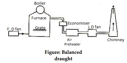
To triumph over those drawbacks a balanced draught is used. It is an aggregate of each the triggered and compelled draughts.
Advantages of Mechanical Draught:
Following are the benefits of mechanical draught over herbal draught. –
- Easy manipulate of combustion and evaporation –
- Increase in evaporative ability of boiler. –
- Plant performance increases. –
- Reduced chimney top –
- Capability of eating low grade gasoline –
- Prevention of dense smoke. –
- Fuel intake reduces through 15% relative to herbal draught gadget. –
- Leakage of air into boiler furnace is reduced.
Calculations for chimney height
This idea primarily based totally on our Engineering enjoy in Thermal energy plant. It turned into found out all through 1980’s to 1990’s to satisfy pollutants manipulate norms and Limitations, chimney heights had been unexpectedly expanded to 220meters and 275 meters ( 500 MW and above) with ESP Outlet Dust Burden as 150mg/Nm3.
The fundamental reason being pollutants to be discharged at a sizable peak such that dispersion take location over an extensive area , their attention on accomplishing the floor might fulfill the stern prerequisites of pollutants regulatory standards .
Execution of labor at sizable heights now no longer handiest posed techno monetary issues to the contractors however additionally require current state-of-the-art layout gear and creation techniques (slip form).
The gift take a look at is made to lessen chimney peak thinking about all of the pollutants tiers and decreased the development value and creation time. With the today's current technology, pollutants manipulate system “Electrostatic Precipitator (with excessive Efficiency 99.9% “has been evolved to keep outlet flue fuel line dirt tiers much less than 50mg/Nm3 /hr. In maximum of the international locations ESP were designed and operational to keep outlet dirt burden much less than 50 mg/Nm3 aside from this Flue fuel line de suphurization system additionally be established to manipulate SOx tiers.
The capacity of a chimney depends on the potential chimney draft - the pressure difference created by the inside and outside air temperature difference and chimney height - and the chimney area.
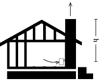
The pressure difference in the chimney pulls air and fuel gas from the boiler or fireplace through the chimney and out of the building.
Chimney Draft
The pressure difference or chimney draft can be expressed as:
Dpch = h (ρo - ρi) ag (1)
Where
Dpch = pressure draft in the chimney (Pa)
h = height of chimney (m)
ρo = ambient outside density of air (kg/m3)
ρi = inside chimney density of air (kg/m3)
ag = acceleration of gravity (9.81 m/s2)
Since the Ideal Gas Law states that
ρo To = ρi Ti
Or
ρi = ρo To / Ti (2)
Where
T = t + 273 = absolute temperature (K)
Where
t = temperature (°C)
- (1) can alternatively be expressed as:
Dpch = h (ρo - ρo To / Ti) ag
Or
Dpch = h ρo ( 1 - To / Ti) ag
Chimney diameter & efficiency
When coal, oil, herbal fuel line, timber, or some other gasoline is combusted in a stove, oven, fireplace, warm water boiler, or commercial furnace, the new combustion product gases which can be fashioned are known as flue gases.
Those gases are typically exhausted to the ambient outdoor air via chimneys or commercial flue fuel line stacks (occasionally known as smokestacks).
The combustion flue gases with inside the chimneys or stacks are a good deal warmer than the ambient outdoor air and consequently much less dense than the ambient air
That better strain outdoor the chimney is the using pressure that actions the desired combustion air into the combustion sector and additionally actions the flue fuel line up and out of the chimney.
There may be instances of diminishing returns:
If a stack is overly tall when it comes to the warmth being dispatched out of the stack, the flue gases might also additionally cool earlier than accomplishing the pinnacle of the chimney.
This circumstance can bring about terrible drafting, and with inside the case of timber burning appliances, the cooling of the gases earlier than emission can purpose creosote to condense close to the pinnacle of the chimney.
The creosote can limitation the go out of flue gases and can pose a hearth place hazard.
As a "first guess" approximation, the subsequent equation may be used to estimate the herbal draught/draft waft price via way of means of assuming that the molecular mass (i.e., molecular weight) of the flue fuel line and the outside air are identical and that the frictional strain and warmth losses are negligible:
Q = C A 
Where:
- Q = chimney draught/draft flow rate, m3/s
- A = cross-sectional area of chimney, m2 (assuming it has a constant cross-section)
- C = discharge coefficient (usually taken to be from 0.65 to 0.70)
- g = gravitational acceleration, 9.807 m/s2
- H = height of chimney, m
- Ti = average temperature inside the chimney, K
- Te = external air temperature, K.
Combining two flows into chimney: At+Af<A, where At=7.1 inch2 is the minimum required flow area from water heater tank and Af=19.6 inch2 is the minimum flow area from a furnace of a central heating system.
Efficiency:
It may be smooth to overlook to shut it while the hearth place has burned out, however retaining the damper open can purpose drafts and warmth loss with inside the relaxation of the house.
Install tempered glass doorways and a heat-air alternate gadget that blows heat air lower back into the room.
Check the seals round your fireside flue damper—if the seals aren’t tight, you may be dropping domestic heating via the chimney.
- Insulate your chimney.
- Liners offer most performance in your chimney and defend masonry from corrosive byproducts of the flue gases.
- Get your chimney well inspected with the aid of using a chimney sweep.
- A licensed chimney sweep can provide recommendation to assist ensure all of the additives of your fireside and chimney are functioning successfully and safely.
Draught (h) required in mm of water
h = 353 H [ 1/Tn – (ma+1)/ma 1/Tg] mm of water
ma = mass of air required to in kg/kg of fuel
Ta = absolute temperature of atmosphere
Tg = average absolute temp of chimney gases
H = height of chimney
Draught in terms of hot gas colum (H’) is given as
H’ = H [ ma/(ma +1) Tg/Ta – 1] meters of hot gases
For maximum discharge
Tg/Ta = 2(ma+1)/ma
Using value in the equation for draught in terms of water column
H’ = H [ ma/(ma + 1) 2(ma +1)/ma – 1] = H
Height of gas column required = H = height of chimney
Key takeaways:
- Steam Jet Draught is one of the only and most inexpensive strategies of manufacturing synthetic draught.
- The quantity of gases dealt with through I.D. Fan is a great deal large than compelled draught fan because of excessive temperature of gases with inside the I.D. Gadget.
- To triumph over those drawbacks a balanced draught is used. It is an aggregate of each the triggered and compelled draughts.
Condition for maximum discharge
Condition for maximum discharge through nozzle:
The nozzle is always designed for maximum discharge
m/A = 
The mass flow per unit area will be maximum at the throat because the throat area is minimum.
It is seen from the above equation that the discharge through a nozzle is a function of P2/P1 only, as the expansion index is fixed according to the steam supplied to the nozzle.
Therefore, n/A is maximum when
 is minimum
This means m/A =f (P2/P1).
To get its maximum value we have to differentiate m/A w.r.t. P2/P1 and equate it to zero.
So after manipulation the ratio between the critical pressure and the initial pressure for a nozzle can be expressed as
P2/P1 = [2/(n+1)]n/(n – 1)
Putting this value in the mass flow rate equation, we get
m = A 
We know P2/P1 = (2/n+1)n/n+1
Putting the value of P2/P1 in the above equation
mmax = A
mmax = A
= A
= A
= A
= A
mmax = = A
Where P1 is the initial pressure of the steam in kpa and v1 is the specific volume of the steam in m3/kg at the initial pressure.
Problem Solving:
1. Steam at 10.5 bar and 0.95 dryness is expanded through a convergent divergent nozzle. The pressure of steam leaving the nozzle is 0.85 bar.
Find i) velocity of steam at throat for maximum discharge, ii) the area at exit iii) steam discharge if the throat area is 1.2cm2. Assume the flow is isentropic and there are no friction losses.
Take n= 1.135.
Given data:
P1 = 10.5 bar
P2 = 0.85 bar
Area at throat At = 1.2 cm2 x1 = 0.95
n = 1.135
Solution:
We know that, for n = 1.135
Throat pressure Pt = 0.577 x P1 = 0.577 x10.5 = 6.06 bar
Properties of steam from steam tables:
At P1 = 10.5 bar hf = 772 KJ/kg
sf = 2.159 KJ/kg
hfg = 2006 KJ/kg
sfg = 4.407 KJ/kg
At Pt =6.09 bar hr = 673.25 KJ/kg
sf = 1.9375 KJ/kg
hfg = 2082.95 KJ/kg
sfg = 4.815 KJ/kg
vf = 0.01101 m3/kg
vg = 0.31556 m3/kg
P2 = 0.85 bar hf = 398.6 kJ/kg
hfg = 2269.8 kJ/kg
sf = 1.252 kJ/kgk
sfg = 6.163 kJ/kgk
vf = 0.001040 m3/kg
vg = 1.9721 m3/kg
So, s1 = s0 + x1 xsfg
= 2.159 + 0.95 4.407 = 6.34565 kJ/kg
h1 = hf1 + x1 hfg1
= 772 + 0.95 4.407 = 6.34565 kJ/Kgk
1-t isentropic expansion between inlet and throat
So s1 = sf = 6.34564 kJ/kg
s1 = sa + xf sfgt
6.34565 = 1.9375+ x1 4.815
xt = 0.915
ht = hft + x1 hfgt
= 673.25 + 0.915 2082.95
=2579.15 kJ/kg
Velocity of steam at throat:
Vt = [2000× (h1-ht)] 1/2 = 443.96 m/s vt =
Xt x vgt =
0.915 x 0.31156 =
0.2887 m3 / kg
Mass of steam discharged:
m = At Vt/vt = 1.2 10-4 443.96/0.28874
= 0.1845 kg/s
t – 2 isentropic expansion between throat and exit
st = s2 = 6.34565 kJ/kgk
6.34565 = 1.252 + x2 6.162
x2 = 0.83
v2 = 0.83 1.9721 = 1.637 m3/kg
h2 = 398.6 + 0.83 2269.8
= 2282.534 kJ/kg
Velocity of steam at exit
V2 = 2000 (h1 – h2)
= 2000(2677.7 – 2282.534)
= 889 m/sec
According to mass balance, steam flow rate of throat is equal to flow rate at exit
mt = m2 = A2 V2/v2 = A2 889/1.637
0.1845 1.637/889 = A2 = 3.397 10-4m2
Performance of steam generators
Ideally, superheat energy is almost completely consumed at the last, low-pressure turbine blades.
The West Co-Gen Plant on the University of Illinois at Chicago (UIC) produces heating steam for the west facet of the university campus, which include about 50 homes and the college hospitals (UIC and Rush). It additionally generates chilled water for the west campus and the UIC sanatorium.
However, as several plant proprietors and operators have discovered, frequently to superb regret, if plant make-up and procedure waters aren't handled nicely to put off impurities and optimize chemistry, extreme corrosion, scaling, and fouling are the result.
At UIC, a lot development has been made in the direction of enhancing water/steam chemistry during the last decade, with extra efforts ongoing.
This article outlines numerous of those upgrades and a number of UIC’s destiny dreams for water/steam chemistry remedy.
Facility Description UIC, based with inside the overdue nineteenth century, has an enrollment of almost 30,000 college students and operates the most important clinical college with inside the country.
Such an intensive campus and clinical centers require full-size portions of steam for heating and chilled water for cooling.
For many years, steam on the West plant turned into produced via way of means of six 1950s-technology Babcock & Wilcox boilers. Three of those boilers had been retired in place, however the different 3 are nonetheless operational.
The plant additionally has a 5-year-antique Victory boiler (180,000 lb/hr. Steaming charge most) that facilitates to deliver steam potential and backup skills at some point of the bloodless iciness months in Chicago.
Too many years ago, the plant moved to co-technology with the setup of 3 sun fuel line turbines, every able to 7-MW energy production. The turbine exhaust gases energy 3 warmth recuperation steam turbines (HRSGs).
During regular operation, every HRSG can produce 30,000 lb. /hr. Of steam, however the steaming charge may be expanded to 120,000 lb/hr with duct firing. Co-technology gives a lot better internet efficiencies than stand-by myself steam production, and is turning into more and more famous for lots applications.1 Superheated steam (430°F to 450°F) at 143 to a hundred forty five psig is furnished to an inlet header, which then feeds the distribution traces to the campus. Much of the condensed steam is recovered, with a most condensate go back of round eighty five percentage. Chiller gadget includes seven York Chillers, with 3 2,500-ton potential gadgets and 4 2,000-ton machines. System extent is seven hundred, 000 gallons, and the chillers feed the whole campus besides for Rush Hospital
Evaporation capacity
Evaporation is the elimination of solvent as vapor from an answer, slurry or suspension of stable in a liquid. The goal is to pay attention a non-risky solute, which include organic compounds, inorganic salts, acids or bases from a solvent.
Evaporation differs from the alternative mass switch operations which include distillation and drying. In distillation, the additives of an answer are separated relying upon their distribution among vapor and liquid levels primarily based totally at the distinction of relative volatility of the substances.
Removal of moisture from a substance in presence of a warm fuel line move to hold away the moisture leaving a stable residue because the product is commonly referred to as drying.
Evaporation is commonly stopped earlier than the solute begins off evolved to precipitate with inside the operation of an evaporator. Invention of evaporators:
Norbert Rillieux is well-known for his invention of the couple of impact pan evaporator for sugar refining technique in 1881. Rillieux became born in New Orleans, Louisiana in 1806. He used the steam generated from one pan to heat the sugar juice with inside the subsequent pan for power green manner of water evaporation.
Because the boiling factor of magnesium is decrease than that of different factors with inside the system of magnesium alloy welding, it is straightforward to volatilize and segregate magnesium with inside the weld bath.
Hence, it's miles very critical to observe the boiling factor of magnesium alloys to decide the precise alloy composition for engineering applications. There are many techniques for measuring the boiling factor.
When the vapor stress is more than 1 torr (1 mmHg), direct measurement, segment transition or air current-sporting techniques may be adopted. Hence, for a sure atmospheric stress, the boiling factor may be described through the connection among the evaporation potential and the temperature. To degree the boiling factor, the subsequent technique may be used: preserving the stress of the gadget constant, converting the temperature of a pattern incrementally, after which measuring the corresponding alternate of the pattern in phrases of weight or different property.
When an unexpected alternate occurs, that is the boiling factor (segment transition factor).
For measuring of the boiling factor, the stress of the gadget is ready identical to the atmospheric stress that is a constant.
Then, the burden alternate of the pattern with incremental alternate in temperature is measured.
The temperature at which the burden unexpectedly adjustments is the boiling factor of the pattern.
This is named the weight reduction technique. The have an impact on of numerous not unusual place alloying factors, particularly Al, Zn, Mn and La, at the boiling factor of magnesium, has been investigated and compared.
Equivalent evaporation
Equivalent evaporation = evaporation from and at 100°C. Evaporation figures hence expressed dispose of the consequences of various feed water and superheat temperatures, and are consequently a real degree of evaluation among unique boilers.
This defines it in phrases of kg (of water/steam) consistent with kJ of strength.
However it's far from time to time described in devices of kg water consistent with kg of fuel, and (as with inside the case of the graph above) kg water/steam consistent with hour.
The wide variety of kg of water evaporated consistent with hour in no manner offers the precise manner for evaluation of the overall performance of the boilers. Hence to examine the evaporative potential or overall performance of various boilers operating below unique situations it turns into vital to offer a not unusual place base in order that water be pre purported to be evaporated below well-known situations.
The well-known situations followed are: Temperature of feed water 100°C and transformed into dry and saturated steam at 100°C. As consistent with those well-known situations 1 kg of water at 100°C necessitates 2257 kJ (539 kcal in MKS devices) to get transformed to steam at 100°C.
“Thus the equal evaporation can be described as: the quantity of water evaporated from water at 100°C to dry and saturated steam at 100°C.
“Consider a boiler generating ma kg of steam per hour at a pressure p and temperature T.
Let h = Enthalpy of steam per kg under the generating conditions.
- h = hf + hfg ……. Dry saturated steam at pressure p
- h = hf + xhfg ……. Wet steam with dryness fraction x at pressure p
- h = hf + hfg + cp (Tsup – Ts) ….. Superheated steam at pressure p and temperature Tsup
- hf1 = Specific enthalpy of water at a given feed temperature.
Then heat gained by the steam from the boiler per unit time = ma x (h – hf1)
The equivalent evaporation (me) from the definition is obtained as:
DS/dEb = k1/k2 – 2Eb/k2 = 0
For comparing the capacity of boilers working at different pressures, temperatures, different final steam conditions etc, a parameter called “equivalent evaporation” can be used. Equivalent evaporation actually indicates the amount of heat added in the boiler for steam generation. Equivalent evaporation refers to the quantity of dry saturated steam generated per unit of time from feedwater at 100°C to steam at 100°C at the saturation pressure corresponding to 100°C. Sometimes it is called equivalent evaporation from and at 100°C. Thus mathematically it could be given as:

For a boiler generating steam at ‘m’ kg/h at some pressure ‘p’ and temperature ‘T’, the heat supplied for steam generation = m x (h – hw), where h is the enthalpy of final steam generated and hw is enthalpy of feedwater. Enthalpy of final steam shall be:
- h = hf + hfg = hg for final steam being dry saturated steam (hf, hfg and hg are used for their usual meanings),
- h = hf + x . hfg for wet steam as final steam,
- h = hg + cp sup.steam . (Tsup – Tsat) for superheated final steam.
Equivalent evaporation (kg/kg of fuel) = m.(h - h)/539
Equivalent evaporation is thus a parameter which could be used for comparing the capacities of different boilers.”
Boiler efficiency
Boiler performance is a blended end result of efficiencies of various additives of a boiler. A boiler has many sub structures whose performance influences the general boiler performance.
Couple of efficiencies which eventually determine the boiler performance are-
- Combustion performance
- Thermal performance
Apart from those efficiencies, there are a few different losses which additionally play a function at the same time as figuring out the boiler performance and consequently want to be taken into consideration at the same time as calculating the boiler performance.
Combustion Efficiency
The combustion performance of a boiler is the indication of burner’s capacity to burn gasoline. The parameters which decide the burner performance are unburnt gasoline portions in exhaust and extra oxygen stages with inside the exhaust.
This outcomes in decreasing the unburnt gasoline losses however raising the enthalpy losses. Hence, it's far pretty crucial to preserve a stability among enthalpy losses and UN burnt losses.
Combustion performance additionally varies with the gasoline being burnt. Combustion performance is better for liquid and gaseous fuels than for strong fuels.
Thermal Efficiency
The thermal performance of a boiler specifies the effectiveness of the warmth exchanger of the boiler which simply transfers the warmth electricity from hearth to water side.
Thermal performance is improperly laid low with scale formation/soot formation at the boiler tubes.
Direct and Indirect Boiler Efficiency
The standard boiler performance relies upon on many greater parameters other than combustion and thermal efficiencies.
These different parameters encompass ON-OFF losses, radiation losses, and convection losses, blow down losses etc. In real practice, techniques are usually used to discover boiler performance, specifically direct approach and oblique approach of performance calculation.
Direct efficiency
This method calculates boiler efficiency by using the basic efficiency formula-
η=(Energy output)/(Energy input) X 100
In order to calculate boiler efficiency by this method, we divide the total energy output of a boiler by total energy input given to the boiler, multiplied by hundred.
Calculation of direct efficiency-
E= [Q (H-h)/q*GCV]*100
Where,
Q= Quantity of steam generated (kg/hr)
H= Enthalpy of steam (Kcal/kg)
h= Enthalpy of water (kcal/kg)
GCV= Gross calorific value of the fuel.
Indirect Efficiency
The oblique performance of a boiler is calculated through locating out the man or woman losses taking region in a boiler after which subtracting the sum from 100%. This approach entails locating out the magnitudes of all of the measurable losses taking region in a boiler through separate measurements. All those losses are introduced and subtracted from 100% to discover the very last performance. Blow down valve is saved closed at some stage in the procedure. This approach must be applied as consistent with the norms supplied in BS845 standards. The losses calculated encompass stack losses, radiation losses, blow down losses etc.
Comparison of direct and oblique performance- Both the techniques of locating out boiler performance stated above have a few benefits and a few risks related to them.
By locating out oblique performance, you can still come to realize wherein the losses are accelerated and may be reduced. On the alternative hand, direct performance values are toward fact compared to oblique performance as a result of exposed losses together with radiation losses, ON-OFF losses etc. But direct performance can best inform us approximately the significance of standard loss. No statistics approximately man or woman losses and their magnitudes is conveyed from direct performance calculation.
There usually exists a few distinction with inside the values of direct and oblique efficiencies.
Indirect performance is measured at a specific time while direct performance is measured over a time period and consequently, losses as a result of fluctuating loads, boiler on-off etc. also are taken into consideration.
Real time performance tracking
Boiler performance does now no longer continue to be constant and big versions from perfect values take region at some stage in the path of operation. Shifting to actual time performance tracking can enhance the boiler performance considerably relying upon the boiler kind and real situations at site. In nutshell, tracking and keeping the boiler performance for the general operational existence of the boiler is a need to reduce gasoline payments and decrease carbon footprint.
Key Takeaways:
- At UIC, a lot development has been made in the direction of enhancing water/steam chemistry during the last decade, with extra efforts ongoing.
- However it's far from time to time described in devices of kg water consistent with kg of fuel, and (as with inside the case of the graph above) kg water/steam consistent with hour.
References:
1. Thermal Engineering, Mathur &Mehtra, Jain Brothers Publications, New Delhi.
2. Heat Engineering, V.P. Vasandani& D.S. Kumar, Metropolian Book Publishers.
3. Power Plant Engineering, A.K. Raja, Shrivastava and Dwivedi, New age International Publishers.
4. Fluidized Bed Combustion, S. Oka and E. Anthony, Marcel Dekker Inc.
5. Power Plant Engineering, M. M. EI- Wakil, McGraw Hill International.