UNIT 1
Prestressed concrete- analysis
The idea of prestressed concrete is not new and it has been used in various ways since ancient times. To explain the idea of prestressed concrete some of the very well known examples are given here with.
Example number 1
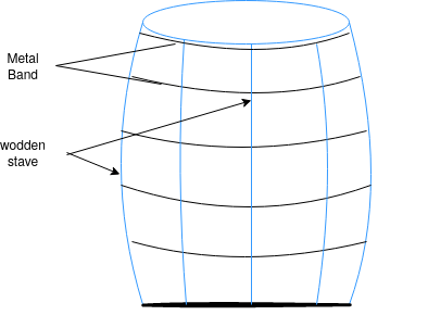
Consider a wooden barrel construction by forcefully fit metal bands around it. Now if this barrel is filled with some liquid which produces internal pressure on the internal surfaces of barrel inducing the hoop tension in wood. However, the forcefully tightened bands which are initially producing the compression in the barrel material will be able to resist the hoop tension produced by liquid inside the barrel.
Example number 2
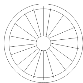
Consider a wooden wheel of bullock cart in which the wooden spokes are subjected to initial tension by shrink fitting (after heating) of metal tyres. Now, when the cart is loaded it produces the compression in the spokes. Some example can be given for the spokes of bicycle or two wheeler in which riders weight producing compression is balanced by the initial tension due to tightening of spokes between the axle and the rim thus the principle depicted in above examples is used in prestressed concrete.
Strength of concrete in weak in tension, hence it is ignored in reinforced concrete design. In RCC design assume compressive force resist in concrete and tensile force resist in steel i.e. reinforced we know stress strain diagram R.C. Beam
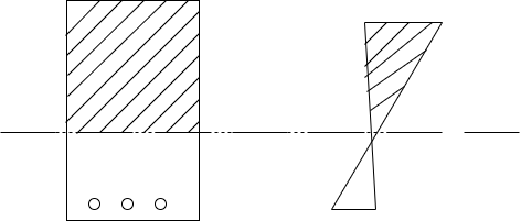
In this diagram concrete above neutral axis is useful in resisting applied load while the concrete below neutral axis is not useful in resisting any load. The concrete in tension side only acting as a cover to reinforcement only. This disadvantage of RCC, made the concrete lover to think of improving the use of concrete and it resulted into development of prestressed concrete.
Prestressed concrete is that can create in which the compressive stresses are induced in the concrete section before the member is loaded by external loads.
IS code-1343-2012; concrete in which permanent internal stresses are deliberately introduced usually by tensioned steel, to counteract to the desired degree the stresses caused in the member in service.
Need of prestressing a concrete member
Concrete which is strong in compression but weak in tension; however concrete is very weak in tension and it is very difficult to have concrete of tensile strength greater than 2.5 
In RCC use concrete and reinforcement bonded to perfect bond. Due to loading cracks get developed in concrete as the steel yields.
In prestressing concrete member reduces these deflects and use high strength concrete and high tensile steel i.e. tendon.
Table-1:Comparison between prestressed and RCC
R.C.C. | Pre-stressed |
30% to 40% of total cross-sectional area is utilized | Hundred percent cross-sectional area is utilized |
Section is an economical beyond spans of 10m to 12m (load heavy) | Economical up to spans of 25 to 30 m (load small) |
Self weight of section is higher | Self weight of section is lesser |
Cracking and corrosion problems are more | No cracking and corrosion problems |
Reinforcement is straight | Reinforcing tendons can be bent or have parabolic shapes |
Tension is developed below neutral axis | The whole cross section is in compression |
Stresses are developed only after external load is allowed | Stresses are developed before counting due to pre compressive load |
Generally large in size and require additional share reinforcement to resist shear forces | In P.C. Section are smaller in size and due to pre stressed tendon a considerable amount of shear reinforcement is avoided |
It does not require any auxiliary units much for construction | Auxiliary units are required live anchoring devices, equipments for prestressing |
The terms commonly used in prestressed concrete are explain the terms are placed in group as per usage
a) Forms of prestressing steel:-
1) Wires:- prestressing wire is a single unit made of steel.
2) Strands:- 2, 3 or 7 wires are wounds to form a prestressing strands.
3) Tendon:- a group of strands or wires are wounds to form a prestressing tendon.
4) Cable:- a group of tendons forms a prestressing cable.
5) Bars:- tendon can be made up of a single steel bar the diameter of bar is much larger than that of a wire.
b) Nature of concrete steel interface:-
1) Bonded tendon:- when there is adequate bond between the prestressing tendon and concrete, it is called as bonded tendon. Pre-tensioned and grouted post tensioned tendons are bonded tendons.
2) Unbonded tendon:- when there is no bond between the prestressing tendon and concrete, it is called as bonded tendon. When grout is not applied after post-tensioning the tendon is an unbounded tendon.
c) Stages of loading:- the analysis of pre-stressed member can be different for the different stages of loading. The stages of loading are as follows:
1) Initial:- it can be subdivided into two stages
a) During tension of steel
b) At transfer of prestress to concrete
2) Intermediate:- this includes the loads during transformation of the prestressed members.
3) Final:- it can be subdivided into two stages
a) At service, during operation
b) Add ultimate comedy during extreme events
Why high strength concrete used in prestressed concrete
1) High strength concrete is having low shrinkage and creep value, high impermeability, high resistance to abrosion and more ductility.
2) High strength concrete permits hire bond between steel and concrete because stresses transformed from tendons to concrete.
4) It has high modulus of elasticity leading to smaller elastic strain when tendons are cut. This will reduce relaxation loss in steel.
5) Use of high strength concrete is justified in terms of cost also, as in prestressed concrete the entire cross section is in compression and hence full concrete area is utilised in resisting compressive force.
6) To sustain the high stresses at anchorage regions, due to large prestressing force to be applied by tendon.
7) To have higher stiffness for reduced deflection.
8) In factories, with high degree of control it is easier to produce high strength concrete.
9) For post tensioned prestress concrete, the grade of concrete shall not be less than  However for pre tensioned concrete is shall not be less than
10) High strength concrete will have modulus of elasticity of concrete  [ IS-1343-2012,clause no 6.2.3.1 ,pp-5]
11) Hence elastic and cracks trains are very low resulting in smaller loss of prestressing force.
12) Just of high strength concrete reduces the size of concrete member thereby resulting in of concrete in reduction of self weight of the member.
Why high strength steel used in prestressed concrete
1) A large prestressing force can be developed on smaller steel area, there force, high tensile strength wires, strands and tendons used in prestressing members.
2) When concrete shortens due to compressive stress, creep and shrinkage, a large amount of prestress is lost. If high tensile bars are used for prestressing, permitting a large initial prestress, the loss of prestress will be small percentage of total initial prestress.
3) For post tensioned structures, anchorage regions have concentrated and very high stresses.
4) High tensile steel give high bond strength to avoid slippage.
Advantages of prestressed concrete
1) This provides a type of construction which is always free from cracks under full working load. Due to this reason, such type of construction is suitable where corrosion is a great danger.
2) Sufficient horizontal compression due to prestress reduces principal tensile stresses and shear resistance is developed without heavy reinforcement of large webs.
3) Less steel is used in the members, it is easier to place good quality of concrete with high compressive strength than in the case of reinforced concrete.
4) This type of construction saves material as well as dead loads and hence considerable savings in supports and foundations is also achieved.
5) Smaller sections are used in this type of construction. For this reason very large spans can be built in prestressed concrete then in reinforcement concrete.
6) For precast prefabricated construction the advantages of a reduction in self weight of the unit are obvious. Also prestressing counteracts handling stress. Hence we can use this method for precast work.
7) The cost of shuttering and centring in large structures is reduced when prestressed precast elements are assembled.
8) The amount of steel required is very low.
9) Deflections of structures are reduced.
10) The time of construction is much less if precast prestressed members are used.
Disadvantages of prestressed concrete
1) It requires high tensile steel and high strength concrete of grades more than  And above. Hence it will become more expensive for small jobs.
2) Prestressing is a tedious job. It requires expertise supervision.
3) Cables are required to be anchored by mechanical means. However, full prestressing force cannot be obtained due to losses in prestress to the extent of 25%.
4) Special prestressing techniques are required for both pre tensioned and post tensioned prestressed concrete members.
5) It does not increase ultimate strength of concrete.
6) It requires special equipment such as Jacks, anchorages, high tensile cables, etc.
Limitations of prestressing
Although prestressing is advantageous, some aspects need to be careful address.
1) Prestressing need steel technology hence it is not common as reinforced concrete structures.
2) Reuse of high strength concrete is costly.
3) There is additional cost in auxiliary equipment.
4) There is need of quality control and inspection.
5) Prestressed concrete technology is not effective for small structure.
Prestressing Systems
Introduction:-
The most widely used method for prestressing of structural concrete elements is longitudinal tensioning of steel by different tensioning devices. Prestressing by the application of direct forces between abutments is generally used for arches and pavements, while flat jacks are invariably used to impart the desired forces. For circular structures such as tanks and pipes, it is a common practice to impart pre compression in concrete by circular prestressing with the development of expensive cements, prestress in concrete can be developed by chemical prestressing.
Tensioning Devices:-
The various types of device used for tensioning steel are grouped under four principal categories, namely.
1) Mechanical
2) Hydraulic
3) Electric
4) Chemical
Mechanical devices:- It used include weights with or without level transmission, geared transmission in conjunction with pulley blocks, screw jacks with or without gear drives and wire winding machines. These devices are employed mainly for prestressing structural concrete components produced on a mass scale in factories.
Hydraulic jacks:- The simplest means of producing large prestressing forces are extensively used as tensioning devices. Several commonly used patented jacks are due to freyssient, Magnel, Gifford Udall and baur-Leonhardt for the range of 5-100 tonnes. Large hydraulic jacks for forces in the range of 200-600 tonnes, have also been developed by Baur-Leonhardt. It is important that during the tensioning operation the force applied should be accurately measured. In most of the Jack, calibrated pressure goes directly indicate the magnitude of force developed during the tensioning of the wire.
Electrical devices:- It have been successfully used in erstwhile USSR since 1958 for tensioning of steel wires and deformed bars. The steel wires are electrically heated and anchored before placing concrete in the moulds. This method is often referred to as thermoelectric prestressing.
Chemical devices:-In the chemical method expanding cement are used and the degree of expansion is controlled by varying the curing conditions. Since the expensive action of cement while setting is restrained, it induces tensile forces in tensions and compressive stresses in concrete.
Methods of prestressing
The following two methods are commonly used for prestressing
1) Pre tensioning method
2) Post tensioning method
1)Pre tensioning method:-
- For prestressing by this method, the reinforcements or tendons are placed on the castling bed in the design position.
- The required tension is applied in them and is anchored with the anchor post provided at each end of the castling bed.
- The formwork is redirected around the tensioned tendons. Concrete is then poured in the prepared formwork, and is compacted and cured. As soon as the concrete has fully hardened and develop the desired strength, the connections between the tendons and the anchor post are cut off.
- Due to bond between steel and concrete, the tensioned tendons, as they try to shorten, transfer the induced forces to the concrete.
- This compresses the hardened concrete member and it is prestressed. Some time special anchorage is provided at the end of the member, when bond between concrete and tendon is not sufficient to retain the applied tension.
- This method is commonly adopted for prestressing simply supported slabs, beams, fence posts , railway sleeper, electric poles, small and medium size beam, floor and wall panles.

Advantages and disadvantages of pre tensioning
1) Pretensioning requires very heavy abutments for anchoring steel wires. Hence it is un economical for small work. Pretensioning is best suited for mass production of precast members.
2) A single pair of abutment can be used for a line of members several meter long.
3) Large size members are difficult to transport and handle and therefore the size of precast members in limited
Post tensioning method:-
- In prestressing by this method, the prestressing force is applied to the tendons after the concrete has completely set and has attained the desired strength. The tendons are not bonded to concrete before tensioning
- The reinforcing steel is in the form of single tendon or cables made up with separate wires.
- The tendons are stretched through ducts or holes left for them in the precast concrete member. The stretching of the cables or tendons is done with the help of Jacks acting against the end of precast member.
- The tendon or cable is placed in a flexible metal tube, known as sheathing and anchor
Fittings are attached to the ends of the cable.
- The complete assembly is placed in the already prepared from formwork of the member to be concreted and kept in position by means of special spacers.
- Concrete is poured and allowed to harden. Till it attains the required strength.
- The tendon or cable can freely move inside the hardened concrete because it is not in direct contact with the set concrete (since it is placed in the flexible metal tube).
- The prestressing force is created by tensioning in the tendon or cable by means of hydraulic jacks.
- The anchorage at the ends of the tendons are adjusted to keep the stretched tendons firmly in position
- Now, the cement grout in forced under pressure to fill the space around the tendons completely.
- Finally, the anchorages are covered with a protective coat of grout. It is not always essential to place the tendons in the sheath before concreting.
- There are various other methods, which can be used to suit the particular condition.
Advantages and disadvantages of post tensioning:-
1) Stage prestressing can be done in post tensioning members which is suitable for bridge construction.
2) From the consideration of transportation handling it is better to cost the large size members at or near the site , which are generally post-tensioned.
3) In post tensioned members, the cables are anchored by mechanical means which bear against the ends of the member.
4) This result in large concentration of stresses at the ends which is difficult to analysis and requires special attention in the design.
Table-2:
SR.No. | Pre-Tensioning | Post-Tensioning |
1. | Tendons are tensional before costing the concrete. | Tendons are tensioned after the concrete has fully hardened |
2. | One end of tensioned is secured an abutment and another is pulled by using jack then concrete is poured. After hardening the concrete the ends of tendon are released prestress is transmitted to the concrete by action of bond between the reinforcement and surrounding concrete. | The concrete member is casted leaving duct for placing the tendons. One end of the tendon is anchored to the member . After the tendons reaches the desired stress by pulling with it Jack through the duct provided. The other end is also properly anchored to the concrete and the duct is completely filled with cement slurry by grouting. Prestress is his transmitted to concrete. |
3. | Loss of prestress is more. | Loss of prestress is less. |
4. | The cost of pre tensioning system is less. | The cost of post tensioning system is more. |
5. | Pre tensioning is mostly used for small member. | Post tensioning is used for span member. |
6. | Grade of concrete shall not be less than 45  | Grade of concrete shall not be less than 35  |
7. | For ex:- Hoyer system | For ex:-Preyssinet system. |
Linear and circular prestressing:-
Linear prestressing is done in straight members such as beams , piles and slabs whereas circular prestressing is applied to circular structures such as tanks, pipes, soils and pressure vessels in which the wires are put in curve going around the structure.
SYSTEMS OF PRESTRESSING:-
The various systems of fabricating a post tensioned member are described below. In all the systems the cables and the hydraulic jacks employed for stretching the cables are specially designed to perform the job of prestressing
1.Freyssient system
2. Magnet-Blaton system
3. Lee- mccall system
FREYSSINET SYSTEM:-
- The freyssinet cable consists of a number of parallel wires.
- The wires of each cable form a ring in cross- section and are place in a position of helical spring .
- The cable is put into a flexible metal tube or sheathing before playing it in the formwork of the member to be concreted.
- Proper stretching grip, the cable projects about 60 to 75cm beyond the ends of the metallic tube.
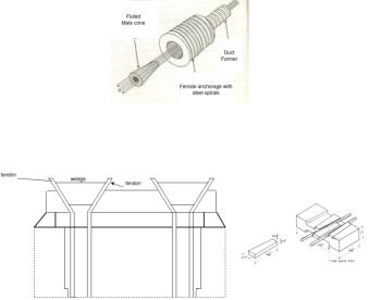
- 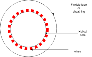 The entire assembly of the cable is placed in the prepared formwork of the member and tied in position. The anchorage fittings used in the system consists of two components i.e. i.)the female cone ii.)the male cone figure
- The female cones are threated over the cables at each end and fixed to the inside face of the end shuttering of the member.
- As concrete is poured in the formwork, the female cone is embedded in the concrete.
- Due to the corrugations on outer surface, they develop good bond with the concrete. The member is called. When the concrete has set and attend required strength, the tendons are tensioned by using free Freyssinet Jacking Unit.
- The jacking unit is kept at the tensioning end of the member and the cable wires are passed through the grooves and gripped by the wedges on the main piston.
- The pump of the jacking unit is operated to move the pistons and the wires are stretched.
- After stretching the wires of the desired limit, the male cone is put inside the female cone by operating the inner piston.
- This keeps the tensioned cable firmly in position. The jacking unit is removed for used in stretching the outer cables.
- Cement grout is then forced through the narrow pipe sleeve in the male cone to fill the annular space between the metallic tube and the cable completely.
- Finally the project in wire cut off and then anchorage is grouted to protect the steel from corrosion due to atmospheric actions.
Magnet-blaton system:-
- Cable ducts are formed in the body of the concrete member by extractable rubber cores. The prefabricated cables are then passed through the ducts.
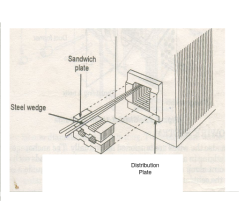
- Metallic special blocks are used to held the cables in the desired position. Cost steel distribution plates are cemented at each end off the precise member.
- The anchorage is done with steel plates known as sandwich plates with two trapezoidal grooves in the upper surface and two in the lower surface. Two wires can be placed in each groove.
- The wires are held in position by steel wedge which fits in the slot. In the sandwich plate which is illustrated in figure c, eight wires can be anchored and a cable may have several such plates.
- One pair of wire is tensioned at a time with the help of tensioning equipment. When the wires attention at the desired limit, the steel wedge is driven inside the groove which keep the two wires firmly in position.
Lee-Mccall System:-
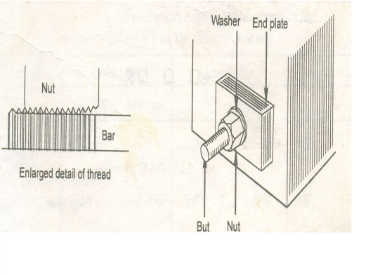
- A rod of high tensile alloy steel is used to act as a single tendon. The diameter of the bar varies between 12 mm to 28mm and it is threaded at both the ends.
- It is a common practice to insert the bar into the flexible rubber tube and suitably place and tie in position in the formwork of the member to be concreted.
- Concrete is poured into the formwork and after it has attained required strength, of the rubber tube is withdrawn.
- Perforated operated bearing plates with one hold for each rod, are provided at each end. At each end of the bar, one nut with washer is screwed.
- Jacking is done at only one end when the length of the members is small and hence the prestressing force required is also small.
- For long members requiring greater magnitude of prestressing force, one Jack is employed at each end of the bar. When the rod is stretch to the required length, the nuts are tightened.
Analysis of pre-stress:-
The analysis of prestress members i.e. rectangular and T-sections members can be different for the different staging of loading. The stages of loading are as follows:-
Stage of loading:-
a) Initial
b) Intermediate
c)Final
The precast members, has to be designed for three stages, the initial stage during prestressing, intermediate stage during handling and transportation and the final stage under external loading whereas for cost-in-sites structure prestressed concrete members are designed for at least two stages, initial stage during prestressing and the final stage under the external loadings.
a)Initial:-i) during tensioning of steel
Ii) at transfer of pre-stress to concrete
b) Intermediate:-This includes the loads during transportation of the prestressed
c) Final:-i) at service, during operation
Ii) at ultimate, during extreme events
ASSUMPTIONS IN THE DESIGN OF PRESTRESSED CONCRETE MEMBERS:-
i) A transverse plane section of the member will remain a plan after bending also.
Ii) With the limits of the deformations taxing place, Hooke’s law is applicable to concrete and steel components.
Iii) The stress in the reinforcement does not change along the length of the reinforcement breast changes take place for the concrete component only. Variation of stress in the reinforcement due to changes in the external loading is ignorable.
Iv) In case of bonded tendons, the bond between concrete and tendons is perfect and they act monolithically.
v) In prestressing stress in steel due to flexure caused by external loads is negligible compared to applied stress for prestressing.
Vi) The sectional properties are taken as that of gross sections of concrete, sends the cross sectional area of steel is very small as compared to that of concrete.
Analysis of prestress are analysed by stress concept
The stress due to prestressing alone are generally combined stresses due to the action of direct load and bending resulting from an eccentrically applied load.
The stresses in concrete are evaluated by using the well-known relationship for combined stresses used in the case of columns.
The analysis of prestressed by two method depends upon positions of tendon.
1) Concentric tendon
2) Eccentric Tendon
Analysis of pre-stress by concentric Tendon
A simply supported prestressed concentric beam of rectangular section prestressed by a tendon provided through its centroid longitudinal axis.
Let the beam be subjected to an external load system.

Let P be the prestressing forces supplied by the tendon. Due to this prestressing force, the compressive stress induced in concrete  where A is the sectional area of the member.
If due to the dead load and external loads, the bending moment at the section is m, then extreme stresses at the section due to bending moment alone.

Where, z is the section modulus of the beam section.
Hence, the final extreme stresses on the beam section are given by

Stress at the extreme top edge=
 And stress at the extreme bottom edge=
If the moment due to self weight is mg and that due to live loads  both being sagging, total stress in concrete is

i.e. stresses at bottom most and top most fibres of the section are


Remember, y is positive when it is above the neutral axis and it is negative when it is below the neutral axis.
Problem 01:- A pre-stress concrete beam 250mm wide and 375mm deep is prestress by concentrically placed tendon. The span of beam is 8m and beam has two sports and imposed load of 4.25 KN/M. Find the prestressing force necessary so that tension is just avoided at the soffit of the mid span
Solution:- given data
Width of beam b=250mm; depth of beam d=375mm, span=l=8m ; imposed load=w=4.25KN/M
 To find:- prestressing force P=?
1) Self weight of beam=25×0.375×0.250
=2.344KN/M
Total load=2.344+4.25=6.594 KN/M
2) Maximum bending moment= M=
3) Section modulus=
4) Prestressing force at the soffit of mid span


Problem 02:-A prestressed concrete beam 400×600mm in section has a span of 6m and is subjected to uniformly distributed load of 16KN/M including the self weight of the beam. The prestressing tendons which are located along the longitudinal centroidal axis provided an effective prestressing force of 960KN. Determine the extreme fibres stresses in concrete at the mid span section.
Given data:- b=400mm ; d=600mm ; L=6m ; 
1) Direct stress due to prestressing force 
2) Extreme stress due to bending moment
M=maximum bending moment M=
Z=section modulus=
 =M/Z =±
3) Finals faces in the extreme fibre will be as
Final stress in the extreme top fibres =
Final stress in the extreme bottom fibres =

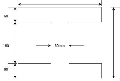
Problem 03:- A simply supported pre-stressed concrete beam of span 6m is of symmetrical I-section. The beam is 300mm deep each flange is 300mm ×60mm while the web is 60 mm thick. The overall depth of the beam is 300mm. It is provided with 60 wires of 2.50mm diameter equally distributed in the top and the bottom flanges. The beam has to support a superimposed load (in addition to its own weight) of 2 A moving paint load causes an additional bending moment of 5.60 KN.M
The beam has to support its own weight during the prestressing stage. Determine the stress distribution for the mid span section during transfer of prestress and after the action of other loads. Allow 15% loss at transfer and a further loss subsequently. The initial prestress in the wire is 1075 
Solution:-
1) Area of the beam section A
A=(2×300×60)+(180×60) = 46800
2) MI of the beam section

3) Section modulus 
4) Dead load of The beam=A×γ=

5) B.M. Due to dead load of The beam=
6) Area of 60 wires of 2.50mm diameter=
7) Initial prestress in the wires=1075
8) Allow 15% loss at transfer stress=0.85×1075=1075=913.75
Just after transfer
1) Compressive stress in concrete due to prestressing force


2) Extreme stress due to dead load of beam=
Hence, just after transfer
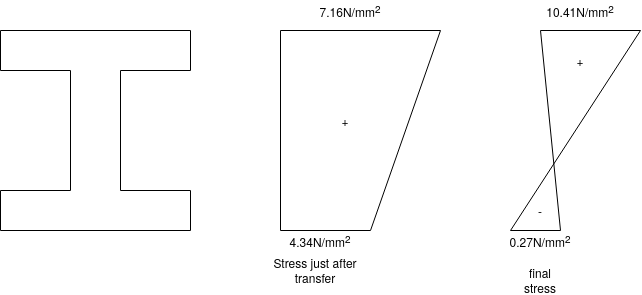
Stress at top=5.75+1.41=7.16 
Stress at bottom=5.75-1.41=4.34 
3) BM due to moving point load=5.60KNM
4) BM due to additional superimposed load=
5) Total BM=9+5.60+5.265=19.865KNM
6) Stress in the wires=0.75×1075=806.25
7) Compressive stress in concrete due to prestressing force

8) Extreme stress due to dead load of beam=±
9) Final stresses at top=5.07+5.34=10.41
10) Stresses at bottom=5.07-5.34=-0.27
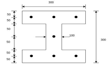
Problem 04:- An I section in concrete has the following dimensions flanges=(300×100)mm ; web=100mm×100mm. It is pre tensioned by 7 high tension steel wires of 8mm diameter. They are located as shown in figure. The wires are subjected to an initial stress of 1000 Find the stresses in concrete and steel immediately on cutting the wires, when the members is still supported in the prestressing bed. Assuming a loss of prestress of 200 N/
 including the loss of stress due to elastic shortening of concrete, calculate maximum moment so that tensile stress is avoided and the compressive stress does not exceed 12
 in concrete. Take m=6
Solution:- area of the section A=
Moment of inertia I=
 Section modulus
Area of steel wire 
Now, initial stress  =1000
=1000
Initial prestressing force 

Stresses immediately after cutting the wires
Stress in concrete  =
=
Loss of stress in steel due to elastic shorting of concrete

Stress in steel immediately after cutting the wires =1000-30.156
=
Subsequently the total loss of stress in the wires = 200
Final stress in steel. =1000-200 = 800 
Final prestressing force P = final stress in steel×area of steel wire
= 800×351.858
= 281.486
Direct stress=
To avoid the tensile stress, bending stress in the extreme fibres = ± 4.02
Let m = maximum permissible bending moment

=
=17.62KNM

Problem 05:- A Rectangular concrete beam of cross section 350 mm and 200 mm wide is pre-stressed by means of 15 wires of 5 mm diameter located at 6.5cm, 3 No.’s from the 5mm from the 2.5cm from the top. Assuming the prestress in the steel as 840  calculate the stresses at the extreme fibre of mid span section. When the beam is supporting its own weight over a span of 6m. If uniformly distributed live load of 6KN/M is imposed, evaluate the maximum working stress in concrete. The density of concrete is 24 KN/
Given data:- b=200mm d=350mm
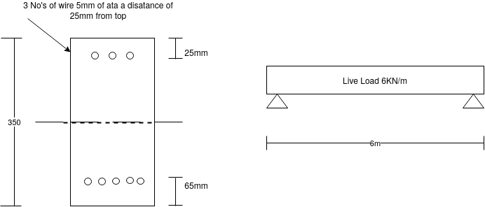
15 No.’s of wire 5mm  at a distance of 65 mm bottom a distance
1) Calculate distance of the centroid of prestressing force from base


Eccentricity 
2) Prestressing force P=prestressing× number of wire× area of one wire


3) Area of cross section A= bd = 200×350 =
4) Section modulus 
5) Moment calculation M =?
a) Due to self weight W = 24×0.2×0.35 =1.68KN/M

B) Due to live load w = 6KN/M

6) Stress calculation
a) Direct stress due to prestressing

b) Bending stress due to prestressing

c) Stress due to self weight

d) Stress due to live load

7) Resultant stress
a) At top 
b) At bottom 
Analysis of prestress by eccentric tendon
It will be advantageous to place the tendon at an eccentricity. Following figure shows a beam of rectangular section pre-stressed bi a tendon placed longitudinally, at an eccentricity 'e' from the centroidal longitudinal axis. Let The beam be subjected to an external load system. Let P be the prestressing force supplied by the tendon. Letter due to the dead load and external loads the bending moment at a section be m.

The stresses on the section consists of the following
1) Direct stress due to prestressing force = +P/A
2) Extreme stresses due to eccentricity of the prestressing force = ±
3) Extreme stresses due to bending moment = ±
Final stresses
a) Stress at the extreme top edge = 
b) Stress at the extreme bottom edge=

Problem No. 01:- A prestressed concrete beam 300 mm wide and 600 M deep is prestressed using 5 high tension bars of 12mm. Provide at 220 mm from the soffit of the beam. The effective stress in the steel is 800 Find the bending that must be applied to the section to just avoid tension at the soffit of the beam.
Given data:-
1) Area of beam A = 300×600 =180000
2) Area of steel =
3) Prestress force by wires = 800×565.48 = 452.38
4) Section modulus 
5) Eccentricity e = 300-220 = 80mm
Let m be the bending moment required so that the tension at the soffit in just avoided.
For this condition 


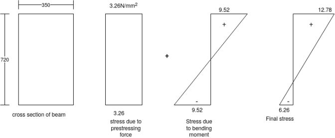
Problem No. 02:-A pre-stress concrete beam 350 mm wide and 700mm deep has a span of 11 m. The beam is subjected to UDL of 18 KN/M including self weight over entire span. A prestressing force of 800KN is applied along the centroidal axis determine the extreme fibres stress in the section.
Given data:- b=350mm; d=700mm; L=11m; UDL=w=18KN/M prestressing force P=800KN
To find:- final stress at top and bottom
Solution:-
1) Direct stress 
2) Extreme stress due to BM =
M = moment =
Z=section modulus

3) Final stress
a) Top =
b) Bottom =
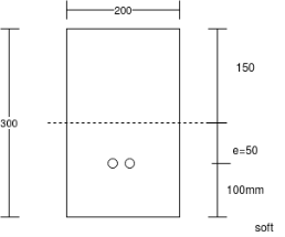
Problem No. 03:- Rectangular concrete beam of cross section 200mm×300mm having a length of 6m uniformly distributed load of 5KN/m acting on whole span. The density of concrete is is 24
1) Concrete prestressing force necessary for zero fibre stress at the soffit when the beam is fully loaded.
2) Eccentric prestressing force located 100 mm from the bottom of the beam which would nullity the bottom fibre stresses due to loading.
Given data:- b=200mm; d=300mm ; L=6m ; 
Solution:-
1) Section modulus 
2) Direct stress due to prestressing force 
3) Bending moment 
Due to dead load 
Due to live load 
Case-I when applied prestressing force is concentric


P = 580KN
Case-II When applied prestressing forces having an eccentricity 100mm from soffit i.e. (e=50mm)


Problem No. 04:- A prestressed concrete beam 400×600 mm in section has a span of 6m and is subjected to a uniformly distributed load of 16KN/m including the self weight of the beam. The prestressing tendons are located at the lower third point and provide an effective prestressing force of 960 KN. Determine the Extreme fibre stresses in concrete at the mid span section.

i) Section modulus z= 
Ii) Maximum bending moment due to external loading M
Iii) Direct stress due to prestressing force = 
Iv) Extreme stress due to eccentricity of the prestressing force =

v) Extreme stress due to external bending moment =
Vi) Final stresses for the extreme fibres will be as follows
At the top edge = 
At bottom edge

Problem No. 05:-A prestressed concrete beam 250 mm wide 375 mm deep is prestressed by concentrically placed tendon. The span of the beam is 8m and the beam has to support an imposed load of 42.5 KN/M. Find the prestressing force necessary so that the tension is just avoided at the soffit of the mid-section.
If, however, the tendon is provided at an eccentricity of 65 mm find the prestressing force necessary so that tension is just avoided at the soffit of the mid-section. Concrete weights 24
Given data:-
1) Area of beam A = b×d = 250×375 = 93750
2) Section modulus z = 
3) Load calculation
Dead load of beam = 0.25×0.375×24 = 2.25KN/M
Superimposed load on beam = 4.25KN/M
Total load = 6.50KN/M
4) Bending moment m
Let P be the prestressing force so that the tensile stress at the soffit of the mid section is just avoided.
Case 1 when the tendon is concentrically provided
For this case 

P=832KN
Case 2 when the tendon is provided at an eccentricity of 65mm
For this case


Problem No. 06 :-A rectangular concrete beam 100mm wide by 250 mm deep spanning over 8m is prestressed by a straight cable carrying and effective prestressing force of 250KN located at an eccentricity of 40mm. The beam support a live load of 1.2KN/m
1) Calculate the resultant stress distribution for the centre of span cross-section of the beam assuming the density of concrete as 24 
2) Find the magnitude of prestressing force with an eccentricity of 40mm which can balance the stresses due to dead and live load at the soffit of the centre span section.
Given data:- b=100mm; d=250mm; A = BD =100×250=25× span=L=8m ;
Prestressing force P = 250KN = ; eccentricity e =40mm
Live load on beam =
Solution:-
1) Section modulus z =
2) Maximum bending moment due to external loading =
Total load = (24×0.1×0.25)+1.2=0.6+1.2
=1.8KN/M

3) Extreme stress due to external bending moment =
4) Extreme stress due to eccentricity of the prestressing force =

5) Direct stress due to prestressing force = 
Case 1
6) Resultant stresses for the extreme fibres will be as
At top edge = 
At bottom edge =
Case-II if p=prestressing force required to balance the stresses at soffit, then
i.e. 


Problem No. 07:- A prestressed concrete beam of rectangular section 300 mm wide and 600 M deep has a span of 12m. The effective prestressing force is 980 KN add an eccentricity of 120mm. The dead load of the beam is 4.5KN/M and The beam has to carry a live load of 7.5KN/M. Determine the extreme stresses.
1) At the end section
2) At the mid section without the action of live load
3) At the mid section with the action of live load
Given data
1) Area of beam section A = 300×600=180
2) Section modulus of the section 
3) Bending moment 
Due to DL 
Due to LL 
1) At the end section
Direct stress due to prestressing force = 
Extreme stress due to eccentricity of the prestressing force =

Resultant stress at top edge = 5.45-6.53 = -1.08
At bottom edge = 5.45+6.53 = 11.98 (compressive)
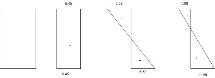
2) Analysis of the midsection subjected to prestressing force and dead load
1) Direct stress due to prestressing force =
2) Extreme stress due to eccentricity of the prestressing force = ±

3) Extreme stress due to dead load moment =
4) Resultant stress at top edge =
At bottom edge = 5.44+6.53-4.50 = 7.47

3) Analysis of the mid section subjected to prestressing force, dead load and live load
1) Direct stress = +5.44
2) Extreme stress due to eccentricity of the prestressing force = ±6.53
3) Extreme stress due to dead load moment =
4) Extreme stress due to live load moment
5) Resultant stress at top edge =
Resultant stress at bottom = 5.44+6.53-4.50-7.50= -0.03 (tensile)

Problem No. 08:- An unsymmetrical I section to support and imposed load of 1.8KN/M over a span of 7.8m top flange is 300mm wide and 60 mm thick bottom flange 100mm wide and 60 mm thick, web thickness is 80 mm with overall depth as 400mm. And effective prestressing force is 150 KN is there at 50 mm from soffit of beam at midspan what are the stress at the centre of span for
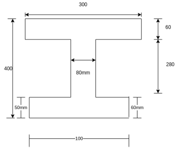 Pre-stress+self weight
1) Prestress + self weight + imposed load
[Amarvati-S-2014,2015,W-2014]
Given data:- imposed load=1.8KN/M
Span. L=7.8m, prestressing force=P=150KN
Area of total I-section A=
A= (300×60)+(100×60)+(80×280)
= 46400
Solution:-
1) Calculate C.G.
Y=distance of centroid from top


= 
2) Calculate eccentricity of prestressing force N.A.
Eccentricity (e) =(400-50)-y=350-156.04=193.96≈194mm
3) Calculate moment of inertia of section


4) Calculate section modulus (z)
 mm
mm


5) Calculate self weight of beam

6) Calculate moments
- Self weight of beam (

- Imposed load

7) Calculate stresses
Stress Type | Top Fibres | Bottom Fibres |
Direct stress |  |  |
Stress due to moment |  |  |
Stress due to self weight of beam |  |  |
Stress due to imposed load |  |  |
Prestress +self weight
At top=3.23-5.987+1.814 =- 0.943
At bottom=3.23+9.375-2.841=9.764
Pre-stress+self weight+imposed load
At top =3.23-5.987+1.814+2.82 = 1.877 
At bottom=3.23+9.375-2.841-4.410= 5.354
Problem No. 09:- A pre-stressed beam 500mm*750mm has a simple span of 8m and is loaded with a uniformly distributed load of 20KN/M including at 250mm from bottom face. The applied effective pre-stressing force is 2700 KN. Calculate the extreme fiber stresses in the concrete at the quarter span and mid-span section of beam. [AMIE-W-2017]
Given Data:-b=500mm;d=750mm: span L=8m UDL=W=20KN/M
Prestressing force P=2700KN
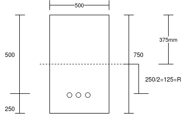 Eccentricity
To find:-final stress at top and bottom
Solution:-Area=b.d=500*750 =
Section modulus  =
=
Maximum bending moment m= 160KN.M
a) Direct stress due to prestressing force  = 7.2N/m
b) Extreme stress due to bending moment  =
=  3.41N/m
c) Extreme stress due to eccentricity of the Prestressing force =

d) Final stress for the extreme fibers will be as follows
i) Top stress = 
Ii) Bottom stress=
b) Extreme stress due to bending moment of quarter
L= = 2m
= 2m 
At the quarter of span=
At the center of span = But M=


Problem No. 10:-A prestressed concrete I-beam span 28m and carries a live load of 4 KN/M. Prestressing steel consists of 120 wires of 5mm diameter. Initial prestress is 1000  . Loss of prestress is 16%. Calculate the extreme fibre. Stress at mid span at transfer of prestress and at working load. [AMIE-S-2016]
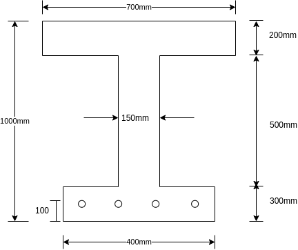
Solution:- The geometrical properties of the various components are given in the table below:
Component | Area (  | C.G. From top | a.y |  | I |
Top flange |  |  |  |  |  |
Web |  |  |  |  |  |
Bottom flange |  |  |  |  |  |
Total |  |
|  |  |  |


Moment of inertia about the axis


Dead load of the beam = Area*Density = 0.335*25=8.375KN/m
Eccentricity 
The extreme fibre stresses are calculated for the following cases.
Case-1 Beam subjected to initial prestressing force and dead load.
Initial prestressing force 

Dead load moment 
Direct stress 
a) Extreme stress due to eccentricity of the prestressing force
1) At top 
2) At bottom 
b) Extreme stress due to D.L. Moment
- At top

- At bottom

c) Final stress
- At top

- At bottom


Case-2 Beam subjected to final prestressing force, Dead/Live loads
Final prestressing force P=0.85
Live load moment 
Direct stress 
Extreme stress due to eccentricity of the prestressing force
3) At top 
4) At bottom 
Extreme stress due to D.L. Moment
3. At top 
4. At bottom 
Extreme stress due to LL moment
1) At top 
2) At bottom 
Final stress
3. At top = 
4. At bottom= 
Problem No. 11:- A prestressed concrete T-beam is to be designed to support an imposed load of 4.4KN/M over the span of 5m. The T-beam is made up of flange of size 400mm*40mm. The rib is 100mm wide and 200mm deep. If the allowable stress is limited to 15MPa and 0.75MPa in compression and tension, respectively determine the required prestressing force and its eccentricity at mid-span section.
AMIE-W-2015
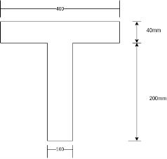 Given Data:- Live load
  : Span=L=5m Allowable stress
  &
&
To find:-
1) Prestressing force
2) Eccentricity
Solution:-
1) Area of section = (400*40)+(100*200)
=3600
2) Depth of the centroidal axis from the top edge


3) Moment of inertia about the centroidal axis 


4) Section modulus 

5) Dead load of the beam=0.036*25000=900N/M
6) Live load of the beam=4.4KN/M =4400N/M
Assume P=Initial prestressing force(N)
E=Eccentricity (mm)
Case-I :- When the beam is subjected to the initial prestressing force and dead load


Direct stress =
Extreme stress at top due to eccentricity of the prestressing force


Extreme stress at top due to DL moment

Extreme stress at bottom due to DL moment
=
For the condition of zero stress at top


The condition that the stress in the bottom to read, 15


Solve equation 1 & 2 we get,


- It has been observed that the prestressing force induced in a member does not remain constant but it decreases with the passage of time on account by various reasons.
- The total loss may be as high as 15 to 20% of the initial press tracing force.
- The designer must take into account all such losses. The important causes of loss in prestressing force are the following.
1) Due to elastic shortening of concrete
2) Due to creep in concrete
3) Due to Shrinkage of concrete
4) Frictional loss
5) Due to creep in steel
6) Due to slip at anchorages.
Losses in pre-stress concrete
Cause | Post tensioned member | Pre tensioned member |
Shrinkage of concrete | 6% | 7% |
Creep of concrete | 5% | 6% |
Creep in steel | 3% | 2% |
Elastic shortening and bending of concrete | 1% | 3% |
Total | 15% | 18% |
No. Pre tensioning | No. Post tensioning |
Elastic deformation of concrete | No loss due to elastic deformation if all the wires are simultaneously tensioned. If the wires are successively tensioned, there will be loss of prestress due to elastic deformation of concrete |
Relaxation of stress in steel | Relaxation of stress in steel |
Shrinkage of concrete | Shrinkage of concrete |
Creep of concrete | Creep of concrete |
| Friction |
| Anchorage slip |
- 1)Loss due to elastic shortening of concrete
a) For pre tensioned members: - Due to the prestress transferred to the concrete, the concrete will shorten. This results in a corresponding shortening of the steel. The prestress in the steel is automatically reduced as it is allowed to shorten slightly.
Let the intensity of the compressive stress in concrete be 
Let the Young's modulus for concrete be 
Strain in concrete  but.
but. 
If  is the area of concrete and P beat the prestressing force
We have  =>
=>
Since the steel will also shorten as the concrete shortens,
The loss of strain in steel=strain in concrete =
Loss of prestress  = Young's modulus for steel
 where
where  modular ratio=
In the above expression P the prestress prevailing finally may not be known. But for a sufficiently correct estimation of the loss of prestress it is enough if the initially applied prestress P is adopted.
- Strain in concrete at the level of steel =
- Stress in steel corresponding to this strain =(
Modular ratio m =
- Loss of stress in steel =
- if the initial stress in steel is known the percentage loss of stress in steel due to the elastic deformation of concrete can be computed.
b) For post tensioned members
- When more than one tendon is provided the various tendons are not simultaneously tensioned. There will be tensioned in succession.
- Consider one tendon is tensioned. Due to this, elastic shortening takes place. When elastic shortening of concrete takes place elastic shortening of second tendon causes loss of prestress in first tendon.
- Similarly after tightening of third tendon, first two tendons suffer loss of prestress. The average loss is half the loss of prestress experience by 1st tendon.
Problem:- Determine the loss of prestress due to elastic shortening in concrete beam of size 150 mm wide and 250 m deep which is prestressed with 6 wires of 7mm diameter, located at 75 mm from soffit, take initial prestress=1200
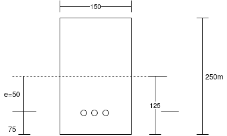 Given data:- b=150mm; D=250mm ;
Soffit=75mm; eccentricity=125-75=50mm
Initial prestress 
Solution:- to find the loss of prestress due to elastic shortening
1) Area of beam=A=bd=150×250=
2) Second moment of inertia 

3) Prestressing force applied at tendon=F=A. = 230.91×1200 = 277.092×

4) Stress in concrete at the level of steel 


=7.389+3.55

5) Loss of stress due to elastic deformation=  =6×10.94=65.64
6) Percentage loss of stress in steel=
Problem no 02:- A pretensioned concrete beam of rectangular cross section, 150mm wide & 300mm deep, is a prestressed by eight high tensile wires of 7 mm diameter located at 100 mm from the soffit of the beam. If the wires are tension to a stress of 1100  , calculate the percentage loss of stress due to elastic deformation assuming the modulus of elasticity of concrete and steel as 31.5 and 210
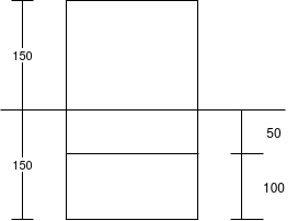 Solution:- b=150mm ; d=300mm;
Eccentricity=150-100=50mm
Tension stress 
Modulus of elasticity of concrete 
Modulus of elasticity of steel 
Solution:- 1) prestressing force 
=1100×308

=338.8KN
2) area of section A=bd=150×300=
3) Second moment of inertia M

4) Modular ratio m=
5) Stress in concrete at the level of steel


6) Loss of stress due to elastic deformation = 
= 6.67×10.03 = 66.90
7) Percentage loss of stress in steel =
=6.08%
Problem no 03:- The figure shows the cross section of a pretensioned beam of span 6m, simply supported at an ends and carrying uniformly distributed load of 8KN/m over entire span. Determine the loss of prestress due to elastic the formation under the combined effect of prestressing force and external moment. Given No.’s of 7mm prestressing straight wires =3
Initial prestress in steel=1100 ; modular ratio=7
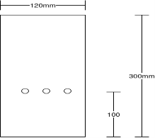 Given data:- b=120mm; D=300mm ;
To find:- loss of prestress due to elastic deformation
Solution:-
1) Area of beam=A=b.d =120×300 = 36000
2) Moment of inertia 

3) Pre-stress force at tendon =115.45×1100 =126.99×
4) Eccentricity 
5) Bending moment due to external load 
This moment where is parabolically along the length of the beam with zero value add supports and 36KNM at midspan
∴ Average moment=
6) Hence average stress in concrete at the level of steel (y=50mm)

7) Increase in stress in steel wires = m×
8) Compressive stress in concrete at the level of steel due to prestressing force


=3.53+1.175
=4.705 
9) Loss of stress in steel =
10) Due to combined effect of prestressing force and external movement loss of prestress

Problem no 04:- A rectangular concrete beam 300 mm deep and 200 mm wide, is a prestressed by means of 15mm diameter wires located 65 mm from the bottom of the beam and 3mm wire, located 25mm from the top of the beam. If the wires are initially tension to a stress of 840  calculate the percentage loss of stress in steel immediately after transfer allowing for the loss of stress due to elastic deformation of concrete only.
Given data:- b=200mm ; d=300mm 
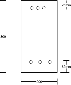 Assume modulus of elasticity of concrete
Assume modulus of elasticity of steel 
Solution:-
Area of concrete A=300×200=60000
Position of the centroid of the wires from the soffit of the beam

Eccentricity e=150-100=50mm
Second moment of area 

σ=P/A=
Initial prestressing force P=296.88KN
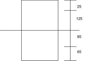 Stress in concrete
a) At the level of top wires =

= 4.948 - 4.12
=0.828 
b) At the level of bottom wears =


Modular ratio =
1) Loss of stress in wires at top = 
=6.67×0.828
2) Loss of stress in wires at bottom = 
=6.67×7.758 =51.75
Percentage of loss of stress
1) For wires at top =
2) For wires at bottom =
Problem no 05:- The given figure shows the cross section of a pretensioned beam of size 200mm×400mm, which was prestressed with 15 straight wires of 5 mm diameter located in three layers. Determine the average loss of prestressing force due to elastic shortening, if initial stress was 1200  Take modular ratio m=
  = 7
= 7
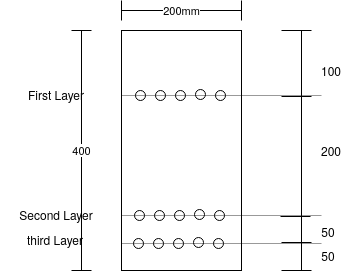
Solution:-
1) Area of beam= A=b.d=200×400=80×
2) Moment of inertia 

3) Total prestressing force 
=353.42KN
4) Prestressing force at each level

5) Centre of gravity of prestressing force from top edge

6) Eccentricity of prestressing force e = 250 - 
7) Distances of every layer from N.A.
First layer 
Second layer 
Third layer 
8) Compressive stress at the level of first layer


9) Loss of prestress in first layer =
10) Compressive stress at the level of second level


11) Loss of prestress in second layer
12) Compressive stress at the level of third level


13) Loss of prestress in third layer
14) Average loss of prestress due to elastic shortening


Loss due to creep in concrete
- Creep is deformation of concrete depending upon the time interval to which the member is loaded.
- A concrete member undergoes deformation due to external loading. If now this member is loaded for a long time, It is seen that the deformation increases.
- The additional deformation due to long time interval loading is called creep. If
 is the instantaneous strain immediately after loading the
  is the strain after long time then the ratio
  is called the coefficient of creep.
- Value of coefficient of creep varies considerably up to two years period and then there is no appreciable change.
 is then taken as 2.5 to 3. Lower value is for post tensioned members and higher value for pre tensioned members.
Loss of stress due to creep will be. 
Where;  =creep coefficient
 =original stress in concrete
m=modular ratio
Loss due to shrinkage and creep can be combined as:

Where  shrinkage strain
Creep coefficient method
Creep coefficient=c=

Hence, loss of stress =
The Indian and British quotes recommend the values of 70 creep coefficient for varying humidity age at loading and the notional size of the member. The value of the creep coefficient varies from a minimum of 1.0 to maximum of 5.8
For grades of concrete from M-30 to M-60 generally used in prestressed members, the values of creep coefficient listed in the table below are useful in computing the loss of stress due to creep in concrete.
Where;  =creep coefficient ;
  creep strain
  elastic strain
m= modular ratio ;  stress in concrete
  modulus of elasticity of steel
  =modulus elasticity of concrete.
Where
t=age of concrete in days at the moment considered.
 age of concrete at loading in days,
 duration of loading in days
 =A coefficient depending on the relative humidity( RH in percent) and the notional member size
  .
.


RH=relative humidity expressed as percent
 100(that is, 100 percent relative humidity)
 = coefficients to consider the influence of the concrete strength,

t=age of the concrete at the moment considered in days,
 =age of the concrete at the beginning of drying shrinkage, in days; normally this is at the end of curing; and
 =notional size of the cross section, in mm=
 where
where  is the concrete cross-sectional area and use the parameter of that part of the cross-section which is exposed to drying.
6.2.5 Creep
Creep of concrete depends, in addition to the factors listed in 6.2.4 on the stress in the concrete, age at loading and the duration of loading. As long as the stress in concrete does not exceed one third of characteristic compressive strength, creep may be assumed to be proportional to the stress.
6.2.5.1 The creep coefficient.
Where
 =Creep strain at time
 =Initial strain at loading, and
 =initial time of loading
The creep coefficient  is given by:

Where
 =Notional creep coeffcient to which the creep coefficient reaches asymptotically with time (this can be taken as value reached in 70 years), and
 = Coefficient describing development of creep with time ( see 6.2.5.2)
The notional creep coefficient  is given by

Where
 =a factor to allow for the effect of relative humidity on the notional creep coefficient.


(RH=relative humidity of the ambient environment in percent,
 notional size of the member, in mm=
 =cross sectional area, and
 =perimeter of the member in contact with the atmosphere.
 =A factor to allow for the effect of concrete strength on the notional creep coefficient

 =a factor to allow for the effect of concrete age at loading on the notional creep coefficient

Where end read results are not sensitive precise values calculated as given above, the values given in table below can be considered as final creep coefficient for design for normal weight concrete of grades between M 30 and M 60 subject to condition that the compressive stress does not exceed  at the age of loading, and mean temperature of concrete is between 10°C and 20°C with seasonal variation between -20°C and 40°C. For temperature greater than 40°C the coefficient given may be increased by 10%. In the absence of accurate data.
Age at loading Creep coefficient  of an ordinary structural concrete after 70 years of
 loading
Under Dry Atmospheric Under humid Atmospheric Conditions (RH 50%) Conditions (Outdoor ) (RH 80%)
Notional Size( Notional Size (
| 50mm | 150mm | 600mm | 50mm | 150mm | 600mm |
(1) | (2) | (3) | (4) | (5) | (6) | (7) |
1 | 5.8 | 4.8 | 3.9 | 3.8 | 3.4 | 3.0 |
7 | 4.1 | 3.3 | 2.7 | 2.7 | 2.4 | 2.1 |
28 | 3.1 | 2.6 | 2.1 | 2.0 | 1.8 | 1.6 |
90 | 2.5 | 2.1 | 1.7 | 1.6 | 1.5 | 1.3 |
365 | 1.9 | 1.6 | 1.3 | 1.2 | 1.1 | 1.0 |
6.2.5.2 the development of creep with the time may be taken as 

Problem No 01:- A concrete beam having a width of 100 mm and depth 300mm is post tensioned by a parabolic cable with an eccentricity of 50 mm at the centre of span and concentric at the supports. Assuming an ultimate creep coefficient of 3.0 Estimate the loss of stress in the cable due to creep of concrete. [Force in cable P=240KN] 
Given data:- b=100mm ,d=300mm ,e=50mm ; creep coefficient  =3.0
=3.0
Solution:-
1) area of concrete A =100×300=
2) Force in cable P=240KN=240×
3) MI=
4) Modular ratio 

5) stress in concrete at the level of cable at support and centre of span sections are computed as
a) At support section =
b) At centre of span section =

Average stress at the level of cable  =
=
Loss of stress =  = 3×9.335×5.42 =151.78
Problem No 02:-A concrete beam of rectangular section 100mm wide and 300 M deep is prestressed by five wires of 7 mm diameter located at an eccentricity of 50mm, the initial stress in the wires being 1200  .estimate the final loss of stress in steel due to creep of concrete according to the IS-1343-2012 (
 )
)
Given data:- b=1000mm ; d=300mm  ; eccentricity e=50mm
Solution:-
1) area of concrete =b.d =100×300=30
2) Second moment of area I = 
3) Assume modulus of elasticity of concrete 

Modulus of elasticity of steel =
4) Modular ratio 

5) Initial prestressing force in wire 
Assume humidity=50%, age at loading=28 days
6) Stress in concrete at the level of steel is given by


7) Loss of stress =
Assuming that the sides and bottom width of the beam is exposed to the environment:- notional size 
Use table, read out the value of creep coefficient corresponding to the values of relative humidity 50%, age at loading as 28 days and notional size 85.71mm

Loss of stress=  =2.8×10.26×5.42=155.70
Problem No 03:-A Post tensioned PC beam of rectangular section 150 mm wide and 350 M deep is stressed by a parabolic cable concentric at the supports and an eccentricity 55mm at the centre of span. The area of high tensile steel in cable is 220  and initial stress in the cable is 1100
 . If the ultimate creep strain is
  of stress and modulus of elasticity of steel is 210
  Compute the average loss of stress in steel due to creep of concrete.
Given data:- width of beam=b=150mm ; depth of beam=d=350mm
Eccentricity e=55mm at centre of span and zero at supports.
Cable stress P=(220×1100)=242×
Ultimate creep strain =  =
= modulus of elasticity
Calculate average loss of stress in steel due to creep of concrete
Solution:-
Area of beam A = bd =150×350 = 52500
Moment of inertia I =
Stress at support  =
= 
Stress at centre of span section


Average stress at the level of steel

Loss of stress in the cable due to creep of concrete is


= 
Problem No 04-:- Figure shows the cross section of a pretensioned prestress T-beam, built in a dry atmospheric condition. The beam is a prestressed with 7000KN force the centroid of wires being at 150 mm from the soffit. Determine the loss of pre-stress due to creep, if modular ratio is 6 and age of concrete at loading is 28 days.
Given data:- prestress force P=7000KN; m=6, age of concrete at loading=28 days
Solution:-
1) Area of section = (1200×200)+(300×1200) = 600
2) 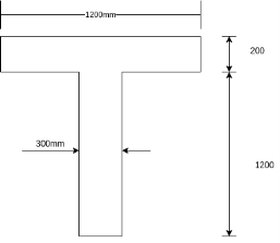 Distance of N.A. From top fibre


=520mm
3) Eccentricity e = y =1400 - 200-520 = 680mm
4) Moment of inertia 


5) Stress in concrete


6) Calculate notional size of the member
 [IS-1343-2012; Cl. No. 6.2.5.1 PP-6]
Where 
u= perimeter of section = (2×1200)+(200+1200)×2
=2400+2800
=5200

Now, as per IS-1343-2012; Clause No. 6.2.5.1 PP-6 from table calculate  by interpellation for 28 days
150 | 2.6 |
230.76 | X |
600 | 2.1 |

=2.51

We know,
Loss of stress in steel =
=2.51×39.91×6
=601.04 
Problem No 04-:- Determine the loss of prestress due to creep, if the beam referred previous example in post tensioned. Given that age of transfer is 12 days after the end of curing for 28 days and 
Given data:- 
Solution:- we know that,
Loss of prestress due to creep= 
As per IS-1343-2012; Clause No. 6.2.5.2 PP-6
The development of creep with time may be taken as 
 ------------------(1)
Where ; t=age of concrete in days at the moment considered
 age of concrete at loading in a days
Now,  = duration of loading in days
 =Coefficient depending on the relative humidity and the notional member size(
 )
)

 relative humidity expressed as percent=50(given)
 100 (that is, 100 percent relative humidity)=100
 230.76mm (previous problem)


1=>
We know 
Where;

 [Calculate previous problem]

Creep coefficient after post tensioning 

=1.74
Loss of prestress due to creep =
Where
M=modular ratio=6
 stress in concrete = 39.91
  (calculate previous example)
 =creep coefficient =1.74
(2) => =6×39.91×1.74
=416.66 
Loss of prestress due to shrinkage of concrete [IS 1343-2012, clause no. 6.2.4 PP-5]
- Shrinkage of concrete occurs due to chemical changes and drying. This depends upon the interval of time and moisture conditions, but this is independent of the stresses due to loads.
- Shrinkage is in proportion with water content in concrete. Hence by minimising the water cement ratio this shrinkage can be reduced by using well graded and large size aggregates also this loss can be reduced.
- Shrinkage strain is in between 0.0002 to 0.0004
Loss of stress = shrinkage strain×

Generally moist curing is restored to in order to prevent shrinkage until the time of transfer. Consequently the total residual shrinkage strain will be larger in three tensioned members after transfer to prestress in comparison with post tensioned members, where a portion of shrinkage will have already taken place by the time of transfer of stress.
Total shrinkage strain ( comprises of two components, the drying shrinkage strain (
 and the autogenous shrinkage strain (
  Expressed as

Loss of stress=
Where  modulus of elasticity of steel
6.2.4 shrinkage
The total shrinkage of concrete depends upon the constituents of concrete, size of the member and environmental conditions. For a given humidity and temperature, the total shrinkage of concrete is most influenced by the total amount of water present in the concrete at the time of mixing and, to a lesser extent, by the cement content.
6.2.4.1 the total shrinkage strain is composed of two components, the autogenous shrinkage strain and the drying shrinkage strain.
The value of the total shrinkage strain, is given by:

Where
 =Total shrinkage strain;
 =Drying shrinkage strain; and
 = Autogenous shrinkage strain
6.2.4.2 The autogenous shrinkage strain develops during hardening of concrete; the major part develops in the early days after casting. Autogenous shrinkage is a linear function of concrete strength. It should be considered specifically when new concrete is cast against hardened concrete.
In the absence of accurate field/laboratory data, the following values may be considered in design:
Grade of concrete | Autogenous shrinkage  |
M 30 | 35 |
M 35 | 45 |
M 45 | 65 |
M 50 | 75 |
M 60 | 95 |
6.2.4.3 the drying shrinkage strain develops slowly, as-it-is function of migration of the water through the hardened concrete.
The final value of the drying shrinkage strain,  may be taken equal to
 values of
  may be taken from the table given below for guidance. These values are expected mean values, with a coefficient of variation of about 30%.
 Unrestrained Drying Shrinkage Values
  for concrete with Portland
 Cement, for Relative Humidity
| 50 percent | 80 percent |
(1) | (2) | (3) |
25 | 535 | 300 |
50 | 420 | 240 |
75 | 330 | 190 |
Note-The values for the other designated grades may be obtained by interpolation
 is 1 or fission depending on the notional size
  as given below:
 Mm |  |
100 | 1.0 |
200 | 0.85 |
300 | 0.75 |
 | 0.70 |
6.2.4.4 The development of autogenous shrinkage with time may be taken as:

Where
 where t is in days.
6.2.4.5 the development of the drying shrinkage strain in time may be taken as


Where
t=age of the concrete at the moment considered, in days;
 age of the concrete at the beginning of drying shrinkage, in days; normally this is at the end of curing; and
 =notional size of the cross section, in mm =
 where
where  is the concrete cross-sectional area and use the perimeter of that part of the cross-section which is exposed to drying.
Problem No 01:- calculate the percentage of prestress due to shrinkage when tendon is subjected to initial prestress 1050  and shrinkage strain is 0.0003.[ AMIE-W-2016]
Given data:-
Shrinkage strain 
Initial prestress  =1050
=1050 
Solution:-
We know
=
=
=60
Percentage of prestress due to shrinkage = 
= 5.71%
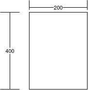
Problem No 02:- calculate the percentage loss of prestress in the cables of a pretensioned beam of size 200mm×400mm due to shrinkage of concrete. Take the relative humidity of the region as 50 percent,  relative humidity=50% ;
  initial prestress
To find:- percentage loss of pre-stress in the cables.
Solution:- As per IS-1343-2012; clause number 6.2.4 PP-5
Total shrinkage strain 
Where,
 =Total shrinkage strain
 =Drying shrinkage strain
 = Autogenous shrinkage strain
 = Autogenous shrinkage depends upon grade of concrete
M-50 =>
 = During shrinkage strain =
 =
= …..[IS-1343-2012- Clause No. 6.2.43 PP-05]
 Now,
Now,
 is a coefficient depending on the notional size
Now, 
Where,  =area of concrete = 200×400 =
= The perimeter of that part of c/s which is exposed to drying
=(2×200)+(2×400)=1200mm

 |  |
100 | 1.0 |
133.33 | x |
200 | 0.85 |


Total shrinkage strain 


We know, loss of prestress in The beam =


Percentage loss of prestress due to shrinkage of concrete


Problem No 03:- Determine the percentage loss of pre-stress due to shrinkage in the beam if the beam size 200 mm ×400mm is a post tensioned beam. Take the relative humidity of the region as 50 percent,  grade of concrete M-50, initial prestress =
 age of transfer in 12 days after the end of curing for 28 days.
Given data:- size of beam b=200mm ; d=400mm post tensioned beam; relative humidity=50% ;  ;age of transfer is 12 days after the end of curing for 28 days.
Solution:- we know; loss of prestress in the beam= –---------------(I)
Where 
 =Drying shrinkage after post tensioning
= Final drying shrinkage - drying shrinkage at the time of post tensioning –------(II)
Final drying shrinkage = 
 is the coefficient depending on the notional size

 |  |
100 | 1.0 |
133.34 | x |
200 | 0.85 |


And  =drying shrinkage strain
= [IS-1343-2012; Clause No. 6.2.4.3 PP-5]
Final drying shrinkage=
Drying shrinkage at the time of post tensioning

Where, 
Where,


(3) => 

(2)=>
= 
(1) => Loss of prestress in the beam = 


Percentage loss = 
= 
Problem No 04:-A concrete beam is the prestressed by a cable with an initial stress of 1000  in the wires. The grade of concrete in the beam is M-50 . The beam is located in an area having a relative humidity of 50%. The beam is exposed to the environment on three sides having a depth of 400mm and a width of 300mm. The beam was cured for 7 days before it was prestressed using the IS code method, estimate the loss of stress in steel due to shrinkage of concrete at the age of a) 28 days b) 70 years
Assume modulus of elasticity of steel as 210 
Given data:- Initial stress in wires 
 relative humidity= 50% : d=400mm ; b=300 mm
Case-I loss of stress due to shrinkage at 28 days
1) At 28 days, the autogenous shrinkage strain [ 6.2.4.4 PP-5]

Where,
 where t is in days
=
=0.6529
From Clause no. 6.2.4.2 PP-5 use table, corresponding to M-50 grade concrete, read the value of 
(1) =>

Ii) The drying shrinkage strain at 28 days is computed as using 6.2.4.5 PP-5

Where,

In this expression, t=28 days & hence (


The value of  corresponding to a value of
So, 
For M-50 grade concrete at a relative humidity of 50% read the value of unrestrained drying shrinkage from table 6.2.4.3 pp-5

(2) =>

2) Total shrinkage strain is computed as =


3) Loss of stress in steel due to shrinkage of concrete

=
4) % loss of stress=
Case-II loss of stress in steel due to shrinkage at 70 years
The long-term shrinkage strain comprises of both the autogenous and drying shrinkage strains.
For M-50 grade concrete, read the value of autogenous shrinkage strain
 [6.2.4.2 pp-5]
1) At 70×365=2550 days, the autogenous shrinkage strain

Where,  where t is in days
=
=1
(1)=>
2) The drying shrinkage strain at 70 years is computed as using 6.2.4.5 PP-5

Where;

In this expression, t = 25550 days and 


(2)=>
3) Total shrinkage strain is computed as 
=

4) Loss of stress in steel due to shrinkage of concrete =
=

5) % of loss of stress =
Frictional loss:-
- The prestressing force reduces beyond the tensioning and due to the friction between tendons and surrounding can create or any flexure attached to the steel or concrete.
- This reduction in prestressing force is known as loss of prestress due to friction.
Loss of prestress due to friction [IS-1343-2012, 19.5.2.6 PP-25]

 prestressing force in the the pre-stressed steel at the tensioning and acting in the direction of the tangent to the force of the cable.
 =Coefficient of friction in curve
 =Cumulative angle in radians through which the tangent to the cable profile has turned between any two points under consideration.
K=coefficient for wave effect
x= distance metres from free and wherever loss of stress is to be found.
Jacking from one end, maximum loss at x=1
Jacking from both ends, maximum loss at x=1/2
Problem no 01:- determine the stress required at the jacking end of a cable in the cylindrical wall of a water tank show that at the dead end stress is 1200  . Given the cable subtends an angle of 60° and wires cables are taken through bright metal duct. Ignore wave effect.
Given data:- prestressing force 
Angle α =60° = radians
To find 
Solution:-
For wire cables through bright metal ducts, as per IS-1343-2012, clause number 19.5.2.6 PP-25.
 =0.25. And K=0.0091/m
We know relation


Problem no 02:- A post tensioned beam of 8m span is tensioned with 3 galvanized wire cables, the area of each cable being 150 and initially stressed to 1200
  Determine the percentage loss of stress due to friction if,
a) The cables are straight
b) The cables are parabolic with zero is eccentricity at the ends and 100mm below the centroid at midspan.
c) The shape of the cable is circular with same eccentricity as in cable (b)
Assume that stressing was only from one end
Given data:- span = L = 8m; 3 galvanized wire cables area =
Initial stress 
Solution:- Case-I :- if the cables are straight

For wire cable through galvanised ducts, as per IS-1343-2012, clause no. 19.5.2.6 PP-25
 =20. And K=0.0046 /m
In this case cable are straight i.e.
 L=x=8m
We know 


Loss of pre-stress =


Percentage loss of prestress = 0.036×100 =3.6%
Case-II if cables are parabolic [eccentricity zero at ends and hundred mm below the centroid at midspan.
We know that, equation of a parabola is given by

∴Slope at any point at a distance x from end is

But slope at end i.e. X=0

At mid span, where x=l/2 is=0
∴ Change of slope from end to mid span section=0.05 radians
∴ Cumulative angle change between the two ends = 2×0.05 = 0.1 radians
We know that, 
Where, K=0.0046/m; u=0.20  and L=8


Loss of prestress =

∴Percentage loss of prestress = 0.0552×100 = 5.52%
Case-III if the cable shape is circular:-
The radius R of the curved profile can be found as


Angle

Total change in angle = 2×0.05 = 0.1 radians
We know 
Where


Loss of prestress =


∴ Percentage loss of prestress = 0.0552×100
=5.52
Problem no 03:- A concrete beam of 10m span, 100 mm wide and 300mm deep is prestressed by three cables. The area of each cable is 200 and the initial stress in the cable is 1200
  . Cable one is parabolic with an eccentricity of 50 mm above the centroid at the supports and 50 mm below at the centre of span. Cable 2 is also parabolic with zero eccentricity at supports and 50 mm below the centroid at the centre of span. Cable 3 is straight with uniform eccentricity of 50 mm below the centroid. If the cables are mentioned from one end only, estimate the percentage loss of stress in each cable due to friction. Assume
  =0.35 & K=0.0015 per m.
Given data:- span = L =10m ; b =100mm ; d=300mm ; area of of each cable =
Initial stress 
Solution:- Equation of a parabola is given by

Slope at ends(at x=0) =  =
= 
1) For cable no.1 i.e. e =50+50=100. L=10m =1000mm
Slope at ends= radians
∴ Cumulative angle between tangents  = (2×0.04)=0.08 radians
Loss of stress due to friction =
=


% of loss of stress=
2) For cable No. 2
Slope at end=
∴Cumulative angle between tangents 
Loss of stress due to friction=


% Loss of stress =
=
3) For cable No.:-03
Slope at end=0
Loss of stress due to friction=

=1200(0.015)

% loss of stress =
=1.5%
Problem no 04 :- A post tensioned concrete beam, 200mm wide and 450mm deep is prestressed by a circular cable(total area=800 ) with zero eccentricity at the ends and 150mm at the centre. The span of the beam is 10m. The cable is to be stressed from one end such that an initial stress of 840
 is available in the unjacked end immediately after anchoring. Determine the stress in the wires at the jacking end and the percentage loss of stress due to friction.
Given Data:- b=200mm;d=450mm ; Area of circular cable = 800
Eccentricity at zero end and 150mm at the centre; Span=L=10m; Initial stress 
To find:- Percentage loss of stress due to friction
Solution:- If the cable shape is circular, the radius R of the curved profile can be found as


R=83.41 
If  angle between the horizontal and the tangent drawn to the cable at support then


∴Cumulative angle between tangents to the cable at supports

We know

Where:


∴Loss of stress in cable=
∴Percentage of loss of prestress =

Problem no 05:-A cylindrical concrete tank, 40m external diameter is to be prestressed circumferentially by means of a high-strength steel wire ( ) jacked at four points. 90 degrees apart. If the minimum stress in the wires immediately after tensioning is to be 600
  and the coefficient of friction is 0.5. Calculate;
a) The maximum stress to be applied to the wires at the jack and
b) The expected extension at the jack.
The prestressing force at the farther end ,  is related to the force at the jacking end,
  by the expression.
Solution:- D=40m  ,
, 
We know  [clause no-19.5.2.6, PP-25]


∴Average stress in wire = 
Length of wires=

Extension at the jack =
=143.28mm
=144mm
Loss due to creep in steel
- The loss of prestress due to creep of steel is the product of modulus of elasticity of steel  and creep strain of steel
- It varies from 2 to 8% of the average initial prestress depending upon quality of steel and order of initial stress.
Loss due to slip in anchorages
- This loss is due to the fact that the anchoring fixtures are themselves subjected to a stretch. It is also possible that the wedges holding the wires may slip.
- The amount of slip may be taken as average 2.5mm to 0.75mm loss of prestress due to deformation of anchorage

 =Deformation of anchorage
 =Young’s Modulus for tendon
L=Length of tendon
The loss during anchoring, which occurs with wedge-type grips, is normally allowed for on the site by over-extending the tendon in the prestressing operation by the amount of the draw in before anchoring. However, this method is satisfactory provided the momentary over stress does not exceed the prescribed limits of 80-85% of the ultimate tensile strength of the wire.
The magnitude of the loss of stress due to the slip in anchorage is computed as follows:

 =Slip of anchorage, mm
L=Length of the cable, mm
P=Prestressing force in the cable, N
A= C/S area of the cable, 
 =Modulus of elasticity of steel,
Loss of stress due to anchorage slip =
Problem no 01:- A concrete beam is post-tensioned by a cable carrying an initial stress of 1000  . The slip at the jacking end was observed to be 5mm. The modulus of elasticity of steel is 210
  . Estimate the percentage loss of stress due to anchorage slip if the length of the beam is
a) 30m
b) 3m
Solution:- Initial stress  ;
; 
Loss of stress due to anchorage slip = 
a) For a 30m long beam, loss of stress =
∴% of loss stress=
b) For a 3m long beam, loss of stress =
∴% of loss stress=
Problem no 02:-Determine the loss of prestress due to slip of 5 mm in anchorages in a beam
a) beam of length=25m
b) Sleeper of length =2.70m
Take 
Solution:- Case-a) In a beam of length 25m
Loss of strain =
∴Loss of stress =

Case-b) Loss in a sleeper of length 2.75m
Loss of strain=
∴Loss of stress=

Problem no 03:-A prestressed concrete girder of 25m span is prestressed by a parabolic cable concentric at supports and having an eccentricity of 800mm at centre of span. The effective stress in tendons is 1100  The coefficient of friction between tendons and cable duct is 0.5 and the friction coefficient for wave effect is 0.0015/m. If the anchorages slip is 5mm, compute the loss of stress in tendons due to friction and anchorage slip. Assume
Given data:- Span = L = 25m; Eccentricity at centre of span = e = 800mm
Initial stress  ; Coefficient of friction
  ; K=0.0015/m ;Anchorage slip
  ;
; 
Solution:- Total change of slope=
∴Loss of stress due to friction=

∴Loss of stress due to anchorage slip=
Total loss of stress in tendons due to friction and anchorage slip
=182.05+42
=224.05
∴Percentage loss of stress=
Problem no 04:-A prestressed concrete girder of 30m span is prestressed by a parabolic cable concentric at supports and having an eccentricity of 900mm at centre of span. The stress in the wires is 1100  , ultimate shrinkage strain=0.0002,
  , coefficient of friction=0.5, anchorage slip=8mm, Estimate the percentage loss of stress in the wires.
Given Data:- Span = L = 30m; Eccentricity at centre of span = e = 900mm
Initial stress  ; Coefficient of friction
  ; Anchorage slip
  ;
;  Ultimate shrinkage strain
Solution:- Total change of slope of cable=
Loss of stress due to friction=

Loss of stress due to anchorage slip=
Loss of stress due to shrinkage=

= 
Total loss = 132+56+42 = 230
∴Percentage of loss=
Problem no 05:-A pretensioned beam, 200mm wide and 400mm deep is prestressed with 8 wires of 7mm diameter with their centroid located at 125mm from soffit. Determine the total percentage loss of prestress if the initial stress applied is 1100  Take
Take
1) 
2) 
3) Shrinkage strain 
4) Creep Coefficient=2.2
5) Relaxation of steel=5%
Given Data:- b=200mm ;D=400mm; soffit distance=125mm; eccentricity=
 ;
;  ;Shrinkage strain
  ;Creep coefficient
  ;Relaxation of steel=5%
Solution:-
1) 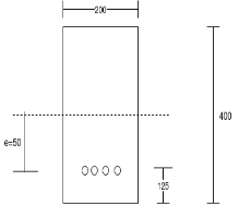 Area of beam size=A=b.d=200
2) Moment of inertia 
3) Initial prestressing force =

4) We know, stress in concrete at the level of steel


5) Modular ratio=
6) Calculate losses
a) Loss of prestress due to elastic shortening of concrete =
= 6.667*6.018
=40.13
Prestressing force causing long term deformation


b) Stress in concrete causing long term deformation


∴Loss due to creep =

c) Loss due to shrinkage strain =
=
d) Loss due to relaxation of steel =

e) Total loss=a+b+c+d
=40.13+85.07+60+52.9935
=238.20
f) Total percentage loss of prestress =

Problem no 06:-A post tensioned beam 200mm wide and 400mm deep is prestressed with 8 wires of 7mm diameter with their centroid located at 125mm from soffit, the cables streatch with straight. Determine the total percentage loss. Take
1) Prestressed applied by jack=1100 
2) Length of the beam=15m
3) Slip in anchorage =1.5m
4) Coefficient of friction for wave effect k=0.0020/m
5) Shrinkage strain=0.0002 instead 0.0003; 
Given Data:-
b=200mm ;D=400mm; ;soffit distance=125mm from bottom; eccentricity=
 ;
; 
Solution:-
1) Area of beam=A=bd=200*400 =
2) Moment of inertia 
3) ∴Loss of prestress due to slip =
4) Prestressing force transferred to beam=
5) ∴Stress in concrete causing long term deformation


6) Calculate losses
a) Loss due to creep =

b) Loss due to shrinkage strain=

c) Loss of force due to friction


∴Loss of stress in steel 
d) Loss due to relaxation of steel=
e) Total losses=a+b+c+d+e
=

f) ∴Percentage loss of stress=
Problem no 07:-A concrete beam is post-tensioned by a cable carrying an initial stress of 1100  . The slip at the jacking end is 10mm. Modulus of elasticity of steel is 210
  . Estimate the percentage loss of stress in steel due to anchorage slip only if the length of the beam is
a) 20m
b) 45m
Given Data:-Initial stress  , Anchorage slip
Modulus of elasticity = : Length
Solution:- we know loss of stress due to anchorage slip=
a) For span L=20m
Loss of stress due to anchorage slip = 
∴% loss of stress =
b) For span L=45m
Loss of stress due to anchorage slip =
∴% loss of stress =
c) For span L=60m
Loss of stress due to anchorage slip =
∴% loss of stress =
Above all three case shown in
The length of span increase than loss of stress reduces and also decreases % of loss of stress.
Problem no 08:-A pre-tensioned beam of rectangular cross-section,200mm wide and 450mm deep is prestressed by 10 wires of 8mm wires located 150 mm from the soffit of the beam. If the wires are initially tensioned to a stress of 1200  , calculate their stress at transfer and the effective stress after all losses given the following data
| Upto time of transfer | Total |
Relaxation of steel | 40  | 80  |
Shrinkage of concrete | 100  | 300  |
Creep coefficient | - | 1.8 |

Given Data:- b=200mm d=150mm ;  soffit 150mm;
Initial stresses 
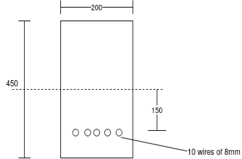 Creep coefficient=
 ;Modular ratio
=
Solution:-
Area of section 
Moment of inertia 
Area of wires=
Prestressing force 
Stress in concrete at level of steel 
[….. ]
]
=6.70+ 2.23
=
a) At transfer
Loss due to relaxation =40 (Given)
Loss due to elastic deformation=
Loss due to shrinkage=
Total losses =40+59.56+21=120.56
∴Stress in steel at transfer=
b) Effective stress after all losses
Loss due to relaxation Loss=80  (Given)
Loss due to elastic deformation=
Loss due to shrinkage=
Loss due to creep of concrete=
=1.8*8.93*6.67
=107.21
Total loss=80+59.56+63+107.21
=309.77
∴Stress in steel at transfer=
Problem no 09:-A post tensioned beam 250 400mm deep is prestressed by 12 wires of 7mm diameter initially stressed to 1200
  . The cable profile is parabolic with zero eccentricity at supports and 120mm at the centre. The span of the beam is 10m. Estimate the loss of prestress due to various factor and the percentage loss for the following data grade of concrete
  shrinkage strain=
 Relaxation of stress in steel 4% creep coefficient=1.6, coefficient of friction between cable and duct is 0.55 wave effect 0.0015/m length, anchorage slip 3mm. Take
  in
in 
Given Data:- b=200mm ;D=400mm; Initial stresses
  ;
;  ; Span=L=10m;
  Shrinkage strain=
 ;Relaxation of stress in steel=4% ;Creep coefficient=
 ;Coefficient of friction=0.55=
Wave effect=K=0.00015/m; Anchorage slip= =
= Modular ratio
Solution:-
Area of section A =
Moment of inertia=
Area of wire==
Prestressing force P=
Stress in concrete at level of steel 
Average eccentricity 


a) Loss due to shrinkage=

b) Loss due to relaxation=4% of initial stress=
c) due to creep=
=1.6*5.83*8.19
=76.39
d) Loss due to slip=
e) Loss due to friction=
 =cumulative angle of rotation
=

f) Total loss=63+48+76.39+63+81.36

g) Percentage of loss=
Problem no 10:-A prestressed concrete beam 300mm is prestressed by tendon of area 800
 at a constant eccentricity of 100mm with an initial stress of 1050
  . Span of the beam is 10.50m, with the following additional data, calculate losses for both pre and post tensioning cases. Take
  ;Anchorage slip=1.5mm; K=0.0015m; Ultimate creep strain:
  ;stress for pretensioning and
  ;stress for post tensioning; shrinkage of concrete=

Relaxation of steel=25%
Given Data:- b=300mm ; D=600mm ; Area of tendon=800 ; eccentricity e=100mm ; initial stress
  ; Span of beam L=10.50m;
Solution:- Pre-Tensioning
1) Area of beam A=b.d=300
2) Moment of inertia =
3) Initial prestressing force in tendon P=800
4) Modular ratio m=
5) Eccentricity e=100mm
6) Calculate stress in concrete at the level of steel


7) Calculate losses
a) Elastic loss 
b) Loss due to creep:-
Force causing long term losses = (1050 - 37.362)
=1012.638N
By proportioning, stress causing long term losses at level of steel


Now, creep strain=
Total creep strain=
=
Loss due to creep=
=
c) Loss due to shrinkage=shrinkage strain*


d) Relaxation loss=2.5%=
Total losses = a+b+c+d
=37.362+48.804+63+26.25
=175.416
B) Post Tensioning
a) Loss due to slip=
b) Friction loss:-
Stress at jacking end causing long term deformation

K=0.0015m ; l=10.50m
Stress at other end =


Friction loss= =1020-1004.06=15.94
 ------------(b)
c) Loss of stress due to creep
Average stress causing long term deformation=

Average stress in concrete at the level of steel = 
= 
Creep strain=
Loss of stress in steel due to creep =
=
d) Loss due to shrinkage=Shrinkage strain*


e) Relaxation loss 25%=
Total average loss=a+b/2+c+d+e

=
Therefore Total loss in pre tensioning=
Total loss in post tensioning=
Desirable distribution of initial compressive stress in concrete
The distribution of the initial compressive stress in concrete has a great bearing on the size of the beam and the load bearing capacity. Two methods are available for distributing prestress, uniform pressure distribution and non uniform pressure distribution. The non uniform pressure distribution has the advantages, that the chosen pressure distribution is such that the dead load of the member can be counterbalanced. We know the moment due to dead load varies along the span and is maximum at the centre. Hence, it is necessary that the various critical sections have to be analysed while designing. This is made by wearing the pressure distribution for various sections along the beam. This can be achieved by wearing the location of the centre of gravity of the steel with respect to centre of gravity of concrete.
a) By providing curved tendons in post-tensioned beams
b) By wearing the cross sections in pre tensioned beams
Where possible a small upward camber should be given to the beam. By this arrangement it is possible to keep the cable straight. End eccentricity can be avoided and the maximum eccentricity can be provided at mid span. Since in this arrangement, the cables are straight considerable frictional resistance is minimised.

a) Bent or curved tendons in post tensioned beam
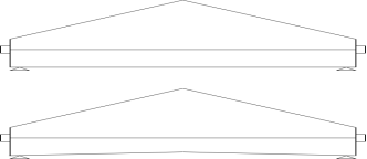
b) Varying sections in pretensioned beam
Effect offloading on the stress on wires in the tendons.
Consider a prestressed concrete beam of span L provided with a tendon at an eccentricity e. If the prestressing force, The beam is subjected to a hogging moment  The beam will therefore deflect. The slope at each and due to this deflection is
  If now, beam is subjected to a downward external load there will be deflections and hence there will again be a slope at each end. Suppose The beam carries a uniformly distributed load of w per unit run over the whole span, the slope at each end will be
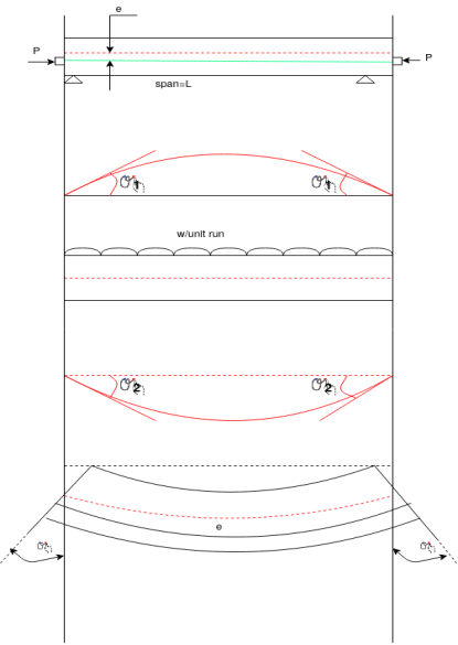
Net slope at each end 
Extension of the tendon due to the net defloration =2eθ
Increase in strain in the tendons=
Increase in stress in the tendons=
Tendon with parabolic profile
The figure shows a prestressed beam carrying an external uniformly distributed load w per unit run. The tendon is provided with a parabolic profile. When the cable is provided with a parabolic profile, it will exert a uniform upward pressure  per unit run on the beam and will therefore receive a downward uniformly distributed load
  per unit run.
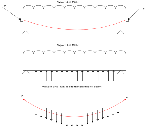
We have studied in the theory of cables carrying uniformly distributed load, on the whole span.
Horizontal reaction at each end of the cable 
Where h is the dip of the cable centre below the ends of the cable.
Making the approximation 
We get, 

P=applied force
h=dip of cable at centre
l=span of beam
Hence a parabolic tendon carrying a tension P will provide and upward uniformly distributed load or pressure.
Hence the upward uniform pressure supplied by the parabolic tendon will counter act a part of the external downward uniformly applied load.
The net downward loading on the beam is therefore equal to ( per unit run.
a) If net unbalanced load is downward then 
b) If net unbalanced load is upward then 
 Problem no 01:-Figure shows a prestressed concrete beam provided with a tendon having a parabolic profile. If the total external load on the beam is 35 KN/M on the whole span, calculate the extreme stresses for the mid span section. The tendon carries a prestressing force of 1000 KN.
Solution:-
Area of a beam=
Section modulus of the section 
Span of tendon L=6m=6000mm
Dip of tendon h=100mm=0.1m
Upward uniformly distributed pressure provided by the cable 


Net downward load on The beam=35-22.22=12.78KN/M
Maximum bending moment 
Extreme stress for the mid span=


Extreme stress at top=4.17+2.40=6.57
Extreme stress at bottom=4.17-2.40=1.77
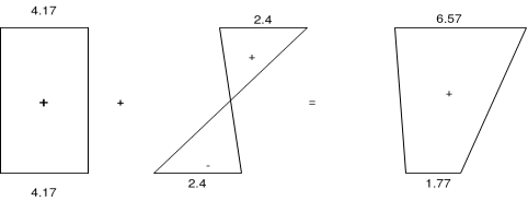
Problem no 02:- Determine the profile of a load balancing cable for a beam of span 6 meter carrying on all inclusive load of 40 KN/M. The prestressing force in the tendon is 1200KN. The beam sections is 400mm×600mm
Solution:- let the dip of the cable be h metres. Upward pressure provided by the parabolic cable=
In order this upward pressure mein fully balance the external loading; 40KN/M
Equate 266.67h=40 i.e. h=0.15m=150mm
Hence the cable should be provided with a central dip of 150mm
The uniform stress for the beam section , 
Problem no 03:- if the prestressing force in the tendon is P for the beam shown in figure. Find the central dip h required to fully balance a concentrated load w applied at mid span.

Solution:- let  Be the inclination of the tendon with the horizontal.
Upward force provided by the tendon at the centre=
If this force should balance the applied downward load 

Problem no 04:-Find the cable dip h for the beam shown in figure so that the applied external loads may be balanced. The tension in the cable is P
Solution:- Let  be the inclination of the and parts of the cable with the horizontal.

Approximately upward force provided at each one third span point by the cable=
In order the external load may be balanced i.e.

