UNIT 2
Prestressed Concrete - Design
Simply supported rectangular and flanged sections for
1) Flexure
2) Share including end block
Design of one way and the two way post tensioned slabs (Single Panel Only)
Limit state of collapse:- Flexure [IS 1343-2012,Clause no 23.1,pp-31]
Assumptions
Design for the limit state of collapse in flexure shall be based on the assumptions given below:-
a) Plan sections normal to the axis remain plane after bending.
b) The strain in the bonded reinforcement or bonded prestressing Steel weather in tension or in compression is the same as that in the surrounding concrete.
c) The maximum strain in concrete at the outermost compression fibre is taken as 0.0035 in the bending.
d) The relationship between the compressive stress distribution in concrete and the strain in concrete may be assumed to be rectangular, trapezoid, parabola or any other shape which results in prediction of strength in substantial agreement with the results of tests. An acceptable stress strain curve is given in below figure.
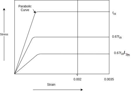
For design purposes, the compressive strength of concrete in the structure shall be assumed to be 0.67 times the characteristic strength. The partial safety factor  =1.5 shall be applied in addition to this
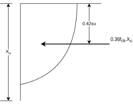
Area of stress block=0.36 
Depth of centre of compressive force=0.42
e) The tensile strength of the concrete is ignored.
f) The stresses in bonded prestressing tendons, weather initially tensioned or un tensioned and in additional reinforcement are derived from the representative stress strain curve for the type of Steel used given by the manufacturer or typical curves given in below figure.
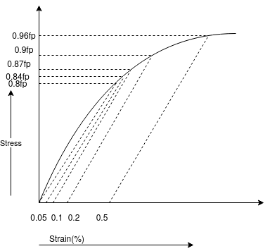
For prestressing tendons and in IS-456 for reinforcement. For design purposes, the partial safety factor  equal to 1.15 shall be applied. In addition, the tendon will have an initial prestrain due to prestress after all losses.
For members with permanently unbonded internal or externally prestressed tendons, the deformation of the whole member shall be taken into account for calculating strain and stress in the tendon at ultimate condition. In the absence of rigorous analysis, the strain is unbonded tendon shall we assumed not to increase above the initial value due to prestress after all losses.
Design formulae:-[IS 1343-2012,Clause no 23.1.2,pp-32]
In the absence of an analysis based on the assumptions given in 23.1.1 the moment of resistance of rectangular sections and flanked the sections in which the neutral axis lies within the flanged may be obtained by the procedure given in IS 1343-2012 Annex-D pp-51
For flanged sections in which the neutral axis lies outside the flange, the moment of resistance shall be determined using assumptions given in 23.1.1
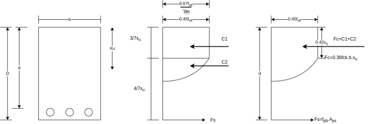
The moment of resistance is obtained from the equation

Where,
 = moment of resistance of the section
 = tensile stress in the tendon at failure
 = effective prestress in tendon
 =area of pretensioning tendons in the tension zone.
d= effective depth to the centroid of the Steel and
 = neutral axis depth
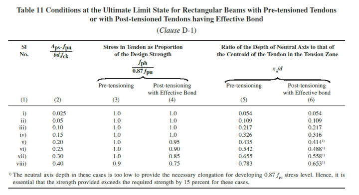
For pretensioned members and for post-tension members with effective bond both the concrete and tendons, values of  are given in table 11 it shall be ensured that the effective prestress
  after all losses is not less than 0.45
  where
where  is characteristic tensile strength of tendon. Prestressing tendons. Prestressing tendons in the compressive zone should be ignored in strength calculation when using this method.
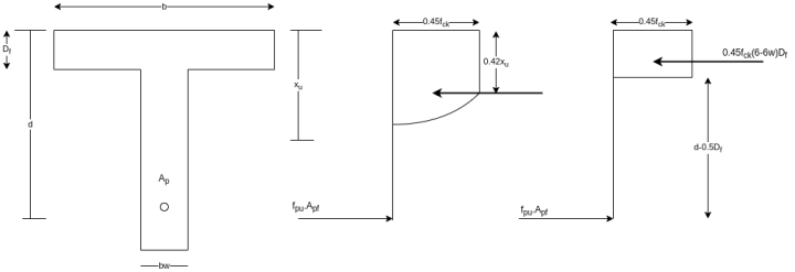
The ultimate moment of resistance of flanged sections in which neutral axis falls outside the flange is computed by combining the moment of resistance of the web and flange portion and considering the stress blocks shown in figure below.
If  area of prestressing Steel for web;
 = area of prestressing Steel for flange
 = thickness of flange, then
But 
After evaluating  , the value of
  is obtained as
For the effective reinforcement ratio  the corresponding values of
  and
and  are interpolated from table 11 the ultimate moment of resistance of the flanged the section is expressed as

Problem N0. 01:-A pretensioned beam of rectangular section 350mm wide 900mm overall depth is Prestressed by 720  of high tensile Steel wires at an eccentricity of 250mm If
  estimate the ultimate flexure strength of the section as per IS-1343-2012 café provisions
Given data:- b=350mm ; d=900mm ; 
 prestressed by tendon of effective area
  eccentricity e=250mm

Solution :-
We know the effective reinforcement ratio is given by 
From table 11 PP.51 the corresponding values are interpolated as
Calculate  in pretensioned beam
 |  |  |
0.05 | 1.9 | 0.109 |
0.08 | x | y |
0.10 | 1.0 | 0.217 |
X=1.0
0.05 | 0.109 |
0.08 | y |
0.10 | 0.217 |


=0.1738


Moment

=


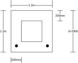
Problem N0. 02:-A Pre tensioned concrete of box section 1.2m×1.2m overall dimensions has a uniform wall thickness of 200mm. The girder is post tensioned by high tensile wires of area 2400  located at an effective depth of 1000mm. If
  and
and  Calculate the ultimate flexural strength of the box girder section.
Given data:-b=1200mm; d=1000mm, t=200mm
Prestressed by tension of effective area  =2400
=2400
To find:- moment  =?
=?
Solution:- We know that the effective reinforcement ratio is given by 


From table 11 PP-51 the corresponding values are for pre tensioning

 =1.0×0.87×1000=870 N/mm².

We know


Problem N0. 03:-A pretensioned prestressed concrete beam having a rectangular section with the width of 150mm and overall depth of 350mm is prestressed by tendons of effective area 461 . Assuming the characteristic strength of concrete and steel at 40 & 1600 N/
 estimate the ultimate flexural strength of the section using the provisions of the IS code 1343-2012
Solution:-b=150mm ; D=3500 mm ;  =Prestressed by tendon of effective area=461
d=300mm ;
We know the effective reinforcement ratio is given by 
From table 11 PP-51, the corresponding values are
 =0.9×0.87

We know


Problem N0. 04:-A pretensioned T-beam has a flange width of 300mm and thickness of 20 mm. The rib is 150mm wide by 350mm deep. The beam is Prestressed by tendons of c/s area 200 at an effective depth of 500mm . If
  estimate the flexural strength of the section using the IS 1343-2012
Solution:-b=300mm  20 mm.
  D=350mm ;
 =Prestressed by tendon of effective area=200
d=500mm ;
We know the effective reinforcement ratio is given by 
From table 11 PP-51, the corresponding values are
 =1×0.87

The assumption that neutral axis falls within the flanges is correct. Hence, ultimate flexural strength of the T-section is computed as,
We know


Problem N0. 05:-Post tensioned prestressed concrete bridge deck slab has the following design parameters. Estimate the ultimate flexural strength of the slab according to the IS code specifications.
b=1000m 
Solution:. We know,
We know the effective reinforcement ratio is given by 
From table 11 PP-51, the corresponding values are
 =1×0.87


Problem N0. 06:- A prestressed concrete beam of rectangular cross-section carries a UDL of 10KN/M over a span of 10m including its self weight design the section. The characteristics strength of steel and concrete are 1500MPa and 40MPa respectively. AMIE-2016
Given data:- W=UDL=10KN/M: Span=L=10m 

To find :- b,d
Solution:-Factored load 
Factored bending 
Assume  (Assume)
We know  From Table-11 [IS-1343-2012 PP-51]


d=380mm 
b=200mm 
If cover is 60mm : D=380+60=440mm
Moment of resistance with respect to steel 
 …….
……. 


Provide 13-8mm high tensile prestressing steel wires at an effective cover of 60mm

We know
 (Assume)


Problem N0. 07:-A pre tensioned T section has a flange width 5500mm and thickness of flange is 250mm. The rib is 250mm wide by 350 mm deep. The effective depth at which high tensile Steel of area 400 is provided by 500mm.
Given  Estimate the flexural strength of the T section.
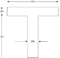 Given:- b=500mm, d=750mm,
Solution:-

Assuming from Table-11 :PP-51
 |  |  |
0.025 | 1.0 | 0.054 |
0.028 | X | Y |
0.050 | 1.0 | 0.109 |
Calculate X & Y by interpolation
X=1.0 
=0.0606
 =1×0.87

We know that
 calculate moment


Problem No. 08:-A Precast pretensioned t beam has a flange width of 1200mm and tk=150mm. The width and depth of the rib are 300mm and 1500mm respectively. The high tensile Steel tendons of c/s area 4700 are located at an effective depth of 1600mm. If the characteristic strength of concrete and steel are 40 and 1600
  respectively. Calculate the flexural strength of the T-section using IS café provisions.
Solution:- b=1200mm, 
The area of Steel beam large, the neutral axis depth is likely to exceed the thickness of the flange.


Hence,

From table 11 PP-51, the corresponding values are interpolated as
 =1×0.87


Moment

=1392×3181.25×(1600-0.42×896)+0.45×40×(1200-300)×150×(1600-0.5×150)


=9115.75 KN.m
Problem N0. 09:-A post tensioned bridge girder with bond attendance is of box section having overall dimensions 1200mm wide and 1800mm deep, with wall thickness of 150mm. The high tensile Steel located at an effective depth of 1600mm has a c/s area of 4000 If the characteristic strength of concrete and steel are 40 and 1600
  respectively. Estimate the flexural strength of the box girder using IS code
Solution:-b=1200mm. D=1800mm, 

We know,


Calculate ratio 
From table-11 PP-51, the corresponding values are interpolated as


We know, Moment

=1322×2481.25×(1600-0.42×662.4)+0.45×40×(1200-300)×150×(1600-0.5×150)


=8042.75 KN.m
Problem N0. 10:-Post tensioned bonded prestressed concrete beam of unsymmetrical t section has a flange width of 1800mm and thickness of flange is 300mm and thickness of rib is 300mm. The area of high tensile steel is 6000  located at an effective depth of 2000mm. If the characteristic strength of concrete and steel are 45
 and 1800
 respectively, calculate the flexural strength of the t section.
Given data:-b=1800m; 
Solution:-we know that
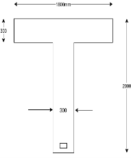


Calculate ratio 
From table-11 PP-51, the corresponding values are interpolated as
 |  |  |
0.050 | 1.0 | 0.054 |
0.0625 | X | Y |
0.100 | 1.0 | 0.217 |
Calculate x and y by interpolation
X=1.0 

y=0.136
x=1.0 and y=0.136


Problem N0. 11:-A double T section having a flange 1800mm wide and 300 mm thick is Prestressed by 6000 of high tensile Steel located at an effective depth of 2000mm. The ribs have a thickness of 300 mm each if the cube strength of concrete
  and tensile strength of steel is
  determine the flexural strength of the double t girder using IS-1343-2012
Given data:- b=1800m; 
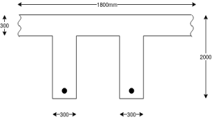 Solution:-we know that


Calculate ratio 
From table-11 PP-51, the corresponding values are interpolated as
 |  |  |
0.050 | 1.0 | 0.109 |
0.0650 | X | Y |
0.100 | 1.0 | 0.217 |
Calculate x and y by interpolation
X=1.0 

Y=0.1414
X=1.0 and y=0.1414


The ultimate moment capacity of the T-section


The ultimate share resistance of the concrete alone,  should be considered at both conditions, uncracked and cracked in flexure the lesser value taken and if necessary, shear reinforcement provided.
A) Section uncracked in flexure[ IS 1343-2012, Clause no. 23.4.1, Pp-32]
The ultimate share resistance of a section uncracked in flexure,
 is given by,

Where,
b=breadth of the member which for T,I and L beams should be replaced by breadth of the rib 
D=overall depth of the member
 =maximum principal tensile stress given by
  taken as positive where
  is the characteristic compressive strength of concrete.
 =compressive stress at centroidal Axis due to prestress taken as positive in placed members where the centroidal axis occurs in the flange, the principal tensile stress should be limited to
  at the intersection of the flanged web ; in this calculation, 0.8 times of the stress due to pressure stress at this intersection may be used, in calculating
  4 section and cracked in flexure and with inclined tendons or vertical prestress, the component of prestressing force normal to the longitudinal axis of the member may be added to
B] Section crack in flexure [ IS 1343-2012, Clause no. 23.4.2, Pp-33]
The ultimate shear resistance of a section cracked in flexure,  is given by

Where,
 =effective prestress after all losses have occurred, which shall not be taken as greater than 0.6
 = characteristic strength of prestressing Steel
 =Ultimate shear stress capacity of concrete obtained from IS 1342-2012,table 8 PP-33
b=breadth of the member, which, for flanged sections, shall be taken as the breadth of the web 
d=distance from the extreme compression fibre to the centroid of the tendons at the section considered
 =moment necessary to produce zero stress in the concrete at the depth

 =is the stress due to prestress only at a depth of d and distance Y from the centroid of the concrete section which has second moment of area I
V and M= shear force and bending moment respectively, at the section due to ultimate loads.
 should be taken as not less than
The value of  calculated at a particular section may be assumed constant for a distance equal to d/2, measured in the direction of increasing moment, from that particular section.
For a section cracked in flexure and with inclined tendons, the component of prestressing force normal to the longitudinal axis of the member should be ignored.
Shear reinforcement[ IS 1343-2012, Clause no. 23.4.3, Pp-33]
When V, the shear force due to the ultimate loads, is less than  , the shear force which can be carried by the concrete, minimum shear A/F should be provided in the form of stirrups such that

Where,
 = total cross sectional area of stirrups let's effective in share
b= breadth of the member which for T, I and L beam should be taken at the breadth of the rib 
 = stirrup spacing long the length of the member, and
 = Characteristic strength of the stirrup reinforcement which shall not be taken greater than 415
However, share reinforcement need not be provided in the following cases
a) Where V is less than 0.5
b) In members of minor importance
When V exceeds  , share reinforcement shall be provided such that,

In rectangular beams, at both corners in the tensile zone, a stirrup should pass around a longitudinal bar, a tendon or a group of tendons having a diameter not less than the diameter of the stirrup the depth  is then taken as the depth from the extreme compression fibre either to the longitudinal bars or to the centroid of the tendons whichever is greater.
The spacing of stirrups along member should not exceed  nor 4 times the web thickness for flanged members. When V exceeds
  the maximum spacing should be reduced to
  the lateral spacing of the individual legs of the stirrups provided at a cross section should not exceed
Maximum shear forces:-
In no circumstances should the shear force V, due to ultimate loads, exceed the appropriate values given in [ IS 1343-2012]table no.09 PP-34 multipled by bd.
Concrete grade | M-30 | M-35 | M-40 | M-45 | M-50 | M-55 and over |
Maximum shear stress N/mm² | 3.5 | 3.7 | 4.0 | 4.3 | 4.6 | 4.8 |
Problem No. 01:-The support section of a PSc Beam 100mm wide and 250mm deep is required to support an ultimate shear force of 150KN. The compressive prestress at the centroidal axis is 5Mpa. Use M-40 concrete and Fe-415 Steel for stirrups. The concrete cover to shear reinforcement is 50mm. Design suitable shear reinforcement.
Solution:-b=100mm ; D=250mm ;  =150KN ;
  ;
;  d'= 50 d=D-d'=250-50=200mm
Consider a section uncracked in flexure[ IS 1343-2012, Clause no. 23.4.1, Pp-32]


Since , shear reinforcement is to be provided.
Using 2 legged 8mm diameter vertical stirrups, we have


 =71.53mm ≈70mm
Maximum spacing
1) 0.75A=0.75×200=150mm
2) 4b=4×100=400mm
Problem No. 02:The support section of PSC Beam 200mm×400mm is required to support ultimate shear force of 220 KN. Compressive prestressed at centroid is 5 Cover to tension reinforcement is 50mm. Design suitable reinforcement using Fe-250 steel.
Given data:- b=200mm ; D=400mm ;  ;
;  cover=50mm
  ultimate shear force V=220KN
Solution:-consider a section uncracked in flexure [ IS 1343-2012, Clause no. 23.4.1, Pp-32]
At support section, 
We know 


Therefore shear reinforcement is to be provided using two legged 8mm diameter vertical stirrups, we have


Maximum spacing
1) 0.75 0.75×350=262.5mm
2) 4b=4×200=800mm
Provide 8mm two legged stirrups at 140mm c/c near support.
Check for minimum 

Problem No. 03 :- The support section of PSC Beam 150mm×350mm is required to support and ultimate shear force of 80KN. The compressive prestress at centroidal axis is 5mpa,  concrete cover is 50mm. Design suitable shear reinforcement.
Given:-b=150mm ; D=350mm ;  =150KN ;
  ;
;  cover=50mm
Solution :- consider a section uncracked in flexure[IS 1343-2012, Clause no. 23.4.1, Pp-32]
At support section, 
We know, 


 when the shear force due to the ultimate load is less than shear resisted bike can create alone.
Provide minimum shear reinforcement in the form of stirrups such that  [ IS 1343-2012, Clause no. 23.4.3.1, Pp-33]
Use 2 legged 8mm diameter vertical stirrup


Maximum spacing
1) 0.75 0.75×300=225mm
2) 4b=4×150=600mm
Provide two legged stirrups at 225mm c/c near support.
Problem No. 04 :- A Post-tensioned simply supported beam is 20m span. Using Fe-415 reinforcement, design the beam shear reinforcement. Using IS 1343-2012, b=200mm,D=300mm,  =180KN,
  effective cover 50mm, compressive stress is
Given data:-span=L=20m ; b=200mm ; D=300mm ; shear force  =180KN
  effective core=d'=50;
Design a shear reinforcement
Solution:-We know : concrete shear strength 
Tensile strength of concrete 


Compaired
As per Clause No. 23.4.3.2 PP-33

Assume 2 legged 8mm diameter stirrups


Maximum spacing of stirrups
1) 0.75
2) 4b=4×200=800mm
Hence provide 2 legged 8mm diameter e 180mm c/c by shear force diagram
From similar triangle 
X=6.45m
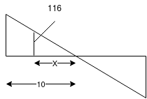
Hence, provide 2 legged 8mm diameter e 180mm c/c for 6.45m on either side and the remaining length provide 2 legged 8mm diameter e 140mm c/c
Problem No. 05 :-The support section of a PSC Beam 200mm wide and 450mm deep is required to support an ultimate shear force of 200KN. The compressive prestress at the centroidal axis is 6 MPa. Use  and Fe-415 grade of concrete and steel respectively for stirrups. The concrete cover to shear reinforcement is 50mm. Design suitable shear reinforcement.
Given data:- b=200mm D=450mm ; shear force  ;
; 
Solution
Consider a section uncracked in flexure [IS 1343-2012, Clause no. 23.4.1, Pp-32]

Where 


Shear reinforcement is to be provided
Using 2 legged 8mm diameter vertical stirrups we have


But maximum spacing
1) 0.75
2) 4b=4×200=800mm
Problem No. 06 :-The support section of PSC Beam 200mm×400mm is required to support ultimate shear force of 220KN compressive prestress at centroid is 5 Cover to tension reinforcement is 50 mm.
If the cables are having parabolic profile with maximum eccentricity of 100mm at mid span and zero eccentricity at the ends design the shear reinforcement at support. Given span=10m and total prestressing force=300KN
Given data:- b=200mm ; D=400mm ; cover=50mm  ultimate shear force V=220KN
Solution:-consider a section uncracked in flexure at support section ; [IS 1343-2012, Clause no. 23.4.1, Pp-32]

We know 


In this case slope of cables at support inclination

Vertical component of prestressing force=P.I
=300×0.04=12KN
Total 
Net shear force=220-178.66=41.34KN
Use 8mm 2 legged stirrups


But maximum spacing 30.75 =0.72×350=262.50mm
46=4×200=800mm
Provide 8mm two-legged stirrups at 185mm c/c near support
Minimum 
Problem No. 07 :-A post tensioned beam of rectangular cross section 200mm wide and 400mm dip is 10m long and carries and applied load of 8KNM on The Beam. The effective prestressing force in the cable is 500KN. The cable is parabolic with zero eccentricity at the support and maximum eccentricity of 140mm of the centre of the span. Calculate principal stress at the supports. What will be the magnitude of principal stresses at the support in the absence of prestress.
Given data:-b=200mm D=400mm ; L=10m =10000mm
Live load per metre= 8KN/m prestressing force P=500KN cable position=parabolic with 0 eccentricity at the support and maximum eccentricity e=140mm
Calculate:-
1) Principal stress at the supports
2) Principal stress at the supports in the absence of prestress
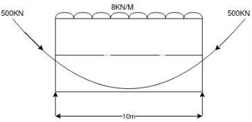
Solution:-
Self weight of per metre=b×D×γ
=0.20×0.40×1×24
=1.92KN/m
Live load=8.0KN/m
Total load=8+1.92=9.92KN/M ≈10KN/m
1) Support reaction= 
2) Calculate inclination θ= 
3) Calculate net shear force
Vertical component= 
Net shear force=50-28=32KN
4) Calculate axial stress 
5) Calculate maximum shear stress at support=1.5 
Ʈ=0.4125
6) Calculate maximum and minimum stress


II) Stress at the absence of prestress
Support reaction=50KN
Actual shear stress =
Hence, in absence of prestress


Problem No. 08 :-The cross section of a prestressed concrete beam is an unsymmetrical T-section with the following dimensions overall depth-1200mm ; web=200mm and flange=1000×200mm. At a particular section The Beam is subjected to ultimate moment and shear force of 2, 000K.N.M and 250KN respectively. Design the beam for shear with the following data, grade of concrete M-40, effective depth=1100mm ;
Effective prestress at extreme tensile force of The Beam= 19.30mpa[ SPPU-ISE-2015]
Given data:-
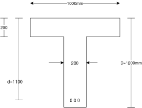


1) Consider sections cracked in flexure[IS 1343-2012, Clause No. 23.4.2 , PP-33]


 = Ultimate shear stress capacity of concrete obtained from table-8 PP-33 It's depend upon Pt%
Pt% =
From table  from M-40 grade concrete

Calculate I & Y


Calculate moment of inertia


Hence, balance shear = =250-230.437=19.563KN
Use 8mm diameter two legged stirrups the spacing of the stirrups is

Maximum permissible spacing=0.75d=0.75*1100=825mm

Provide nominal shear reinforcement
Provide 2-legged stirrups e 800mm c/c
Problem No. 09 :-An unsymmetrical section has the following sectional details as shown figure shear force across section =250KN Effective prestressing force in cable 1500KN. Inclination of tendon at given section  fibre stress distribution across the section
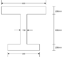 at the top edge linearly reducing to zero to the bottom. Compute and compare the principal stress at the centroidal axis and the junction of web with lower flange.
Given data:-figure as shown in
Effective prestressing force in cable=1500 KN
Fibre stress distribution across the section= 12 
Solution:-area of section= (600×200)+(150×800)+(300×200)
=
1) Calculate centroid from bottom


2) 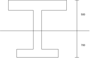 Calculate moment inertia


Ixx=[(600*2003)/12+(600*200)(500-100)2]+[(150*8003)/12+(150*150)(700-600)2]


Problem No. 10 :-The cross section of a prestressed concrete beam of an unsymmetric t section has the following data
1) Overall depth=1400mm ;
2) Thickness of web=200mm
3) Distance of bottom fibre=850mm
4) Effective depth d=1100mm
5) Moment of inertia =I= 
6) cube strength of concrete 
7) Area of prestressing Steel 
8) Tensile strength of tendons=
9) Effective prestress at the extreme tensile force of The Beam=
Design the shear reinforcement at the section, if the ultimate moment is 2100 KN-m and ultimate shear force is 300KN. Use Fe-415 steel for stirrups.
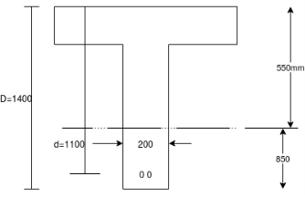 Given data:-as shown in figure.
M.I.=I=


Solution
1) The flexural stress at this section where bending moment is 2100KNM is

Hence the section would have cracked

Now, 
From table number 8 PP-32

2) The flexural shear resistance of the section is[IS 1343-2012, clause no 23.4.2, pp-33]

Where; 
b=200; d=1100mm V=300KN; M=2100 KNM 


Hence, provide shear reinforcement using 8mm, 2 legged Fe-415 stirrups 


Maximum spacing
1) 0.75
2) 4b=4×200=800mm
Provide 8mm, 2 legged stirrups at 800mm c/c
Check for minimum 


Hence reduce the spacing
 say 750mm
Provide shear reinforcement with 8mm, 2 legged Fe-415 stirrups at 750mm c/c
In pretensioned beams, there is a gradual transfer to the prestressing force to the surrounding concrete. As an effect coma a uniform distribution of stresses is present after a certain length from the support section.
In post tensioned members, the prestress wires are introduced and then stressed and anchored at the ends. As a result of this, large forces are concentrated over a relatively small areas. This results in the development of transverse and shear stresses. These high stresses develop in concrete at the beam ends.
The zone between the end of the beam and the section where only longitudinal stresses exist is called end block or anchorage zone or transfer zone. This zone is of beam length equal to the depth of the beam.
The transverse stresses developed in the anchorage zone are tensile in nature over a large length and since concrete is weak in tension. Hence, from the point of view of the designer, it is essential to have a good knowledge of the distribution of stresses in the anchorage zone, so that he/she can provide and adequate amount of steel, properly distributed to sustain the transverse tensile stresses.
Permissible bearing stress
IS :1343-2012 Cl No. 19.6.21-a recommends that the permissible stress on concrete, after accounting for all losses due to relaxation of steel, elastic shortening, creep of concrete, sleep in anchorages shall be

Whichever is smaller
Where,
 cube strength at transfer
 =bearing area
 =punching area
- Permissible stress may be increased by 25% at the time of transfer provided the value does not exceed 
- The effective punching area shall only be the contact area of the anchorage devices which is circular in shape commercial be replaced by a square of equivalent area the bearing area shall be the maximum area of that portion of the member which is geometric li similar and concentric to the effective punching area.
- In case of embedded anchorages coma bearing stress shall be investigated after accounting for the surface friction between the anchorage and the concrete.
- Where a number of encourages are used, the bearing area shall not overlap, where there is already a compressive stress prevailing over the bearing area comedy total stress shall not exceed the limiting values specified above.
- For stage stressing of the cables, the adjacent unstressed anchorages shall be neglected while determining the bearing area.
Effective punching area and bearing area
The effective punching area is the area of the anchorage plates/device and the bearing area is the maximum area of that portion of the member which is geometrically is similar and concentric to the effective punching area.
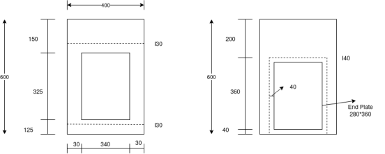
Use fig- a
Effective punching area=340×325-cross section area of ducts
Effective bearing area=(340+2×30)×(325+2×30)=(400×385)
Fig-b
Effective punching area=(280×360)
Effective bearing area=(280+2×40)×(360+2×40)

The case of freyssinet system with end anchorage
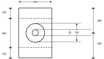
D=150mm ; d=50mm
Punching area=

Bearing area also should be square and it should be maximum. In this case width of the beam restrict the size
Hence the size of the square is 400mm
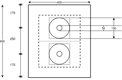

In case of freyssinet system
Equivalent square of size=
=133mm
Two squares of maximum size, without overlapping are to be fitted. It is governed by the distance between the two squares in the vertical direction.

Half the size of the square=
Size of the square=2×191.50=383mm
Bearing plate= for each cable
Punching area= for each cable.
Problem no. 01:-figure shows the end view of a post tensioned beam with a common bearing plate for 6 cables, each of 18mm diameter. The diameter of duct for each cable is 40mm. Check the bearing stress. Take, strength of concrete at transfer 
Initial tension in each tendon=
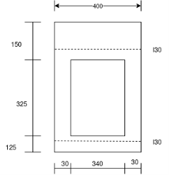
Solution:-area of cable=

Punching area=(340×325)-7539.83

A bearing area=400×(325+30+30)

We know as per IS 1343-2012 Cl no. 19.6.2.1-a pp-26


We know prestressing force
P=


Actual bearing stress=

Hence safe in bearing
The forces on the end block of a post tensioned prestressed concrete member are shown in figure below.
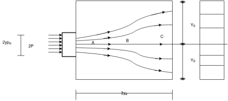
- A physical concept of the state of stress in the transverse direction, that is normal two planes parallel with the top and bottom surfaces of the beam may be obtained by considering these lines of force as individual fibres acting as curved struts inserted between end force 2P and the main body of the beam.
- The curvature of the struts, being convex towards the centerline of the block, induces compressive stresses in zone-A.
- In zone B the curvature is reversed in direction and the struts tend to reflect out words, separating from each other and consequently developing transverse tensile stresses.
- In zone C, the struts are straight and parallel so that no transverse stresses are induced only longitudinal stresses developed in this zone.
- The idealised stress distribution in an end block with the compressive & tensile stress paths is shown in figure below
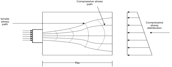
End blocks of post tensioned beam:- idealized stress paths
- The effect of transverse tensile stress is to develop a zone of bursting tension in a direction perpendicular to the anchorage force, resulting in horizontal cracking as shown in figure below
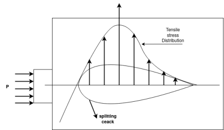
End blocks of post tensioned beams:- bursting tension and spitting cracks
- he distribution of transverse stresses in the anchorage zone subjected to a symmetrically placed prestressing force, which is distributed over a small area for
- increasing ratio of  varying from zero to 0.5 has been investigated by Guyon.
Bursting tensile force[IS 1343-2012, Clause no. 19.6.2.2, pp-26]
a) The bursting tensile forces in the end blocks, or reasons of bonded post tensioned members should be assessed on the basis of the tendon jacking load. For unbonded members, the bursting tensile forces should be assessed on the basis of the tendon jacking load or the load in the tendon at the limit state of collapse, whichever is greater.
The bursting tensile force,  existing in an individual square and block loaded by a symmetrically placed square anchorage or bearing plate, may be derived from the equation below:

Where,
 bursting tensile force
 load in the tendon assessed as above
 side of loaded area
 side of end block
b)The force  will be distributed in a region extending from
  from the loaded face of the end block. Reinforcement provided to sustain the bursting tensile force may be assumed to be acting at its design strength (0.87 times characteristic strength of R/F) except that the stress should be limited to a value corresponding to strain of 0.01 when the concrete cover to the R/F is less than 50 mm.
c)when circular anchorage or bearing plates are used, the sides of the equivalent square area should be used. Where groups of anchorages or bearing plates occur, the and blocks should be divided into a series of symmetrically loaded prisms and each prism treated in the above manner. For designing and blocks having a c/s of the beam, reference should be made to specialist literature.
Mechanism of prestress transfer and transmission length [IS 1343-2012, Clause no. 19.6.1, pp-26]
Mechanism of transfer of prestress:-
- Pre tensioned members are not provided with anchorage devices at the ends. The stretch tendons transfer the prestress to the concrete leading to a self equilibrium system.
- The prestress is pre tensioned member is transferred by the bond between concrete and the tendons.
- There are three mechanisms in the bond
1) Adhesion between concrete and steel.
2) Mechanical bond at the concrete and steel interface.
3) Friction in presence of transverse compression.
- The mechanical bond is the primary mechanism in the bond for intended wires, twisted stands and deformed bars. The surface deformation and ensures the bond between steel and concrete.
Transmission length:-The prestress is transferred over a certain length from each end of a member, which is called as transmission length.
- The stress in tendon is zero at the end of the members. It increases over the transmission length to the effective prestress under services load and remains constant beyond it.
- Transmission length needs to be calculated to check the adequacy of prestress in the tendon over the length. A section with high movement should be outside the transmission length, so that tendon retains at least the design effective prestress at the section.
Transmission length depend upon several factors:-
1) Types of tendon such as wire, strand or bar.
2) Size of tendon.
3) Stress in tendon.
4) Surface deformations on the tendon such as:- plain, indented, twisted or deformed tendons.
5) Strength of concrete at transfer.
6) Pace of cutting tendon like- abrupt flame cutting or slow release of Jack.
7) Effect of creep.
8) Compaction of concrete.
9) Concrete cover.
10) Presence of confining reinforcement
Problem no. 01:-The end block of bonded post tensioned P.S.C. Beam 300mm×300mm is a subjected to a concentric anchorage force of 800KNby cables passing through four ducts each of size 20mm diameter. The ducts are placed symmetrically.
Design the end block take strength of concrete at transfer as  and jacking force as 950 KN.
Given data:-b=300mm ; D=300mm ; anchorage force 
Four ducts ; each duct size=20mm; strength of concrete at transfer 
Jacking force=950KN
Design the end block
Solution:-
1) Calculate anchor plate size :- 
Assume  (Which less than 0.8fci = 0.8x 30 =24 N/mm²)
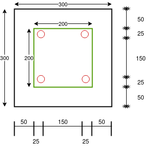

Assume Square plate 
2) Check for bearing stress


=
 or
or  whichever is less

Actual bearing stress =
Hence safe in bearing
3) Calculate bursting tensile force

Where;


4) Calculate area of stirrups required

Use 8mm 
Number of stirrups=
Problem no. 02:-A bonded post tensioned PSCbeam of size 400 mm wide and 1000mm deep is subjected to two symmetric cables, each with 1600 KN transfer prestressing force. Anchorage plates of size 250mm×350mm are used to fix the cables. Duct for each cable is of size 45mm ×45mm as shown in figure. Check the bearing stress and design the stirrups
Given
1) Strength in concrete at transfer=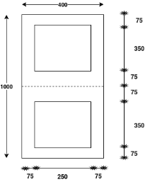

2) Load is jacks while stressing=1800 KN
3) Steel for stirrups Fe-415
Solution:-
1) Area of punching 
=(250×350)-(45×45)

2) Actual bearing stress (
=

3) Area of bearing=(400)×(75+350+75)

4) Permissible bearing stress


 or
or 
Whichever is less

5) Calculate bursting tensile force

Where;

Which ever is less


1) Calculate area of stirrups required

Use 8mm 
Number of stirrups=
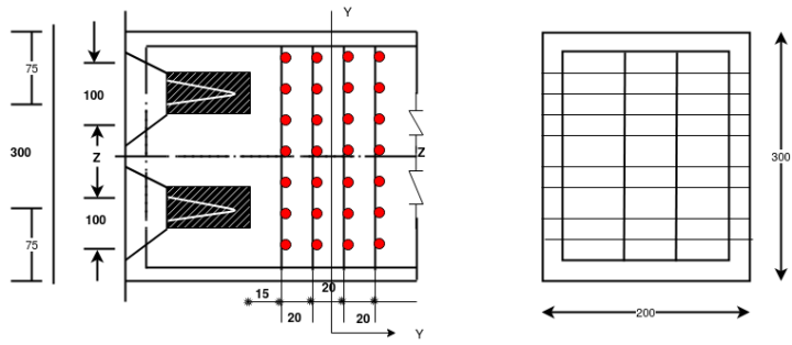
Problem no. 03:-The end block of a prestressed concrete girder is 200mm wide and 300mm deep. The beam is post tensioned by two freyssient anchorages each of 100mm diameter with their centres located at 75mm from the top and bottom of the beam the force transmitted by each anchorage being 200°KN. Compute the bursting force and design suitable reinforcements according to the IS-1343 provisions:
Given data:-b=200mm ; D=300mm ; Anchorages diameter=100mm

Calculate bursting force
We know that,
Bursting tensile force [IS 1343-2012,clause no 19.6.2.2, pp-27]

Where;
 load on tendon=2000KN
 side of loaded area=
Equivalent side of the square=
 side of end block=
 =2×75=150mm
1 =>
Using 10 mm diameter mild steel links with yield stress of 260
Number of bars required
The reinforcement is arranged in the zone between 0.240 and 40. Therefore 0.240=0.2×75=15mm and  16 no.s of 10 mm - diameter bars are arranged at a spacing of 40mm in front of the anchorage both in the longitudinal and transverse directions as shown in figure below
Problem no. 04:-The end block of a post tensioned prestressed member is 550mm wide and 550mm deep. Four cables each made up of seven wires of 12 mm diameter strands and carrying a force of 1000KN , are anchored by plate anchorage 150mm by 150mm located with their centres at 125 mm from the edges of the end block. The cable duct is of 50 mm diameter. The 28 day cube strength of concrete  is 25
is 25  permissible bearing stresses behind anchorages should confirm with IS-1343 the characteristic yield stress in mild steel anchorage reinforcement is 260
  design suitable anchorages for the end block.
Given data:- b=550mm ; D=550mm ; strands=12mm by 7 wires  tendon force=1000KN ; anchorages plate size=150×150mm,cable duct=50mm area of cable duct=
 ;
;  ; design suitable anchorages end block
Solution:-

Net area of surrounding prism =  area of cable duct


Average compressive stress 
According to IS-1343-2012 196.21 ; PP-26 the bearing stress shall not exceed

Whichever is smaller
Where,


Bearing stress limited to

Or 

Actual bearing stress=19.68 
We know bursting tension 19.6.22 PP-27


Using 10 mm diameter HYSD links

Number of bars=
Provide 8 bars of 10 mm diameter
Problem no. 05:-The end block of a post tensioned beam is 80 mm wide and 160 mm deep. A prestressing wire, 7mm inner diameter, stressed to 1200  has to be anchored against the end block at the centre. The anchorage plate is 50 mm by 50 mm. The wire bears on the plate through a female cone of 20mm diameter. Given the permissible stress in concrete at transfer,
  and the permissible shear in steel as 94.50
  determine the thickness of the anchorage plate.
Solution:-b=80mm ;D=160mm ; wire=7mm.  anchorage plate size=(50×50) mm ; female cone wire=20mmØ. ;
  permissible shear in steel=94.50
Calculate thickness of plate =?
Solution:-area of single wire= 

P=σA =1200×38.48=46.176× =46.176 KN


Average stress 
Permissible bearing pressure shall not exceed

Whichever is smaller


Bearing stress

Or 

Female cone diameter=20mm ; punching circumference=πd=π×20=62.84mm
If ; t=thickness of anchorage plate
Circumference× permissible shear ×tk=force on wire
62.84×94.50×t=46.176×
t=7.77mm ≈8mm
Use an anchorage plate of 8mm thickness
Problem no. 06:-The end block of a post tensioned continuous girder of span 40mm is 800 mm wide and mm mm deep. The preyssientanchoragess used for the stands has plates of size 340 mm by 340 mm. Each of the three strands carry a force of 4000KN and the three encourage plates are spaced at intervals 500mm along the depth of the end block. Design suitable and anchorage reinforcement for the end block using Fe-415 HYSD bars according to IS: 1343 code specifications.
Given data:-span=L=40m b=340mm d=2000mm 

We know that, bursting force 


Using Fe-415 HYSD bars, area of steel required is computed as

Classification of slab
1) One way slab
2) Two way slab
One way slab:-The design of prestressed concrete one way slab spanning between parallel supports is based on the principles of designing members for flexure(design of beam)
- One way slabs may be supported across the entire width of The slap by beams, piers or abutments or bearing walls, which are positioned perpendicular to the longitudinal axis of the span, or the supports may be at an angle to the span directions. One way slabs may be continuous over one or several supports.
- Simple or continuous slabs are analysed for design moments by considering a unit width of the slab.
- The prestressing force and the eccentricity of the cable required at prominent sections to resist the dead and live load moments are determined and the spacing of the cables or wires is fixed based on the availability of the types of tendons.
- In the case of slabs subjected to heavy concentrated loads, transverse reinforcement in the form of mild steel or deformed bars or prestressed cables will be required to resist transverse moments.
- Concentric tendons are generally preferred for transverse prestressing of one way slabs to prevent objectionable deflections in the transverse direction.
- The slabs designed should conform to the requirements of serviceability and strength.
- The serviceability requirements include limiting deflection and cracking under working loads as prescribed in the codes.
Problem no.01:-A simply supported one way post tensioned slab is spanning over 10m. The slab is required to support a live load of 10 If
If  and compressive stresses are not likely to increase in service conditions and structure is type 1, determine minimum depth of slab required. Ek loss ratio as 0.80 & the case strength of concrete at transfer as 23Mpa. [SPPU-ISE-2017]
Given data:-span=L=10m ; live load=wg=q=10 ; K=0.80
  at service and
  at transfer
Step 1 calculate bending moment
a) Due to live load 

b) Due to dead load:-
Self weight of slab= bdr=1×d×25=25d 

Step 2 calculate slab depth
a) For live load
We know,
d=158.11 ≈160mm
b) For Dead load
Similarly


d=210mm
Problem no.02:- A Highway bridge deck slab spanning 10 M is to be designed as a one way prestressed concrete slab with parallel post tensioned cables carrying an effective force of 620KN. The deck slab is required to support a UDL of live load of 25  .The permissible stresses in concrete should not exceed 15
  in compression and no tension is permitted at any stage. Design the spacing of the cables and their position at midspan section. Assume loss of prestress as 20%
Given data:-span of the deck slab=10m
Distributed working live load 
Force in cable 
Permissible compressive stress in concrete=
Permissible tensile stress in concrete= 
Loss of prestress 20% =n=0.80
Step 1 calculate bending moment
a) Due to live load q= 25 

b) Due to dead load
Dead load intensity g=area×unit weight of concrete

b=width of slab
h=overall depth of slab


Step 2 calculate thickness of slab
1) Range of stress at bottom fibre=


=
Hence, the minimum section modulus is given by the expression


h=410.55mm ≈410mm
Thickness of slab=410mm
Step 3 calculate prestress in concrete
a) Area=b.h
b) Section modulus=
c) Dead load moment 
d) Final stress
At top 
At bottom 

Step 4 calculate prestressing force


Step-5 calculate eccentricity e


Step 6 calculate spacing of cable
Spacing

Adopt spacing of 200mm centres for the cables in the span directions.
Problem no.03:-The floor slab of an industrial structure, spanning over it is to be designed as a one-way prestressed concrete slab with parallel post tensioned cables. The slab is required to support a live load of 10  with the compressive and tensile stress in concrete at any stage not exceeding 14 and 0
  respectively. Design a suitable thickness for the slab and estimate the maximum horizontal spacing of the preyssient cables (12 of 5mm diameter initially stressed to 1200
  and their position at mid span section. The loss ratio is 0.8
Given data:-span of slab=8m
Live load 
Force in cable 
Permissible compressive stress in concrete=
Permissible tensile stress in concrete= 
Loss of prestress 20% =n=0.80
Loss ratio=0.8
Solution:-
Step 1 calculate bending moment
a) Due to live load q= 10

b) Due to dead load
Dead load intensity g=area×unit weight of concrete

b=width of slab
h=overall depth of slab


Step 2 calculate thickness of slab
1) Range of stress at bottom fibre=


Hence, the minimum section modulus is given by the expression


h=200mm
Thickness of slab=200mm
Step 3 calculate prestress in concrete
a) Area=b.h
b) Section modulus=
c) Dead load moment 
d) Final stress
At top 
At bottom 

Step 4 calculate prestressing force


Step-5 calculate eccentricity e


Step 6 calculate spacing of cable
Spacing

Adopt spacing of 190mm centres for the cables in the span directions.
Problem no.04:-A post tensioned prestressed rectangular beam of span 15m is a subjected to an imposed UDL= . The stresses in concrete should not exceed 16.50
  in compression and 1.10
  in tension. The loss of prestress is 15%. Calculate the minimum possible depth and also find minimum prestressing force and the corresponding eccentricity. The width of the beam is to be taken as 300 mm. [SPPU-ESE-2016]
Given data:-
Span=L=15m
Live load=
Dead W=25 


n=7
Loss ratio=15%=0.85
Solution:-
Step 1 calculate bending moment
c) Due to live load q= 10

d) Due to dead load
Dead load intensity g=area×unit weight of concrete

b=width of slab
h=overall depth of slab


Step 2 calculate thickness of slab
2) Range of stress at bottom fibre=


Hence, the minimum section modulus is given by the expression


h=630mm
Thickness of slab=630mm
Step 3 calculate prestress in concrete
a) Area=b.h
b) Section modulus=
c) Dead load moment 
d) Final stress
At top 
At bottom 
=-1.294+24.55
=23.25 
Step 4 calculate prestressing force


Step-5 calculate eccentricity e


Two way slab
The design of a two way slab supported on all four sides involves the computation of bending moments in the principal directions of the slab. The slabs may be supported on walls aur beams and major may not be continuous over the supports.
- Transverse loads are registered by the development of two way slab action, resulting in moments in the longer and shorter span directions.
- the magnitude and nature of movements developed into a slabs depend mainly upon the type of load, ratio of the sides of slab, and the degree of restraint at the supports.
- The moments developed in a two way slab may be determined by the elastic analysis, such as those of westergard and pigeaud or, alternatively by the ultimate load methods, such as Johnson's yield line method or Hillerbory's strip method.
- The bending moment coefficient shown in table 27 IS-456-2000 clause no. D-2.1 for the design of two way slabs, simply supported on all four sides without any adequate provision to resist torsion and the lifting of corners.
- Bending moment coefficient shown in table 26 IS-456 -2000 PP-91, are useful for the design of restrained slabs supported on four sides with provision for torsion add corners as provided in IS cafe as well as British cafes.
- these coefficients are based on the modified distributions of elastic pending moments proposed by westergard.
- It is also significant to note that efficient predicted by the simple yield line theory using an orthotropic layout of reinforcement are found to be identical with those derived by the strip method.
- The moment coefficient derived from the ultimate load methods are generally lower in magnitude than those evaluated from elastic theories does naturally resulting in savings in reinforcement.
- However, slabs designed by the ultimate load method should be checked for excessive deflections. And/ or crack width under service loads according to the principles of limit state design.
Slabs spanning in two directions

Restrained slabs


Where
 are coefficients given in table 26,
w=total design load per unit area
 =Moments on strips of unit width spanning
  respectively, and
 =length of the shorter span and longer span respectively
Table26:Bending Moment Coefficients for Rectangular Panels supported on Four sides with Provision for Trosion at corners
(cause D-1.1 and 24.4.1)

Types of Panels and short span coefficent αs long span
Moments considered (Values of Iy/Is) coefficient
For the αy Values
1.0 1.1 1.2 1.3 1.4 1.5 1.75 2.0 Iy/Is
(1) (2) (3) (4) (5) (6) (7) (8) (9) (10)
Interior Panels: Negative moment at continuous edge positive moment at mid span |
0.032
0.024 |
0.037
0.028 |
0.043
0.032 |
0.047
0.036 |
0.051
0.039 |
0.053
0.041 |
0.060
0.045 |
0.065
0.049 |
0.032
0.024 |
One short Edge Continuous: Negative moment at continuous edge positive moment at mid span. |
0.037 0.028
|
0.043 0.032 |
0.048 0.036 |
0.051 0.039 |
0.055 0.041 |
0.057 0.044 |
0.064 0.48 |
0.068 0.052 |
0.037 0.028 |
One long edge discontinuous: Negative moment at continuous edge positive moment at mid span. |
0.037 0.028 |
0.044 0.033 |
0.052 0.044 |
0.057 0.044 |
0.063 0.047 |
0.067 0.051 |
0.077 0.059 |
0.085 0.065 |
0.037 0.028 |
Two adjacent edges discontinuous : Negative moment at continuous edges positive moment at mid span. |
0.047 0.035 |
0.053 0.040 |
0.060 0.045 |
0.065 0.049 |
0.071 0.053 |
0.075 0.056 |
0.084 0.063 |
0.091 0.069 |
0.047 0.035 |
Two short edges discontinuous : Negative moment at continuous edge positive moment at mid span |
0.045 0.035 |
0.049 0.037 |
0.052 0.040 |
0.056 0.043 |
0.059 0.044 |
0.060 0.045 |
0.065 0.049 |
0.069 0.052 |
- 0.035 |
Two long edges discontinuous: Negative moment at continuous edge positive moment at mid span. |
- 0.035 |
- 0.043 |
- 0.051 |
- 0.057 |
- 0.063 |
- 0.068 |
- 0.080 |
- 0.088 |
0.045 0.035 |
Three edges discontinuous (oneLong edge continuous) Negative moment at continuous edge positive moment at mid span. |
0.057 0.043 |
0.064 0.048 |
0.071 0.053 |
0.076 0.057 |
0.080 0.060 |
0.084 0.064 |
0.091 0.069 |
0.097 0.073 |
- 0.043 |
Three edges discontinuous (one Short edge continuous) Negative moment at continuous edge positive moment at mid span. |
- 0.043 |
- 0.051 |
- 0.059 |
- 0.065 |
- 0.071 |
- 0.076 |
- 0.087 |
- 0.096 |
0.057 0.043 |
Four edges discontinuous : Positive moment at mid span. |
0.056 |
0.064 |
0.072 |
0.079 |
0.085 |
0.089 |
0.100 |
0.107 |
0.056 |
Moments for the unit width are given by the following equation:


Where Mx ,My ,w,lx,ly are same those in D-1.1 and 𝞪x and 𝞪y are moment coefficient given in table 27.
Table27:Bending Moment Coefficients for Slabs Spanning in Two Directions at Right Angles, Simply supported on Four sides
(cause D-2.1)
Iynx | 1.0 | 1.1 | 1.2 | 1.3 | 1.4 | 1.5 | 1.75 | 2.0 | 2.5 | 3.0 |
𝞪x | 0.062 | 0.074 | 0.084 | 0.093 | 0.099 | 0.104 | 0.113 | 0.118 | 0.122 | 0.124 |
𝞪y | 0.062 | 0.061 | 0.059 | 0.055 | 0.051 | 0.046 | 0.037 | 0.029 | 0.020 | 0.01 |
Problem No. 01:-Design a post tensioned prestressed concrete two way slab 6m×9m with continuous edges to support and imposed load of  cables of four wires of 5 mm diameter carrying an effective force of 100KN are available for use. Design the spacing of cables in the two directions and check for the safety of the slab against collapse and excessive deflection at service loads. Assume
Given data:-design two way slab

Live load on slab=
&
Force in each cable=100KN

Step 1 calculate thickness of slab

Two way slab
Thickness of slab =
h=120mm
Step 2 calculation of loading
1) Self weight of slab=0.12×1×24=2.88
2) Live load on slab. =3 
3) Floor finish load. =0.15 
Total=6.03
Step-3 Calculate B.M. Coefficient & BM and spacing
As per IS-456-2000 clause no. 24.4 & D-1.1 PP-91 table-26
As four edges discontinuous


For Span LxFor Span Ly
The moment in the middle strip (x-direction)=
=130.41KNM
Using a minimum cover of 30mm for the tendons at the centre of slab, the distance between the top kern and the centeroid of cable
E=120-40-30=50mm
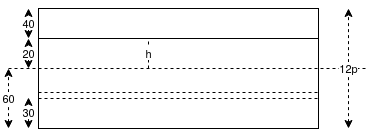
We know M=P.e
If P=Total prestressing force required in the x-direction


Force in each cable=100KN
a) No. Of cables in x-direction (middle strip)= say 26 No.s
b) Spacing of cables=
=260mm
By practical point of view adopt a spacing of 250mm(four cables per metre)
B] The moment in the middle strip (y-direction) =
Using a minimum cover of 40mm for the tendons at the centre of slab, the distance
E=120-40-40=40mm
If P=total prestressing force required in the y-direction
M=P.e =>


Force in each cable=100KN
a) No. Of cables in y-direction (middle strip) =
b) Spacing of cables=
=320mm
The cable profile is parabolic with maximum eccentricity at the center and concentric at the supports.
Step-4 Check for limit state collapse
1) Ultimate moment in x-direction =


 Area of prestressing force
No. Of cable in x-direction per metre span=

Calculate moment of resistance (as per D-1 PP-51)


 From table 11 PP-51 IS-1342-2012


The ultimate moment capacity of the slab is higher than the minimum value required . A similar check may be made in the y-direction also .
Check for deflection under service loats (perm)
The tendons following a paralotic profile in x and y direction induces uniformly distributed loads acting upward , which are given by
- Equivalent load (x-direction)=


2) Equivalent load (y-direction) 
No. Of cable=


3) Unbalanced service load=6.03-2.67-0.62=2.72KN/m

We know 
Where
α=0.00772
 using direction coefficients


D= flexural rigidity=


=4.83mm
Maximum permissible long term deflection=
Step-6> Check for stresses
1) Unbalanced load=2.72
Moment due to this load (x-direction) =

M=8.71KN.M
2) Bending stress σ=M/Z


(compression at top and tension at shaft of slab)
Direct stress due to prestressing force =P/A=
Final stress
Maximum compressive stress in concrete at the top of slab

The maximum shear stress under ultimate loads is

Which is negligibly small and hence the shear reinforcement are necessary
Problem No. 02:-Design a post-tensioned prestressed concrete two-way slab,5m by 8.5mm in size to support a live load of 4 KN/ . If cables of four wires of 5mm diameter stressed to 1100
 are available for use,determine the number of cable in the two principal directions the stresses in concrete not to exceed 15
 in compression and tensile stresses are not permitted under service loads. The loss ratio is 0.75. Check for the limit states of serviceability and collapse
Given data:-Design a post tensioned prestressed concrete two way slab.

Live load on slab=
&
Force in each cable=86.38KN

Step 1 calculate thickness of slab

Two way slab
Thickness of slab =
h=100mm
Step 2 calculation of loading
1) Self weight of slab=0.10×1×24=2.4
2) Live load on slab. =4 
3) Floor finish load. =0.12 
Total=6.52
Step-3 Calculate B.M. Coefficient & BM and spacing
As per IS-456-2000 clause no. 24.4 & D-1.1 PP-91 table-26
As four edges discontinuous


For Span LxFor Span Ly
The moment in the middle strip (x-direction)=
=103.91KNM
Using a minimum cover of 300mm for the tendons at the centre of slab, the distance between the top kern and the centeroid of cable
E=100-32-30
=38mm
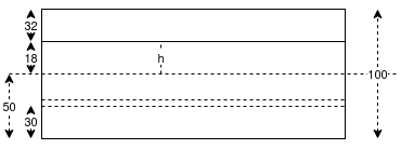
We know M=P.e
If P=Total prestressing force required in the x-direction

Force in each cable=86.38KN
c) No. Of cables in x-direction (middle strip)= say 32 No.s
d) Spacing of cables=
=200mm
By practical point of view adopt a spacing of 200mm(four cables per metre)
The moment in the middle strip (y-direction) =
Using a minimum cover of 40mm for the tendons at the centre of slab, the distance
e=100-32-40=28mm
If ,P=total prestressing force required in the y-direction
M=P.e =>


Force in each cable=86.38KN
c) No. Of cables in y-direction (middle strip) =
d) Spacing of cables=
=250mm
The cable profile is parabolic with maximum eccentricity at the center and concentric at the supports.
Problem No. 03:-A simply supported post tensioned slab, 500mm thick has span of 10m the slab is prestressed by cables each containing 12 high tensile wires of 8mm diameter. The cables are spaced at 500mm c/c at an effective depth of 450mm. Estimate the ultimate flexural strength of the slab. Also determine the maximum permissible uniformaly distributed ultimate live load that can be placed on slab assuming. Consider load factors for live load and dead load as 1.5 Take  and
and  [SPPU-ISE-2017]
Given data:-Given data as shown in figure
 D=500mm

Spacing=500mm c/c
d=450mm :
Solution:-
1) We know that, effective R/F ratio( use pp-51)


2) Moment of resistance for flexure


=

3) To find L.L. Equate above moment to moment due


Problem No. 04:-Design a two way slab of size 7.5m supported on four beams and discontinuous over one long edge. The slab supports a live load
  . Use 6.3mm -7 ply strands having a nominal cross sectional area of 25.10
  The breaking load of the strand may be taken as 44.48KN. The loss coefficient is 0.85
Given data:-Design a two way slab 
End condition:- Discontinuous over one long edge
Live load=
Force in strands=44.48KN : Loss coefficient =0.85
Step 1 calculate thickness of slab

Two way slab
Thickness of slab =
h=150mm
Step 2 calculation of loading
1) Self weight of slab=0.15×1×24=3.6
2) Live load on slab. =5 
3) Floor finish load. =0.15 
Total=8.75
Step-3 Calculate B.M. Coefficient & BM and spacing
As per IS-456-2000 clause no. 24.4 & D-1.1 PP-91 table-26

A) Short span coefficient
Negative moments
1.3 | 0.057 |
1.34 | X |
1.4 | 0.063 |

Positive moments
1.3 | 0.044 |
1.34 | Y |
1.4 | 0.047 |

Negative short span coefficient= 0.0594
Positive short span coefficient= 0.0452


a) The moment in the middle strip(x-direction) 
Using a minimum cover of 30mm for the tendons at the centre of slab, the distance between the top kern and the centeroid of cable


We know M=P.e
If , P=Total prestressing force required in the x-direction

Force in each cable=44.48KN
a) No. Of cables in x-direction (middle strip)= say 54 No.s
b) Spacing of cables=
=140mm
By practical point of view adopt a spacing of 140mm(four cables per metre)
The moment in the middle strip (y-direction) =
Using a minimum cover of 40mm for the tendons at the centre of slab, the distance


M=P.e =>

P=1291.83KN
Force in each cable=44.48KN
a) No. Of cables in x-direction (middle strip)= say 29 No.s
b) Spacing of cables=
=195mm
Problem No. 05:-A post tensioned simply supported prestressed concrete isolated two way slab of  with discontinuous edges supports an imposed load
  , Use M-45 grade of concrete and 3P/4=3mm strands with a stress of 1300MPa check the safety of the slab against collapse and direction at ultimate load.
Given Data:-Design a two way slab 
Live load =imposed load=4 ;
; 
Step 1 calculate thickness of slab

Two way slab
Thickness of slab =
h=130mm
Step 2 calculation of loading
4) Self weight of slab=0.130×1×24=3.12
5) Live load on slab. =4.00
6) Floor finish load. =0.15 
Total=7.27
Step-3 Calculate B.M. Coefficient & BM and spacing
As per IS-456-2000 clause no. 24.4 & D-1.1 PP-91 table-26
As four edges discontinuous
1.3 | 0.072 |
1.38 | X |
1.4 | 0.085 |


The moment in the middle strip (x-direction)=
=170.775KNM
Using a minimum cover of 300mm for the tendons at the centre of slab, the distance between the top kern and the centeroid of cable
E=130-30-40=60mm
Prestressing force P=Area of strands

=40.29KN
Initial prestressing is prestressing force required in x- direction

Force in each stand=40.29KN
e) No. Of cables in x-direction (middle strip)= say 71 No.s
f) Spacing of cables=
=95mm
The moment in the middle strip (y-direction)=
=83.85KNM
Using a minimum cover of 40mm for the tendons at the centre of slab, the distance between the top kern and the centeroid of cable
E=130-40-40=50mm
If P=total prestressing force required in the y direction

Force in each stand=40.29KN
a) No. Of cables in y-direction (middle strip)= say 42 No.s
b) Spacing of stand=
Spacing=115mm