UNIT 3
Design of Flat Slab
The common practice of design and construction is to support the slabs by beams and support the beams by columns. This may be called as beam slab construction.
The beams reduce the available net clear ceiling height. Hence in warehouses, offices, and public halls sometimes beams are avoided, and slabs are directly supported by columns. This type of construction is aesthetically appealing also. Theseslabs which are directly supported by columns are called flat slabs.
Figure a shows a typical flat slab.
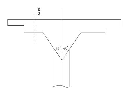
The column head is sometimes widened to reduce the punching shear in the slab. The widenedportions are called column heads. The column heads may be provided with an angle from the consideration of architecture but for the design, concrete in the portion at 45° on either side of vertical-only is considered as effective.
Moments in the slab are more near the column. Hence the slab is thickened near the columns by providing the drops as shown in the figure below.
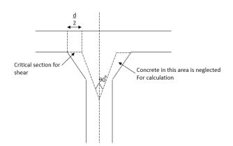
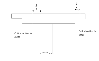
Fig. C slab with a drop, and column without column head
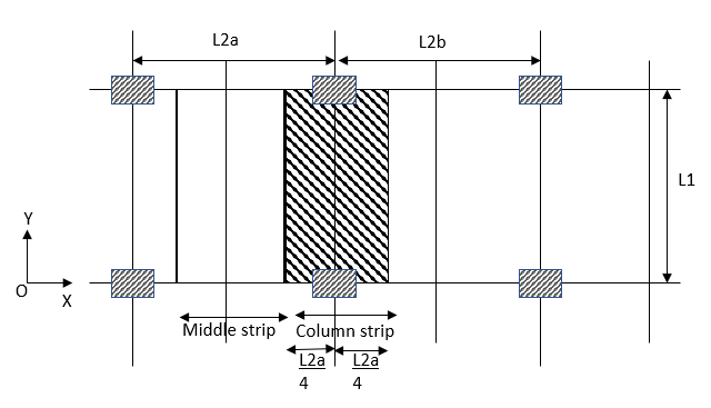
The portion of a flat slab that is bound on each of its four sides by centerlines of adjacent columns is called a panel. The panel is shown in the figure as shown in the figure. Size  A panel may be divided into column strips and middle strips. Column strip means a design strip having a width of 0.25
  or 0.25
 whichever is less. The remaining middle portion which is bound by the column strips is called the middle strip below figure shows the division of flat slab panel in two-column and middle strips in the direction y.
Proportioning of flat slab
IS 456-2000 [Clause no 31.2, Pp-53]gives the following guidelines for proportioning.
Drops:-The drops when provided shall be rectangular in plan, and have a length in each direction not less than one-third of the panel in that direction. For exterior panels, the width of drops at right angles to the non-continuous the edge, and measured from the centerline of the column shall be equal to one half of the width of drop for interior panels.
Column heads:-Where column heads are provided that portion of the column head which lies within the largest right circular cone for pyramid entirely within the outlines of the column, and the column head, shall be considered for design purpose as shown in the figure.
The thickness of flat slab:-From the consideration of deflection control IS 456-2000 specifies minimum The thickness in terms of span to effective depth ratio. For this purpose,the largest span is to be considered. If you drop as specified in A is provided, then the maximum value of the ratio of the largest span to The thickness shall be
=40 if mild steel is used
=32, if Fe-415 or Fe-500 steel is used
If drops are not provided or the size of drops does not satisfy the specification A then the ratio shall not exceed 0.9 times I.e.
=40×0.9=36, if mild steel is used
=32×0.9=28.80, if HYSD bars are used
It is also specified that in no case, The thickness of the flat slab shall be less than 125 mm
Determination of bending moment, and shear force
For this IS 456-2000 permits use of any one of the following two method
a) The direct design method
b) The equivalent frame method
The direct design method:-This method has the limitation that it can be used only if the following conditions are fulfilled.
- There shall be a minimum of three continuous spans in each direction.
- The panels shall be rectangular, and the ratio of the longer span to the shorter span within a panel shall not be greater than 2.
- The successive span length in each direction shall not differ by more than one-third of the longer span.
- The design live load shall not exceed three times the design dead load.
- The end span must be shorter but not greater than the interior span.
- It shall be permissible to offset columns a maximum of 10% of the span in the direction of the offsetting net withstanding the provision in II.
Total design moment:- [ IS 456-2000, clause no 31.4.2 pp-55]
The absolute sum of the positive, and negative movement in each direction is given by

Where,
 = total moment.
W=design load on the area 
 =clear span extending from face to face of columns, capitals, brackets or walls but not less than 0.65
 =length of span in the direction of
  , and
, and
 =length of span transverse to
In taking the values of  the following clauses are to be carefully noted.
a) Circular supports shall be treated as squares supports having the same area i.e. squares of size 0.886D
b) When the transverse span of the panel on either side of the centerline of support varies,  Shall be taken as the average of the transverse spans. In the figure, it is given by
c) When the span adjacent, and parallel to an the edge is being considered, the distance from the edge to the centerline of the panel shall be substituted for 
Distribution of bending moment into negative, and positive moments [IS 456-2000, clause no 31.4.3 pp-55]
a) In an interior span
- Negative design moment=0.65

- Positive design moment=0.35

b) In an, and span
1) Interior negative design moment=
2) Positive design moment=
3) Exterior negative design moment=
Where  is the ratio of flexural stiffness at the exterior columns to the flexural stiffness of the slab at a joint taken in the direction movements are being determined, and is given by,

Where,
 = sum of the flexural stiffness of the columns meeting at the joint, and
 = flexural stiffness of the slab expressed as moment per unit rotation.
Distribution of bending moments across the panel width [IS 456-2000, clause no 31.4.4 pp-55]
The positive and negative moments found are to be distributed across the column strip in a panel as shown in the table below. The movement in the middle stripe shall be the difference between the panel, and the column strip moments.
Table:- Distribution of moments across the panel width in a column strip
SR.NO. | Distributed moment | Percent of the total moment |
1 | Negative BM at the exterior support | 100 |
2 | Negative BM at the interior support | 75 |
3 | Positive bending moment | 60 |
Moments in columns:-
In this type of constructions, column moments are to be modified as suggested in IS-456-2000, clause no 31.4.5 pp-56
Shear force:-[IS-456-2000, clause no 31.6 pp-57]
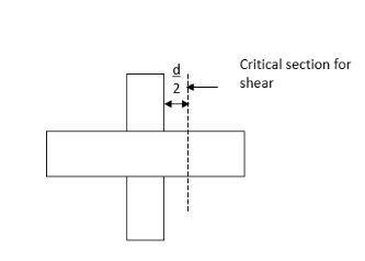
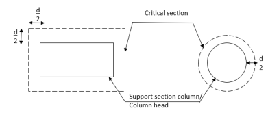
The critical section for a share shall be at a distance  from the periphery of the column/ capital drop panel. Hence if drops are provided there are two critical sections near columns. These critical sections are shown in fig a, and b. The shape of the critical section in the plan is similar to the support immediately below the slab as in the figure below.
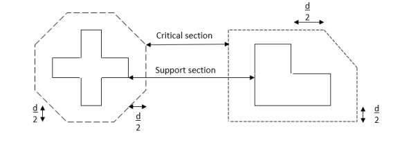
For columns section with reentrant angles is the critical section shall be taken as indicated in the figure below.
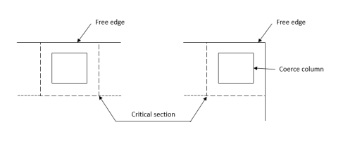
In the case of columns near the free the edge of a slab, the critical section shall be taken as shown in the figure.
The nominal shear stress may be calculated as
Where V=design shear force
 =the periphery of the critical section
d=the effective depth
The permissible shear stress in concrete be calculated as 
Where  but not greater than 1
 = The ratio of the short side to the long side of the column/capital; and

If shear stress no share reinforcement is required.
If shear reinforcement shall be provided. If share stress exceeds 1.5
 The flat slab shall be redesigned.
Equivalent frame method
IS 456-2000 requirements the analysis of flat slab, and column structure as a rigid frame to get design moment, and shear forces with the following assumptions:-
a) The beam portion of the frame is taken as equivalent to the moment of inertia of flat slab founded laterally by the center line of the panel on each side of the centerline of the column. In frames adjacent, and parallel to an the edge beam portion shall be equal to flat slab bounded by the edge, and the centerline of the adjacent panel.
b) Moment of inertia of the members of the frame may be taken as that of the cross-section of the concrete alone.
c) Variation of the moment of inertia along the axis of the slab on account of the provision of drops shall be taken into account. In the case of the recessed or coffered slab which is made solid in the region of the columns, the stiffening effect may be ignored provided the solid part of the slab does not extend more than 0.15 leff. into the span measured from the centerline of the columns, the stiffening effect of fluid columns heat may be ignored.
d) Analysis of frame may be carried out with a substitute frame method or any other accepted method like moment distribution or Matrix method.
Loading pattern
When the live load does not exceed3/4thof dead load, the maximum moments may be assumed to occur at all sections when full design live load is on the entire slab.
If the live load exceeds 3/4th that the lord analysis is to be carried out for the following pattern of the following also:-
a) To get maximum moment near midspan-3/4thof live load on the panel, and full live load on the alternate panel.
b) To get a maximum moment in the slab near the support-3/4th of the live load is on the adjacent panel only.
It is to be carefully noted that in no case design movement shall be taken to be less than those occurring with full design live load on all panels.
The moments determined in the beam or frame (Flat Slab ) may be reduced in such proportions that the numerical sum of positive, and average negative moments is not less than the value of total design moment  The distribution of slab moments in two-column strips and middle strips are to be made in the same manner as specified indirect design method.
Slab Reinforcement [IS 456-2000, clause no.31.7 pp-59]
a) Spacing:-the spacing of bars in a flat slab shall not exceed two times the slab thickness.
b) Area of reinforcement:-when the drop panels are used, The thickness of drop panel for determining the area of reinforcement shall be the lesser of the following
I) The thickness of drop, and
II) The thickness of the slab plus one-quarter the distance between the edge of the drop, andthe edge of the capital.
The minimum percentage of the reinforcement is the same as that in solid slab
i.e. 0.12% HYSD
0.15% MILD STEEL
c) Minimum length of reinforcement:-At least 50% of the bottom bar should be from support to support. The rest may be bent up the minimum length of different reinforcement in flat slab should be as shown[ IS 456-2000 fig.16]. If adjacent spans are not equal, the extension of the negative reinforcement beyond each face shall be based on the longer span. All slab reinforcement should be anchored properly at discontinuous edges.
Problem no 01 :-Design an interior panel of a flat slab of size 5m×5m without providing drop, and column head. Size of columns is 500×500mm, and live load on the panel is 4 Take floor fishing load as
  Use
Use  concrete, and Fe-415 steel.
Given data: Design, and interior panel of a flat slab
Size of flat slab=5m×5m ;
Size of columns=500×500mm
Live load on the panel is=4
Floor finishing load=


Step 1 calculate The thickness of slab: since the drop is not provided, and HYSD bars are use span to The thickness ratio shall not exceed 
Minimum The thickness required 
d=200mm
Step 2 Calculate loading:-
1) self-weight of slab=0.20×1×25=5
2) Live load =
3) Finishing load =1
Total working load=10
Factor load=1.5×10=15
 =5-0.5=4.5m
Therefore total design load in a panel W=15× =15×5×4.5=337.5KN
Step 3 Calculate moments
Panel moment 
In an interior span
Negative design moment=
Positive design moment=
Redistribution of moments
Distribution of moment into column strip, andthe middle strip
| Column strip in KNM | Middle strip in KNM |
Negative moment | 0.75×123.40=92.55 | (123.40-92.35) = 30.85 |
Positive moment | 0.60×66.44=39.86 | ( 66.44 – 39.86 ) = 26.58 |
Step 4 check for The thickness using Mulim
Since Fe 415 steel is used 
=0.138×20×2500×175²
=211.31×
=211.31KNM
b=width of column strip=0.5×5000
=2500mm
Hence singly reinforced section can be designed that is The thickness satisfactory from the consideration of bending moment.
Step 5 check for shear:-
The critical section for shear is at a distance d/2 from the column face. Hence periphery of the critical section around a column is square of a size=500+d
=500+175
=675mm
Shear to be resisted by the critical Section
V=15×5×5-15×0.675×0.675
=375-6.84=368.16KN
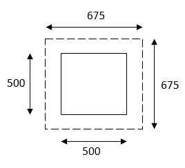
Nominal shear stress 
 subject to a maximum of 1.


Safe in shear, since 
Step 6 calculate reinforcement:-
a) For a negative moment in column strip:-
 =92.55KNM


Use 12mm  bars
bars
Spacing=
Hence provide 12mm bars @ 175mm c/c, provided in a column strip of width 2500mm.
b) For a positive moment in column strip:-


Use 10mm  bars
bars
Spacing=  < 2
< 2 thickness of slab
< 2 175=350mm
Hence provide 10mm bars 300mm c/c.
Provided in the middle strip to take up negative, and positive moments. Since span is the same in both directions, provide similar reinforcement in other directions also.
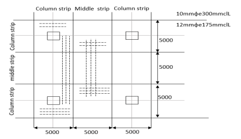
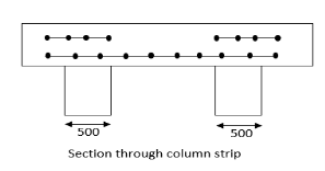
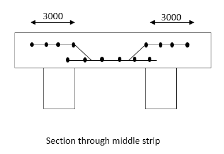
Problem No 02:-Design, andan interior panel of a flat slab with panel size 6×6m supported by columns of size 500mm×500mm. Provide suitable drop take the live load as  Use
Use  concrete, and Fe-415 steel.
Given data:-design, andan interior panel of a flat slab with a panel size of flat slab=6m×6m;
Size of column=500mm×500mm
Live load=
Step 1calculate The thickness of slab:-
Since Fe-415 steel is used, and drop is provided, the maximum span to The thickness ratio permitted is 32
ThereforeThe thickness of flat slab= =190mm
Provide 190mm The thickness. Let the cover be 30mm
D=d+ cover=190+30=220mm
OverallThe thickness D=220mm
Let the drop be 50mm
Hens at column head, d=190+50=240mm& D=d+30=240+30=270mm
Step 2calculatesthe size of drop:-it should not be less than 
Let us provide a 3m×3m drop so that the width of the drop is equal to that of the column header.
Therefore width of column strip=width of middle strip=3000mm
Step 3 load calculation:-
For design letters take the self weight as that due to The thickness at column strip.
Self weight=0.27×1×1×25=6.75
Finishing load=1.00
Live load
Total load=11.75 
Design load =1.5×11.75=17.625
Clearspan =6-0.5=5.5m
Design Load 
Step 4 calculate moments
Total moment 
In an interior span
Negative design moment=0.65 =0.65×400=260KNM
Positive design moment=0.35 =0.35×400=140KNM
Distribution of moment into columns strip, andthe middle strip
| Column strip in KNM | Middle strip in KNM |
Negative moment | 0.75×260=195 | 0.25×260=65KNM |
Positive moment | 0.60×140=84 | 0.40×140=56KNM |
Step 5 check for The thickness using 
Width of column strip=width of middle strip=3000mm
 =0.138
Mulim= 476.928>
Hence The thickness selected is sufficient.
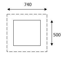
Step 6 check for shear:-The critical section for share is at a distance d/2 from the column face. Hence periphery of the critical section around a column is square of a size=500+d
=500+240
=740mm
Shear to be resisted by the critical section
V=total load-load on 0.74×0.74
=17.625×6×6-17.625×0.740×0.740
=624.84KN
Nominal shear stress
Shear strength=
Where  subject to a maximum of 1


Design shear stress permitted  ok
ok
Hence, the slab is safe in shear without shear reinforcement also shear strength may be checked at distance d/2 from a drop. It is quite safe since drop size is large.
Step 7 calculate reinforcement
a) For a negative moment in column strip


Use 12mm  bars
bars 
Spacing =
Hence, provide 12mm bars e 140mm c/c, provided in a column strip of width 3000mm.
b) For a positive moment in column strip


Use 12mm  bars
bars 
Spacing=
Hence ,provide 12mm bars e 140mm c/c,
c) For a negative moment in the middle strip


Use 12mm  bars
bars 
Spacing=
Hence,provide 12mm bars e 140mm c/c,
d) For a positive moment in the middle strip

Provide 10 mm bars at 240 mm c/c in this portion also.
Since span is same in both the direction, provided similar reinforcement in both directions. The details of reinforcement are shown in the figure.
Problem 03:- Design, andan interior panel of the flat slab with panel size 6×6m supported by columns head. If columns are of 500mm diameter. ( Use previous data)
Given data:-design, andan interior panel of a flat slab
Step 1) load calculation
1) Let the diameter of column head be=0.25L=0.25×6=1.5m
Its equivalent square has a site ‘a’ where,

Clearspan =6-1.33=4.67m
Design load=
Total moment 
In an interior span
Negative design moment=0.65  =0.65×288.28=187.382KNM
Positive design moment=0.35
Distribution of moment into column strip, andthe middle strip
| Column strip in KNM | Middle strip in KNM |
Negative moment | 0.75×187.382=140.53 | 0.25×187.382=46.34KNM |
Positive moment | 0.60×100.898=60.53 | 0.40×100.898=40.35KNM |
Step 4 check for The thickness using 
Width of column strip=width of middle strip=3000mm


Hence The thickness selected is sufficient
Step-5> Check for shear
The critical section is at a distance  from the face of the column header.
Diameter of critical section=1500+120+120=1740mm=1.74m
Perimeter of critical section=
Shear on this section V=

Nominal shear stress
Maximum shear permitted=


Since maximum shear permitted in concrete is more than nominal shear  there is no need to provide shear reinforcement
Step 6 calculate reinforcement
a) For a negative moment in column strip


Use 12mm  bars
bars 
Spacing =
Hence, provide 12mm bars @ 200mm c/c, provided in a column strip of width 3000mm.
b) For a positive moment in column strip
 mm
mm


Use 10mm  bars
bars 
Spacing=
Hence,provide 10mm bars @250mm c/c,
c) For a negative moment in the middle strip


Use 10mm  bars
bars 
Spacing=
Hence ,provide 10mm bars @300mm c/c,
d) For a positive moment in the middle strip


Use 10mm  bars
bars 
Spacing=
Hence, provide 10mm bars @ 390mm c/c,
Problem No 04:- A flat slab system consists of  panels, and is without a drop, and column head. It has to carry a live load of
  , and a finishing load of
  . It is to be designed using
  trade of concrete, and Fe-415 steel. The size of the columns supporting the system is 500
 , and floor to floor height is 4.5m. Calculate design moments in the interior, and exterior panels at the column, and middle strips in both directions.
Given data Size of flat slab= , Live load=
 FF=
FF= ,Size of column=500
 Height of column= 4.5m
Step-1) Calculate The thickness of slab:-Since Fe-415 steel is used, and drops are provided, longer span to depth ratio is not more than 

Step-2) Calculate Load
Self weight=0.24×1×1×25=6
Finishing load=1.00
Live load
Total load=11 
Factored (Design Load)
Step-3) Calculate panel dimensions
Along with length:-
Width of column strip= whichever is less
=0.25*6=1.5m
=0.25*5=1.25m
Total width of column strip=1.25*2*2.5m
Width of middle strip=5-2.5=2.5m
Along Width :-
Width of column strip= whichever is less
=0.25*6=1.5m
=0.25*5=1.25m
Total width of column strip=1.25*2*2.5m
Width of middle strip=6-2.5=3.5m
Interior Panels
1) Moment along longer size 
 subject to a minimum of

Load on panel 

Appropriation of moment
Total negative moment=0.65×311.95=202.77KNM
Total positive moment=311.95-202.77=109.18KNM
Moments in column strip, and middle strip are as shown below
| Column strip in KNM | Middle strip in KNM |
Negative moment | 0.75×202.75=152.07 | 202.77-152.07=50.70KNM |
Positive moment | 0.60×109.18=65.51 | 109.18-65.51=49.67KNM |
2) Moment along width

 subject to a minimum of

Load on panel 

Appropriation of moment
Total negative moment=0.65×250.59=162.88KNM
Total positive moment=250.59-162.88=87.71KNM
Moments in column strip, and middle strip are as shown below
| Column strip in KNM | Middle strip in KNM |
Negative moment | 0.75×162.38=122.16 | 0.25×162.88=40.72KNM |
Positive moment | 0.60×57.71=52.63 | 0.40×57.71=35.08KNM |
Introduction:Prestressed concrete flat slab construction gained great importance because of several reasons that yield in the economy. P.C. That slab construct without beans andprestressed in two perpendicular directions. Flat slab constructions have the adaptability for any type of building requirements, ease in formwork, casting of concrete, and prestressing operations.
The slab is analyzed as a one-way slab, and the total number of cases required to resist the movements in each of the two principal directions is determined the slab is finite into column strips and middle strips.
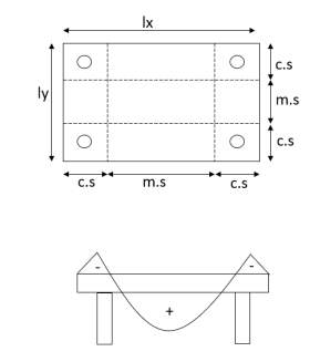
The column strips being stiffer than the middle strips, a greater percentage of the tendons are housed in the column strips. The proportion of tendon based on IS-456, where column strips share a higher proportion of the total moment. Since it is not generally possible to vary the spacing of cases for positive, and negative moments in either the column or the middle strips, the total number of cases required in any direction is apportioned in the ratio of 65, and 35% between the column, and middle strips.
Problem no 01:A simple flat slab 12m and 9m is supported by four columns to placed as to form a symmetrical rectangular grid, 7m×6m. The cantilever formed are 2.5m, and 1.5m in the long, and short directions of the slab. The live load on the slab is 1 Prestressing cables consisting of four wires of 5mm carrying on the effective force of 100KN are available for use. Design the number of cables required, and arrange them suitably in the two principal directions.
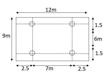
Given data: slab size (12×9)m
Given data shown in figure
Live load=1
Prestressing cable:- four wires of 5mm
Effective force 100KN
Calculate tendon/cable, and spacing
Solution:-
1) Calculate The thickness of the slab

2) Load calculation
Self-weight of slab=0.15×24×1=3.6
Live load on slab=1.0
Floor finish load=0.40
Total load=5.0
3) The total load on four column=Area×load intensity
=(12×9)×5
=540KNM
4) Load on each column=
The slab is analyzed for positive, and negative moments in the long span (X direction), and short span (y-direction)
5) Moments in the direction of long-span:-
a) The positive moment at the center of slab=

=135KNM
b) The negative moment at support=area× intensity ×C.G.
=(2.5×9)×5×
=140.625 KNM
The prestressing force required is designed to resist the maximum moment of 140.625KNM in the X-direction.
6) The cables are provided at a distance of 30mmfrom the edge of the slab at critical sections. The cable profile is parabolic along the span so that the centricity is proportional to the moment in the section.

7) The total prestressing force required in the X direction

8) Number of cables in X direction
9) In the x-direction, the width of the column, and middle strips are each 3m similarly in the short span the maximum moment occurs at the center of the slab, and equal to

=(270 3)-(270
 2.25)
2.25)

Eccentricity e=70mm
The total prestressing force required in the y-direction

Number of cables in wind direction
The column and middle strips are 7m, and 5m width in the Y direction. The total number of cases in each direction is distributed so that 65% are column strip, and 35% are in the middle strip.
The number of cables in X, and Y direction
| Column Strip | Middle Strip |
Direction | No. Of cables | No. Of cable |
X |  |  |
Y |  |  |
Problem No 02:A simple flat slab 10m by 8m is supported by four columns to placed as to form a symmetrical rectangular grid, 8m×6m. The cantilever formed of 1m, and 1.5m in the long, and short directions of the slab. The live load on the slab is 1.5 Prestressing cables consisting of four wires of 4mm carrying on the effective force of 1000
 are available for use. Design the number of cables required, and arrange them suitably in the two principal directions.
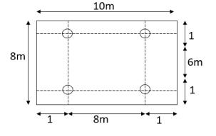
Given data: slab size (10×8)m
Given data shown in figure
Live load=1.5
Prestressing cable:- four wires of 4mm
Effective force 100KN
Solution:-
1) Calculate The thickness of the slab

2) Load calculation
Self-weight of slab=0.15×24×1=3.6
Live load on slab=1.5
Floor finish load=0.9
Total load=6.0
3) The total load on four column=Area×load intensity
=(10×8)×6
=480KNM
4) Load on each column=
The slab is analyzed for positive, and negative moments in the long span (X direction), and short span (y-direction)
5) Moments in the direction of long-span:-
a) The positive moment at the center of slab=

=240KN.M
b) Negative movement at support=area× intensity×C.G.
=(1×8)×6×
=24 KN.M
The prestressing force required is designed to resist the maximum moment of 240KNM in the X-direction.
6) The cables are provided at a distance of 30mm from the edge of the slab at critical sections. The cable profile is parabolic along the span so that the centricity is proportional to the moment in the section.

7) The total prestressing force required in the X direction

8) Number of cables in X direction
Force in each cable=

9) In the x-direction, the width of the column, and middle strips are each 3m similarly in the short span the maximum moment occurs at the center of the slab, and equal to

=(240 3)-(240
 2)
2)

Eccentricity e=70mm
The total prestressing force required in the y-direction

Number of cables in wind direction
The column and middle strips are 8m, and 6m width in the Y direction. The total number of cases in each direction is distributed so that 65% are column strip, and 35% are in the middle strip.
The number of cables in X, and Y direction
| Column Strip | Middle Strip |
Direction | No. Of cables | No. Of cable |
X |  |  |
Y |  |  |
Reference Books:
1) Deisgn of Prestressed Concrete structures-T.Y.Lin
2) Prestressed Concrete_N. Krishna Raju-Tata Mc Graw Hill Publication Co.
3) Prestressed Concrete_S.S. Bhavikatti-Medtech –A Division of Scientific International Engaging Sciences- Developing Minds.
4) Prestressed Concrete_K.U.Muthu ,etl.-PHI Learning Private Limited
5) Prestressed Concrete_S.Rmamrutham-Dhanpat Rai Publishing Company
6) Prestressed Concrete_P.Dayaratnam and P. Sarahi-Medtech –A Division of Scientific International Engaging Sciences- Developing Minds.
7) Prestressed Concrete( Analysis and Design Practice of Members)_Karuna Moy Ghosh -PHI Learning Private Limited
8) Prestressed Concrete- A Fundamental Approach-Edward Nawy-PHI