UNIT 4
Earth Retaining Structures
In order to retain earth in filling having a greater height, retaining walls are constructed. The retaining walls are usually preferred in following construction:
(1) Rail and road projects where earth filling is required.
(2) If basements are provided in buildings.
(3) Wing walls and abutments act as retaining walls.
There are following types of retaining walls:
(1) Cantilever or T-shaped retaining wall
(2) Counterfort retaining wall
(3) Buttress retaining walls
The cantilever walls may prove to be uneconomical if the retaining wall’s height is more than a certain limit. In order to achieve economy, counterfort retaining walls are provided.
These retaining walls are vertical beams which are connected to the stem as well as heel slab by reinforcement.
The design of heel slab and vertical stem may be treated as a continuous slab and not as a cantilever slab.
If the toe side is provided with the counterforts, the retaining wall is known as buttress wall.
Cantilever, counterfort and buttress retaining walls are shown in Figs. 3.1 and 3.2.
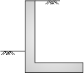
(a) Cantilever retaining wall without toe projection
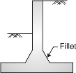
(b) Cantilever retaining wall with fillets
Fig. 4.1
(a) Counterfort Retaining Wall :
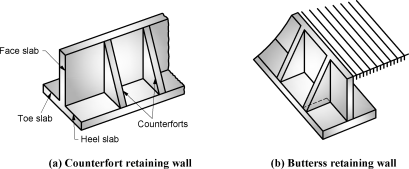
Fig. 4.2
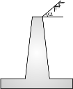
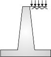
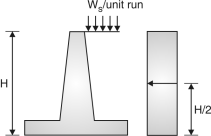
If a wall retains the earth level upto the top of retaining wall, it is known as retaining wall without surcharge.
If the earth on the retained side is not level or the earth carries load, the earth is said to have surcharge.
In this case, the pressure exerted by earth on wall is more.
|
|
|
Positive surcharge of sloping earth | Positive surcharge per Unit run | Negative surcharge of sloping earth |
Fig. 4.3
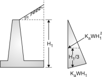
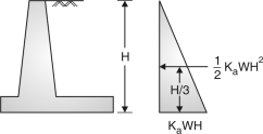
Fig. 4.4 Fig. 4.5
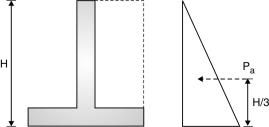
- Active earth pressure is defined as horizontal pressure exerted by retained earth on retaining wall.
- Passive earth pressure is defined as the resisting pressure applied by wall on the retained earth.
- The variation of this earth pressure is linear along the depth of retained earth.
- The total earth pressure upto the depth H (Fig. 3.4) is the area of pressure diagram which is 1/2 KaWH2 and acts at a height of H/3 from bottom. Hence, moment due to horizontal pressure = KawH3 ...(1)
Where Ka = and is the angle of repose of soil.
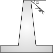
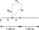
 In case of a sloping surcharge at an angle
to the horizontal pressure at a depth of
H1 due to earth= Ka WH1 and total earth
Pressure upto a depth of H1 = KaW
Which acts at a height of H1/3 and parallel
To the ground surface.
Moment about the base= KaWcos …(2)
Where, Ka = cos Fig. 4.6
- If the earth has a level surcharge of ws/unit run, then pressure at all depths is some of magnitude KaWs and the surcharge pressure at depth H is KaWs H acting at H/2 from bottom (Fig. 3.6)
Moment due to this at bottom =KaWH2 …(3)
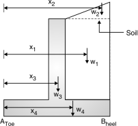
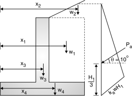
- The components of cantilever retaining wall are shown in Fig. 4.7.
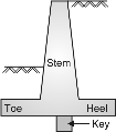 Stem is designed as a cantilever retaining earth.
- The toe and heel slabs are also designed as
Cantilevers resisting upward soil pressure and
Downward earth pressure.
- The retaining wall is provided with or without
Shear key at the bottom of the base slab to protect
The wall against sliding.
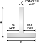
4.5.1 The general guidelines to decide the preliminary dimensions of the retaining wall:
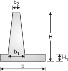 Following guidelines should be adopted while deciding the dimensions of a cantilever retaining wall:
(1) Top width of stem, b2= 200 mm
(2) Bottom width – Design for the maximum bending moment.
(3) Height of retaining wall = H
(4) Width of base slab = b
(5) b is usually kept between 0.5H to 0.6 H for walls
Without surcharge and 0.7H for walls with surcharge.
(6) Toe projection = b/3
Fig. 4.8
(7) The thickness of base slab is normally kept as same as the bottom width of
Stem i.e. b1 =H1
(8) The wall is to be checked for horizontal sliding. The factor of safety against
Sliding is > 1.5,
Where W is total vertical load, is coefficient of friction and p is horizontal
Earth pressure.
(9) If necessary, a key is provided.
The ratio of overturning moment to the restoring moment should be less than 0.87 or the ratio of restoring moment to the overturning moment should be more than 1.15.
Problems based on Design of Cantilever Retaining Walls
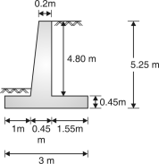
Example 4.5.2 : Design a cantilever retaining wall to retain earth for a height of 4m above ground level. The earth density is 18kN/m3 and its angle of repose is 30. The embankment is horizontal at its top. The SBC of soil is 200 kN/m3 and coefficient of friction between soil and concrete is 0.5. Take M20 grade concrete and Fe415 steel.
Ans:
H2 = 3.5m;=18 kN/m3 ;=30 ;SBC qo=200 kN/m2
= 0.5 ; fck=20N/mm2 ; fy=415 N/mm2
Step 1 : Coefficient of active earth pressure:
Ka = = =
Minimum depth of foundation is
ymin = = = 1.23 m
Provide depth of foundation =1.25 m
Height of retaining wall =4 + 1.25 = 5.25 m
Step 2 : Preliminary dimensions of retaining wall
b =0.5 H to 0.6 H = 0.5 5.25 to 0.6 5.25 = 2.625 m to 3.15 m
Say b =3m
Toe projection =b/3 = 3/3 = 1 m
Thickness of base slab = Thickness of stem = = = 0.4375 m say 0.45 m
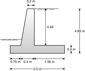
Assume the top width of stem as 0.2 m. Fig. 3.9 shows dimensions of retaining wall. Various forces on retaining wall are shown in Fig. 1-Q. 3.7.
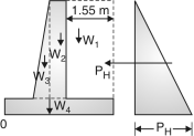
(a) (b)
Fig. 4.9
Step 3: Check for Stability :
| Weight in kN | x(m) | M (kN-m) |
Weight of backfill | W1 = 1.55 4.80 18 = 133.92 | 3 – = 2.225 | 297.972 |
Rectangular portion of stem | W2 = 0.2 4.80 18 = 17.28 | 1 + 0.45 – 0.225 = 1.225 | 21.168 |
Triangular portion | W3 = 0.25 4.80 18 = 10.8 | 1 + 0.45 = 1.3 | 14.04 |
Base slab | W4 = 0.45 3 18 = 24.3 | = 1.5 m | 36.45
|
| W = 186.3 |
| M = 369.63 |
Horizontal pressure pH = Ka H2 = 18 5.252= 81.86kN
Overturning moment M0 = PH= 81.86 = 143.26 kN-m
Factor of safety for overturning F1 = = 2.24 > 1.15.
Hence OK
F2 = = = 0.9 < 1.5
Hence, shear key is to be provided.
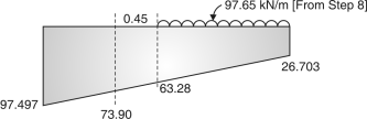
Step 4: Pressure under base slab
Total moment about point O = M – M0 = 369.63 – 143.26 = 226.37 kN-m
Total vertical load =186.3kN
Horizontal distance from O where resultant intersects the base line,
= = 1.215 m
Eccentricity, e = – 1.215 = 0.285 m
Maximum pressure p1 = = = 97.497 kN/m2
Minimum pressure p2 = = 26.703 kN/m2
Thus p1< SBC of soil, hence ok.
Step 5 : Design of stem :
Stem acts as a cantilever of height 4.80 m subjected to a uniformly varying load of Kah
Maximum moment at the base of cantilever
= Kah2 = Kah3 = 18 4.803 = 110.592 kNm
Mu = 1.5 110.592 = 165.888 kN-m
For M20 and Fe415, Mu(lim) = 0.138 bd2 fck
165.888 106 = 0.138 1000 d2 20
d2 = 60.104 103
d = 245.16 mm
Depth d = 350 mm and overall depth D = 400 mm
Main steel :
Mu = 0.87 fy Ast d
165.888 106 = 0.87 415 Ast 350
1312.74 = Ast
Ast2– 16867.5Ast + 1312.74 16867.5 = 0
Ast = 1434.78 mm2
Use 12mm bars
s = 1000 = 86.15mm
Provide 12 mm bars @ 80 mm c/c
Distribution steel :
Average thickness of wall = = 325 mm
Ast = 1000 325 = 390 mm2
Providing 195 mm2 on each face and using 8 mm bars.
S = 1000 = 257.7 mm
Provide 8 mm bars @ 250 mm c/c on tension face.
A mesh of 8 mm bars @ 250 mm is given on compression face of the wall.
Step 6 :Curtailment of vertical bars :
One third of vertical bars are curtailed at a height of 1.6 m from base and another 1/3 at a height of 3.2 m from base.
Check for shear : V = pH = 87.86 kN
Vu = 1.5 81.86 = 122.79 kN
v = = 0.273 N/mm2
P = = 0.20
e = 0.4 N/mm2
No shear R/F is required.
Step 7 :Design of Toe slab
Pressure at face of toe = 26.703 + (97.497 – 26.703)=73.90 kN/m2
M = 73.90 + 1 (97.497 – 26.703) 1=84.17 kN.m
Mu= 1.5 84.17 = 126.25 kN.m
d = 350 mm
126.25 106 = 0.87 415 Ast 350
 999.10 = Ast
A– 16867.5 Ast + 16867.5 999.10=0
Ast = 1066.54 mm2
Using 12 mm bars
s = 1000 = 106.04 mm Fig. 4.10
Providing 12 mm bars @ 300 mm c/c in both directions.
Step 8: Design of Heel slab
Width of heel slab = 1.55 m
Pressure at the face of column = 26.703 + (97.497 – 26.703)=63.28 kN/m2
Weight of back fill = γH1 = 18 4.80 = 86.4 kN/m
Self weight = 0.45 1 25 = 11.25 kN/m
Total load = 86.4 + 11.25= 97.65 kN/m
Mmax = 97.65 – 26.703 – (63.28 – 26.703) 1.55 1.55
= 70.725 kN-m
Mu = 1.5 70.725 = 106.08 kN-m
Main steel :
106.08 106 = 0.87 415 Ast 350
839.52 = Ast
A– 16867.5 Ast + 839.52 16867.5 = 0
Ast = 886.05 mm2
Use 12mm bars,
s = = 127.6 mm
provide 12 mm bars @ 120 mm c/c in both directions.
Step 9 :Design of shear key
Pressure at face of shear key = 73.90 kN/m2
Coefficient of passive earth pressure
Kp = = 3
If ‘a’ is the projection of shear key, resistance offered by passive earth pressure.
= Kp vertical pressure = 3 73.9 a = 221.7a kN
Factor of safety against sliding F2 = = 1.5
= 1.4 83.835 + 221.7a = 114.604 a = 0.138 m
Provide 200 mm deep shear key.
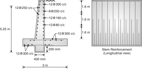
Fig. 4.11
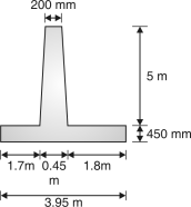
Example 4.5.3: Design the stem of a RC cantilever retaining wall, retaining leveled earth 5 m above the base level. Take the density of earth as 18 kN/m3 and angle of repose as 30. Toe projection 1.8 m, heel projection 1.7m, thickness of base slab as 450 mm.
 Ans.:
Ans.:
= 18 kN/m3
Ka = = =
Stem acts as a cantilever of height 5 m subjected
To a uniformly varying load of Kah.
Maximum moment at the base of cantilever
= Kah2 = Kah3 = 18 53
= 125 kN-m
Assume M20 concrete grade and Fe245 steel. Fig. 4.12
Mu = 0.87 fy Ast d
125 106 = 0.87 415 Ast 450
769.36 = Ast
A– 21686.7 Ast + 769.36 21686.7 =0
Ast = 798.78 mm2
Using 12 mm bars s = = 141.58 mm
Provide 12 mm @ 140 mmc/c
Distribution steel :
Average thickness of well = = 325 mm
Ast = 1000 325 = 390 mm2
Providing 195 mm2 on each face and using 8mm bars.
s = = 257.77 mm
Provide 8 mm bars @ 250 mm c/c on tension face.
A mesh of 8 mm bars @ 250 mm is given on compression face of the wall.
Curtailment of vertical bars :
One third of vertical bars may be curtailed at a height of 1.67 m from base and another one third at a height of 3.33 m from base as shown in Fig.3.13.
Check for shear:
V = PH = KaH2 = 18 52 = 75 kN
Vu = 1.5 75 = 112.5 kN, V = = 0.25 N/mm2
P = = 0.25
c =0.4N/mm2 No shear R/F is required.
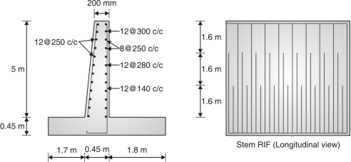
Fig. 4.13
Example 4.5.4: Determine the dimensions of a T-shaped retaining wall for a height of 5 m above the ground level. The top of the earth is surcharged at 20 with horizontal. The angle of repose of earth is 30 and its density is 20kN/m3. The safe bearing capacity of soil is 50 kN/m2 and coefficient of friction between concrete and soil is 0.55.
Ans.:
H2 = 5m; =20 kN/m3; =30 ; SBC q0=90 kN/m2
= 0.55; fck=20 N/mm2 ; fy=415 N/mm2
Ka = = =
Minimum depth of foundation
= = = 1.5 m
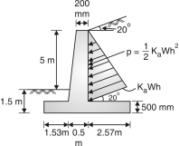
Provide a minimum depth of 1.5 m below ground level.
Total height of retaining wall = 5 + 1.5 = 6.5 m
Use 500 mm thick base slab
Height of stem = 6.5 – 0.5 = 6 m
Let the top width of stem = 200 mm
Width of base slab= 0.7H = 0.7 6.5 = 4.55 m 4.6 m
Width of toe = 4.6/3 = 1.53 m
Fig. 4.14
Example 4.5.5: Design the vertical stem of a T-shaped retaining wall for a height of 3.5 m above the ground level. The top of earth retained is horizontal. The angle of repose of earth is 30 and its density is 20 kN/m3. The safe bearing capacity is 100 kN/m2. Use M25 grade concrete and Fe415 grade steel.
Ans.:
H2 = 3.5 m ; =20 kN/m3 ; =30; q0=100 kN/m2 ;
= 0.5 (assume); fck=25 N/mm2; fy=415 N/mm2
Coefficient of active earth pressure Ka = = =
Minimum depth of foundation = = = 0.55 m
Provide depth of foundation = 1m
Height of retaining wall = 3.5 + 1 = 4m
Preliminary dimensions of Retaining wall :
b = 0.5H to 0.6H = 0.5 4 to 0.6 4 = 2 m to 2.4 m
Provide b = 2.4m Toe projection = = = 0.8 m
Thickness of base slab=thickness of stem = = = 0.33 m
Say 0.4 m
Let top of width of stem = 0.2 m
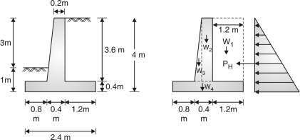
Fig. 4.15
Stability check:
| Weight in kN | x(m) | Ms (kN-m) |
Weight of backfill | W1 = 1.2 3.6 20 = 86.4 | 2.4 – = 1.8 | 155.52
|
Rectangular portion of stem | W2 = 0.2 3.6 25 = 18 | 0.8 + 0.4 – 0.1 = 1.1 | 19.8
|
Triangular portion | W3 = 0.2 3.6 25 = 9 | 0.8 + 0.2 = 0.93 | 8.4
|
Base slab | W4 = 0.4 2.4 25 = 24 | = 1.2 | 28.8
|
| W = 137.4 |
| 212.52 |
Horizontal pressure PH = KaH2 = 20 42 = 53.33kN
Overturning moment M0 = PH= 53.33 = 71.1 kN.m
F1 = = 2.68 > 1.4 …OK
F2 = = = 1.159 < 1.4
Hence shear key is to be provided.
Design of stem:
Maximum moment at the base of cantilever
= Kah2 = Kah3 = 20 43 = 71.11kN.m
Mu = 1.5 71.11 = 106.67 kN-m=0.87 fy Ast d
106.67 106 = 0.87 415 Ast 350
844.125 = Ast
A– 21084.33Ast + 844.125 21084.33 = 0
Ast = 880.93 mm2
Using 12 mm bars, s = = 128.38 mm
Provide 12mm @ 120 mm c/c.
Distribution steel:
Average thickness of wall = = 300 mm
Ast = 1000 300 = 360 mm2
Providing 180 mm2 on each face and using 8 mm bars.
s = = 279 mm
Provide 8mm @ 270 mm c/c on tension side.
A mesh of 8mm @ 270 mm c/c is given on compression side of the wall.
Curtailment of vertical bars:
One third of vertical bars may be curtailed at a, height of 1.2 m from base and another one third at a height of 2.4 m from the base.
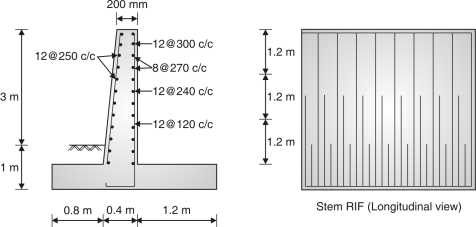
Fig. 4.16
Example 4.5.6: A cantilever retaining wall retains an earth embankment with a horizontal top 3.75m above ground level. Design the stem for following data: Density of earth = 19 kN/m3, Angle of internal friction = 30, SBC of soil = 180 kN/m2 Coefficient of internal friction between soil and concrete = 0.5, M20 concrete grade and Fe 415 grade steel.
Ans.:
Given data:
H2 = 3.75m, r = 19 kN/m3, = 30, SBC q0 = 180 kN/ m2 , = 0.5, fck = 20 N/mm2,
fy = 415 N/mm2 .
Coefficient of active earth pressure = ka = = =
Minimum foundation depth ymin = = = 1.05m
 Provide foundation depth = 1.1m
Height of retaining wall = 3.75 + 1.1 = 4.85 m
Preliminary dimensions:
B = 0.5 H to 0.6 H = 0.5 4.85 to 0.6 4.85
= 2.425 m to 2.91m
Assume b = 2.5 m
Toe projection = b/3 = 2.5/3 = 0.83
Provide 0.75 m
Thickness of base slab = Thickness of stem
= = = 0.4m
Assume top width of stem = 0.2m.
Fig.4.17: Preliminary dimensions
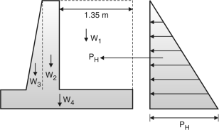
Fig. 4.18: Forces on retaining wall
Stability check:
| Weight(kN) | x(m) | M(kN-m) |
Weight of backfill | w1 = 1.35 4.35 19 = 111.58 | 2.5 – = 1.825 | 203.63 |
Rectangular portion of stem | w2 = 0.2 4.45 19 = 16.91 | 0.75 + 0.4 – 0.1 = 1.05 | 17.76 |
Triangular portion of stem | w3 = 0.2 4.45 25 = 11.125 | 0.75 + 0.2 = 0.88 | 9.79 |
Base slab | w4 = 0.4 2.5 25 = 25 | 2.5/2 | 31.25 |
| W = 164.615 |
| M = 262.43 |
Horizontal pressure PH = karH2 = 19 4.852 = 74.49 kN
Overturning moment Mo = PH = 74.49 = 120.42 kNm
Factor of safety for overturning F1 = = 1.96 > 1.4
Hence O.K.
F2 = = = 0.99 < 1.4
Design of stem:
Maximum moment at the base of cantilever
= karh2 = 19 = 93.02 kNm
Mu = 1.5 93.02 = 139.525 kNm
Mu(lim) = 0.138 bd2fck
139.525 106 = 0.138 1000 d2 20
d = 224.84 mm
Provided = 350mm and D = 400 mm
Ast = 0.5
= 0.5 20
= 1188.40mm2
 Use 12 mm bars.
S = 1000 = 95.16 mm
 Provide 12 mm @ 90mm c/c
Distribution steel:
Average thickness of wall = = 300 mm
st = 1000 300 = 360 mm2
Provide 180 mm3 on each face.
Use 8mm bars
S = 1000 = 279 mm
Provide 8mm bars @ 270 mm c/c on tension face and compression face.
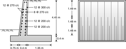
Fig.4.19: Reinforcement details
Example 4.5.7: Design of heel slab and stability analysis of a cantilever retaining wall is to be carried out for the following data: Height of horizontal backfill = 3.5m, Concrete grade = M20, Steel = Fe415, Backfill density = 18kN/m3, Angle of friction = 30 coefficient of friction between soil and concrete = 0.5, SBC of soil = 150 kN/m3 , depth of foundation = 1.1 m.
Ans.:
H2 = 3.5m, r = 18kN/m3, = 30, SBC q0 = 150 kN/m2, M = 0.5, fck = 20N/mm2
fy= 415 N/ mm2
Coefficient of active earth pressure = ka = = =
 Depth of foundation = 1.1 m
Height of retaining wall = 3.5 + 1.1 = 4.6m
Preliminary Dimensions of Retaining Wall :
B = 0.5 H to 0.6H = 0.5 4.6 to 0.6 4.6
= 2.3 m to 2.76m
Say b = 2.5m
Toe projection = b/3 = 0.75m
Thickness of base slab = Thickness of stem
= =
= 0.38 m say 0.4m.
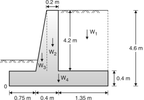
Let top width of stem = 0.4 m
Fig. 4.20: Forces on retaining wall
Stability check:
| Weight (kN) | x(m) | M(kNm) |
Weight of backfill | w1 = 1.35 4.2 18 = 102.06 | 2.5 – = 1.825 | 186.26 |
Rectangular portion of stem | w2 = 0.2 4.2 25 = 21 | 0.75 + 0.4 – 0.1 = 1.05 | 22.05 |
Triangular portion of stem | w3 = 0.2 4.2 25 =10.5 | 0.75 + 0.2 = 0.88 | 9.24 |
Base slab | w4 = 0.4 2.5 25 = 25 | 2.5/2 | 31.25 |
| W = 158.56 |
| W = 248.8 |
Horizontal pressure PH = karH2 = 18 4.62 = 63.48 kN
Overturning moment M0 = PH = 63.48 = 97.336 kNm
Factor of safety for overturning F1 = = 2.30 > 1.4 Hence O.K.
F2 = = = 1.12 < 1.4
Design of heel slab :
Total moment about ‘o’ = M – M0 = 248.8 – 97.336 = 151.46 KN.m
Total vertical load = 158.56 kW
Horizontal distance from o where resultant intersects base line.
= = 0.955 m
 Eccentricity e = – 0.955 = 0.295 m
Maximum pressure
P1 = =
= 108.32 kN/m2
Maximum pressure P2 =
= 18.52 kN/m2
Fig. 4.21
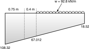
Fig. 4.22: Base pressure
0 – 18.52 1.35 – x
2.5 – 108.32 2.5 – 89.8
Pressure intensity at1.35m 1.35 – x x = = 48.492
= 18.52 + 48.492=67.012 kN/m2
Weight of backfill = rH1 = 18 4.6 = 82.8 kN/m
Self weight = 0.4 1 25 = 10 kN/m
Total downward load w = 82.8 + 10= 92.8 kN/m
Mmax = 92.8 – 18.52 – (67.012 – 18.52) 1.35 1.35
= 52.96 kN-m
Mu = 1.5 52.96 = 79.43 kNm
Ast = bd
= 1000 350=654.25 mm2
Provide minimum reinforcement of 12 mm bars @ 225 mm c/c in both directions.
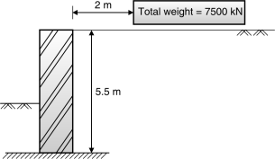
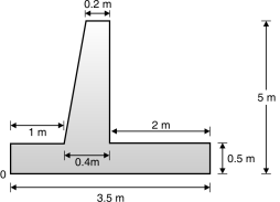
Example 4.5.8: Design cantilever retaining wall for following data: Height of wall = 5.5m, Depth of foundation 1.2 m, Density of soil = 19 kN/m3, Angle of internal friction = 34,
SBC of soil = 225 kN/m2 coefficient of friction base and soil = 0.5. At the top level of backfill, a rectangular GSR is constructed 2m away from wall whose plan details are as below:
(i)Plan area = 15m 50 m (ii) Material M25 and Fe 415, (iii) Total weight of GSR under
full water condition = 7500 kN.
 Ans. :
Fig. 4.23: Retaining wall
= 34, H = 5.5m, r = 19kN/m3, SBC q0 = 225 kN/ m2 ,=0.5, fck = 20 N/mm2, fy = 415 N/mm2
Coefficient of active earth pressure Ka = = =
Preliminary dimensions of Retaining wall:
B = 0.5H to 0.6 H = 0.5 5.5 to 0.6 5.5 = 2.75m to 3.3m
Provide b = 3m
Toe projection = b/3 = 3/3 = 1m
Thickness of base slab = Thickness of stem = = = 0.46 m 0.5m
Let top width of stem is 0.2 m
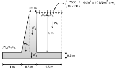
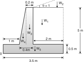
Fig. 4.24: Forces on retaining wall
Stability check:
| Weight (kN) | X(m) | M(kNm) |
Weight of backfill | w1 = 1.5 5 19 = 142.5 | 3 – = 2.25 | 320.625 |
Rectangular portion of stem | w2 = 0.2 5 25 = 25 | 1.1 + 0.5 – 0.1 = 1.5m | 37.5 |
Triangular portion of stem | w3 = 0.3 5 25 = 18.75 | 1.1 + 0.3 = 1.3 | 24.375 |
Base slab | w4 = 0.5 3 25 = 37.5 | 3/2 | 56.25 |
Water tank | w5 = 10 1.5 5 = 75 | 3 – = 2.25 | 168.75 |
| W = 298.75 |
| M = 607.5 |
Horizontal pressure PH = KarH2 = 19 5.52 = 81.18 kN
Overturning moment M0 = PH = 81.18 = 148.83 kN-m
Factor of safety for overturning
F1 = = 3.67 > 1.4 Hence O.K.
F2 =  = = 1.65 > 1.4
Hence, shear key need not be provided.
Pressure under Base slab:
Total moment about O = 607.5 – 148.83 = 458.67 kNm
Total vertical load = 298.75 kN
= = 1.53 m
Eccentricity e = – 1.53 = – 0.03 mm
e < b/
0.03 < 0.5
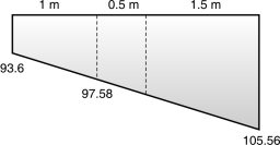
Maximum pressure = = =105.56 kN/m2
Minimum pressure = = 93.6 kN/m2
Design of stem:
Maximum moment at base of cantilever
= ka rh2 = 19 = 148.8 kNm
Mu = 1.5 148.8 = 223.24 kNm
Mu(lim)= 0.138 bd2fck
223.24 106 = 0.138 1000 d2 20
d = 284.40 mm
Provide d = 450mm and overall depth D = 500 mm
Ast =
= =1475 mm2
 Use 12m m bars, S = 1000 = 76.67 mm
 Provide 12 mm bars @ 75mm c/c
Distribution steel:
Average thickness of wall = = 350 mm
Ast = 1000 350 = 420 mm2 (Provide half on each face)
Use 8mm bars
S = = 239.3mm
Provide 8mm bars @ 230 mm c/c on tension face and compression face of the wall.
Curtailment of vertical bars:
One third of vertical bars are curtailed at a height of 1.67m from base and another one third at 3.33m from base.
Check for shear:
V = PH = 81.18 kN Vu = 1.5 81.18 = 121.77kN
v = = 0.27 N/mm2
Pt = = = 0.25 %
c = 0.4 N/mm2 v < v <cmax
No shear reinforcement is required.
 Design of Toe slab :
0 – 105.56 2 – ?
3 – 93.6 3 – 11.96
2 –?
Pressure at face of toe = 97.58 x = 7.97
M = 97.58 + 1 (97.58 – 93.6 ) 1
= 48.79 + 1.32=50.11 kNm Fig. 4.25 : Base pressure
Mu = 1.5 50.11 = 75.175 kN.m
d = 450 mm
Ast =
= =473.25mm2
Astmin = 1000 450= 540 mm2
Use 12mm bars S = (/4) 122 1000/540 = 209.44 mm
 Provide 12mm @ 300mm c/c in both directions
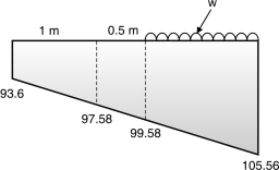
Design of steel slab:
0 – 105.56
1.5 – A
3 – 93.6
 3 – 11.96
1.5 – x
x = = 5.98
A = 105.56 – 5.98 = 99.58 kN/m2
Fig. 4.26: Base pressure
Weight of backfill = rH1 = 19 5 = 95 kN/m
Self weight = 0.5 3 25 = 37.5 kN/m
Weight of water tank = 10 1.5 5 = 75 kN/m
Total downward load = 207.5 kN/m
Max. Bm = – 105.56 – (105.56 – 99.58)1.5
= 233.44 – 118.755 – 2.242=112.44 kNm
Mu = 1.5 112.44 = 168.66 kN-m
Ast = =1093.79 mm2
 Use 12mm bars.
S = = 103.39 mm
 Provide 12 mm @ 100 mm c/c in both directions.
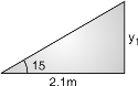
Example 4.5.9: Design an RCC cantilever retaining wall to retain earth embankment 4 m height above the G.L. The angle of surcharge is at an angle of 15 to horizontal weight of soil and its angle of repose is 18 kN/10m3 and 30 respective. The good foundation is available at depth of
1 m below GL, the SBC of soil = 160 kN/m3 coefficient of friction - – 0.62. Use M20 and Fe415.
Ans.:
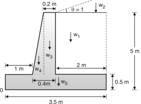
Given: Df = 1 m ; H = 4 + 1 = 5 m
1. Preliminary s/c.:
(a) Assuming top width = 120 mm
(b) Width of base slab = 0.55 H to 0.75 H
=0.55 5 to 0.75 5
= 2.75 to 3.75 M
Assuming B = 3.5 m
(c)Toe projection= or = or = 0.83 or 1.167
Assuming Toe projection = 1 m
(d) Thickness of base = to = 0.33 to 0.5 m
Fig. 4.27
Assuming thickness of base = 0.5 m
Thickness of vertical wall
Fa = H2 kah2
Ka = cos ,
= 15 , = 30
Ka = 0.373
Pa = 0.373 18 (4.5)2 = 67.97 kN
PaH = Pa cos = 67.97 cos 15 = 65.65 kN
Moment = PaH = 65.65 (at base max) = 98.48 kN-m
98.48 106 = 0.138 fck bd2,
Factored Mu= 98.48 1.5 = 147.71 106 N-mm
Mu = Mulim ,147.71 106 =0.138 fck bd2
 147.71 106=0.138 20 1000 d2, d=231.34 mm
D = d + cover = 231.34 + 40 = 271.34
AssumingD=400 mm
d = 400 – 40 = 360 mm
Since the thickness or toe and heel slab
The height of vertical wall. So the design
Of v wall should be taken after toe and heel
1. Width of heel slab :
= 3.5 – 1 – 0.4 = 2.1 m
2. Force on the body:
Fig. 4.28: Geometry of retaining wall
(i) Earth pressure:
 Pa = Ka w = 0.373 18 (5 + 0.56)2
= 103.78 kN
PaH = Pa cos = 103.78 cos 15
= 100.24 kN
(ii) Self weight:
(a) Weight of earth upto top
w1 = Area × Density of soil;
w1 = 2.1 × 4.5 × 18 = 170.1
x1 = + 0.4 + 1 = 2.45 m
(b) Weight of soil above top
 w2 = × 2.1 × 0.56 × 18 = 10.58 kN
x2 = × 2.1 + 0.4 + 1 = 2.8 m
(c) Weight of vertical wall
w3 = 0.2 × 4.5 × 25 = 22.5 kN; x3
= 1 + (0.4 – 0.2) + = 1.3 m
Weight of triangular portion of vertical wall
w4 = × 0.2 × 4.5 × 25 = 11.25 kN
x4 = × 0.2 + 1 = 1.13 m Fig. 4.29
(d) Weight of base slab
w5 = 3.5 × 0.5 × 25 = 43.75 m; x5 = 1.75 m
w = w1 + w2 + w3 + w4 + w5 = 258.18 kN
wx = (w1x1 + w1x2 + w3x3 + w4x4 + w5x5) = 564.89 kN.m
3. Check against stability:
(a) Check for overturning, overturning moment
= 1.2 × 1 + = 1.2 × 100.24 × =222.93 kN-m
Restoring moment = 0.9 × wx = 0.9 × 564.89 = 508.4 kN-m
Restoring moment > overturning moment
508.4 > 222.93 safe.
(b) Check for sliding :
Sliding force = 1.4 × PaH = 1.4 × 100.24 = 140.34 kN
Restoring force = 0.9 w = 0.9 × 0.62 × 258.18 = 144.06 kN
Restoring force > sliding force Safe.
(c) Check for base pressure:
1. Considering Pav :
MToe = wx – PaH × + Pav × B
v = w + PaH = 258.18 + 26.86 = 285.04 kN
MToe = 564.89 – 100.24 + 26.86 3.5 = 473.12 kN.m
Z = = = 1.66 e = – Z = – 1.66 = 0.09
Pmax = = = 94.00 ≯ SBC ok.
(b) Neglecting Pav :
MToe = wx – =564.89 – 100.24 = 379.11 kN-m
v = w = 258.18 kN Z = = = 1.47
e = – z = 0.28 Pmax = =
= 109.17 kN≯ SBC safe
Pmin = = = 38.36 > 0 safe
4. Design of toe slab:
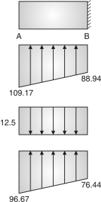
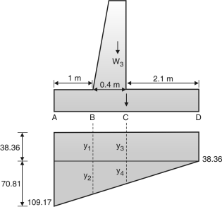
Fig. 4.31: Base pressure Fig. 4.32: Resultant pressure
From similar
= y2 = 50.58
Total = y1 + y2 = 38.36 + 50.58=88.94
= y4 = 42.486
Total = y3 + y4 = 38.36 + 42.486 =80.85
Resultant pressure
At A = 109.17 – 12.5 = 96.67 kN/m3
At B = 88.94 – 12.5 = 76.44 kN/m3
Self weight = 0.5 25 = 12.5
Shear force = Area of + Area of rectangle = (1) (96.67 – 76.44) + (1) 76.44
= 86.55 kN
Factored SF = 1.5 86.55 = 129.825 kN
BM = (Area of C.G. Distance) + (Area of C.G. Distance)
= + 76.44 1 0.5 = 44.96 kN-m
Mu = 1.5 45.96 = 68.94 kN-m
Check for depth:
Mu = Mulim 67.44 106 = 0.138 fck bd2
67.44 106 = 0.138 20 1000 d2
d = 156.32
D = 156.32 + 40=196.32 mm <Dassumed
Provide D = 500 m
d = 460 mm
Area of steel:
Ast = bd
= 1000 460 = 423.39 mm2
Astmin = b D = 600 mm2 as Ast<Astmin
Providing Ast = 600 mm2 Ld + lo
47 + 46020.84

 Assuming 12 mm bars
Spacing = = 188.49 < 3 d or 300 ok.
Providing 12 mm bar @ 180 mm c/c
Area of distribution steel:
= b D = 1000 460 = 552 mm2
Provide Astmin= 600mm2
Assuming 8 mm bars
Spacing = = 83.77 ≅ 80 mm ok.
Check for shear:
v = = = 0.28 N/mm2
Point % = = = 0.136 %
c = 0.28 N/mm2; v = c
Design of shear reinforcement is not required
(6) Design of heel slab :
Resultant pressure
(a) At c = 80.85 – 12.5 – 72
= – 3.65
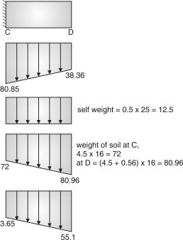 (b) At D = 38.36 – 12.5 – 80.96
= – 55.1
Max S.F = Area of + Area of
= 2.1 (55.1 – 3.65) + 3.65 2.1
= 61.69 kN
Factored SF = 1.5 61.69 = 92.53 kN
BM= (Area of cg. Dist) + (Area of cg. Dist)
= + 3.65 2.1
= 83.68 kN-m
Factored B.M. = 1.5 83.68 = 125.52
Check for depth:
Mu = Mulim
125.52 106 = 0.138 1000 d2 20
d = 213.25
D = 213.25 + 40 Fig. 4.33: Pressure diagrams
= 253.25 mu < depress o.k.
Provide D = 500 mm d = 460 mm
Area of steel:
Ast = 1000 460=783.86 mm2
Ld = + ld 47 = + 460
= 38.65 mm
 Assuming 16 mm bars
Spacing = = 256.5 < 3d or 300 mm
 Provide 16 mm @ 250 mm.
Distribution steel:
Ast = b D = 1000 500 = 600 mm2
 Assuming 8 mm bars
Spacing = = 83.77
 Providing 8 mm
Check for shear:
pt | c |
0.15 | 0.28 |
0.25 | 0.36 |
v = = = 0.2 N/mm2
pt = = = 0.17
c = 0.28 + (0.17 – 0.15) = 0.296 N/mm2
k = 1
v < c 0.2 < 0.296
Shear reinforcement is not required.
(7) Design of vertical wall
Pa = Kaw = 0.373 16 (4.5 + 0.56)2=76.40 kN
PaH = Pa cos = 76.4 cos 15 = 73.79
pav = Pa sin = 19.77
BM at base = PaH = 73.79 = 124.46 kNm
Mu = 1.5 124.46 = 186.69
Check for depth:
Mu = Mulim 186.69 106 = 0.138 1000 d2 20
d = 260.07 D = 300.07 < Dassumed (400) ok.
providing D = 400 mm d = 360 mm
Area of steel = bd
= 1000 360 = 1581.13
ld + lo
Shear force, v = PaH = 73.79 vu = 1.5 73.79 = 110 .68
ld + 360
47 2046.75 43.54
 Providing 20 mm bars
Spacing = =198.69 mm < 3d or 300 mm
 Providing 20 mm 190 mm c/c
Curtailment: pressure at half height
Pressure at = 2.25 from Top
Pa = 0.373 16 (2.25 + 0.56)2 = 23.56 kN
PaH = Pa cos = 23.56 cos 15 = 22.75 kN
BM = PaH = 22.75 = 21.31 kN-m
Mu = 1.5 21.3 = 31.965 kN-m D = = 0.3 m
d = 300 – 40 = 260 mm
Ast = = 260 1000
= 350.48 mm2
(Ast)min = 1000 300 = 360 mm
Providing Ast 360 mm2
Assuming 12 mm  bar
bar
Spacing = = 314 < 3d or 300 ≅ 300 mm
Check for shear :
SF = PaH = 73.79 kN
Factored SF = vu = 1.5 73.79 = 110.685 kN
v = = = 0.307
pt = = = 0.465
pt c
0.25 0.36
0.5 0.48
c = 0.36 + (0.465 – 0.25) = 0.46
k = 1 c = 0.46
v < c safe.
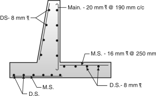
Fig.4.34: Reinforcement details
Example 4.5.10: For the cantilever wall of height 3.5m, fix the basic dimensions of various elements. The angle of repose of soil is 30. SBC of soil is 200 kN/m3 and density of soil is 18 kN/m3. Friction coefficient between soil and concrete is 0.55. Do the check for stability, sliding and overturning. Design the stem of the retaining wall.
Ans.:
H2 = 3.5m, γ = 18kN/m3, = 30, SBC q0 = 200 kN/m2, μ = 0.5, fck = 20N/mm2
fy= 415 N/ mm2
Coefficient of active earth pressure = ka = = =
Minimum depth of foundation is
ymin = = = 1.23 m
Provide depth of foundation = 1.25 m
Height of retaining wall =3.5 + 1.25 = 4.75 m
Preliminary Dimensions of Retaining Wall:
B = 0.5 H to 0.6H = 0.5 4.75 to 0.6 4.75
= 2.375 m to 2.85m
Say b = 2.7m
Toe projection = 2.7/3 = 0.9m
Thickness of base slab = Thickness of stem
= 
= 0.395 m say 0.4m.
Let top width of stem = 0.2 m
4.6.1 Various parts of a counter fort retaining wall:
A counter fort retaining wall is to be provided where the height of earth fill is greater than 6m.
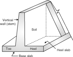 Fig. **
Fig. 4.35: Parts of counter fort retaining wall
4.6.2 Design steps for a counter fort retaining wall:
Design steps:
1. Tentative trial section.
2. Forces
3. Stability check
(i) Overturning (ii) Sliding (iii) Base pressure
4. Design of section
(i) Vertical wall
 (ii) Toe slab
(iii) Heel slab
(iv) Counter fort
(I) Trial section:
1. Base width = 0.6 H to 0.7 H (H = total height of wall)
2. Toe width = to or
3. Thickness of vertical walls @ 0.3 m
 4. Counter fort thickness @ 0.4 m
5. Thickness of base slab = 2l or 4l
l – Spacing of counter fort in m
H – Height in m
4.6.3 Various forces acting on a counter fort retaining wall:
Forces:
(1) Horizontal back fill :
Intensity of earth pressure = Ka wH
Ka = Coefficient of active earth pressure.
Ka =
w = unit weight of soil
= angle of repose Fig. 4.37 : Pressure distribution diagram (Horizontal backfill)
Total pressure = Ka wH H Pa = KawH2
(2) Inclined backfill (with surcharge) :
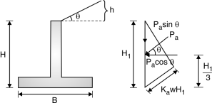
Fig. 4.38: Pressure distribution diagram (Inclined backfill)
Active earth pressure, Pa = Ka w
Ka = cos
Where, = angle of surcharge = angle of repose
(3) Passive earth pressure:
The passive earth pressure is exerted when it has tendency to move towards the backfill such a case may occur when the retaining wall supports soil of different depths on both.
PP = Kp wH2 Kp =
(4) Self weight of wall
(i) Weight of earth (without surcharge)
 w1 = width height density of soil
x1 = distance of load w1 from toe i.e. (A)
(ii) Weight of earth (with surcharge)
w2 = Area of triangle density of soil
x2 = distance of load w2 from A
(iii) Weight of wall
w3 = Thickness height density of conc.
x3 = distance of load w3 from A
Fig. 4.39: Loads of different part
In retaining wall
(iv) weight of base slab
w4 = Thickness width Density of conc
x4 = distance of load w4 from A
w = w1 + w2 + w3 + w4 M @ A
MToe = w1 x1 + w2 x2 + w3 x3 + w4 x4
4.6.4 Stability check for a counter fort retaining wall:
(i) Check against overturning : (Pg 33, cl-20.1)
(1) Overturning moment = Pa
(2) Restoring moment = wx = w1 x1 +w2 x2 + w3 x3 ….
0.9 Restoring moment 1.2 overturning moment
0.9 wx 1.2 Pa ( safe)
If unsafe change the dimensions
(ii) Check against sliding : (clause 20.2)
(1) Sliding force = 1.4 Pa
(2) Restoring force = 0.9 w
Restoring force sliding force
0.9 w 1.4 Pa …Ok
If it is unsafe there is no need to change the dimensions but provide shear key.
(iii) Check for base pressure :
(1) Maximum pressure = Pmax =
Eccentricity = e = – z z =
Pmax S.B.C. Of soil
(2) Maximum pressure = Pmin = 0
Problems based on Design of Counterfort Retaining Walls
Example 4.6.5: Design a retaining wall for the following data.
(1) Height above GL = 6M. (2) Depth of foundation below GL = 1m
(3) The density of soil = 16 kN/m3 (4) Angle of repose = 30
(5) Surcharge = 10 (6) SBC of foundation = 150 kpa
(7) Coefficient of friction = 0.6.
Use M20 and Fe 415. The counter fort is on earth side only.
Ans.:
(1) Preliminary section:
Total height of wall = H = 6 + 1 = 7m
(i) Base width = 0.6H to 0.7H=0.6 7 to 0.7 7=4.2 to 4.9 m
Assuming B = 4.5 m
(ii) Toe width = to or = to or = 1.5 to 1.125 or 1.17
Assuming toe width = 1.2 m
(iii) Assuming thickness of vertical wall = 0.5 m
(iv) width of heel slab = 4.5 – 1.2 – 0.25 = 3.05 m
(v) Thickness of base slab = 2lH or 45
Assuming l = spacing of counter fort = 3.5 m
Thickness of base slab = 37 or 49
Assuming = 40 cm
(2) Forces on retaining wall:
(i) Earth Pressure H1 = H + y1
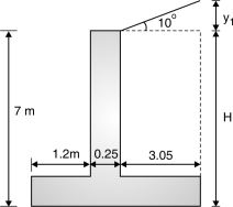
Fig. 4.40: Geometry of retaining wall

H1 = 7 + 0.54=7.54 m
Pa = Ka w Fig. 4.41: Height of surcharge
 w = Specific weight of soil
= 16 kN/m3 (given)
Ka = cos
Tan 10 =
y1 = 0.54 m
– angle of surcharge
= 10 and – angle of repose
= 30
Ka = 0.35 Fig. 4.42: Loads and pressure
Distribution diagram
Pa = 0.35 16 (7.54)2=159.18 kN
Acting at H1/3 from base = = 2.51m from base
Horizontal component PaH = Pa cos =159.18 cos 10=156.76 kN
Vertical comp Pav = Pa Sin = 27.64 kN
(3) Self weight:
(i) Weight of soil (up to top)
w1 = area density of soil = 3.05 (7 – 0.4) 16 = 322
x1 = 3.05/2 + 0.25 + 1.2=2.975 m
(ii) Weight of surcharge,
w2 = ½ 3.05 0.54 16 = 13.2 kN
x2 = 2/3 3.05 + 0.25 + 1.20 = 3.48 m
(iii) Weight of vertical wall (stem)
w3 = 0.25 6.6 25 = 41.25 kN x3 = 1.2 + = 1.325 m
(iv) Weight of base slab,
w4 = 0.4 4.5 25 = 45 kN x4 = = 2.25
w = w1 + w2 + w3 + w4 = 421.55 wx = w1 x1 + w2 x2 + w2 x3 + w4 x4
wx = 1158.48 kN – m
(4) Check for stability:
(i) Check against overturning:
Overturning moment = 1.2 PaH=1.2 156.76 = 472.78 kN – m
Restoring moment = 0.9 Wx=0.9 (1158.48)=1042.63
Restoring moment > overturning moment
safe against overturning
(ii) Check against sliding:
Sliding force = 1.4 PaH = 1.4 156.76=219.46 kN
Restoring force = 0.9 w=0.9 0.6 421.55=227.64 kN
(iii) Restoring force is greater than sliding force safe
Check against base pressure:
(a) Considering Pav :
Moment @ Toe = MToe = w1 x1 + w2 x2 + w3 x3 + w4 x4 + Pav B – PaH
= 1158.48 + 27.64 4.5 – 156.76
MToe = 888.86 –m Z = =
v = 421.55 + 27.64 = 449.19 kN Z ==1.978 1.98
e = – z = – 1.98 = 0.27
Pmax = =
≯S.B.C.(150 kN/m2)=135.74 ≯150
Pmin = => 0
= 63.88 > 0 OK.
(b) Neglecting Pav :
MToe = w1 x1 + w2 x2 + w3 x3 + w4 x4 – PaH=1158.48 – 156.76
= 766 kN – m
v = w = 421.45 kN Z = = = 1.81
e = – Z = – 1.81 = 0.44
Pmax = ≯ S.B.C.=
≯150 kN/m2 =148.6 ≯150
OK
Pmin = > 0=> 0=38.72 > 0 OK
(5) Design of vertical wall:
(i) A vertical wall is designed as vertical continuous slab spanning between counter forts
Span = spacing of counter fort = 3.5 m
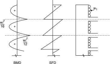
Fig. 4.43: Shear force and Bending moment distribution diagram
Horizontal component of base pressure w1 = ka w H1 cos
Ka – coefficient of active earth pressure
w – Density of soil
w1 = 0.35 16 (7.54 – 0.4) cos 10=39.37
Maximum BM = = = 40.19 kN.m
l = spacing of counter fort
Ultimate BM = Mu = 1.5 40.19=60.29 kN.m
Maximum S.F = 0.6 w1l
V = 0.6 × 39.37 × 3.5=82.67 kN
Vu = 1.5 × V = 1.5 × 82.67 = 124.01 kN
(ii) Check for depth:
Maximum BM = Mu lim Mu = Mulim
60.29 × 106 = 0.138 bd2 fck 60.29 × 106 = 0.138 × 1000 × d2 × 20
d = 147 mm
Assuming cover 40 mm.
Dread = d + cover = 147 + 40
= 187 mm < Dassumed
< 250 mm
Providing D = 250 mm and d = 210 mm
(iii) Area of steel:
(a) Area of main steel,
Ast =
Bd = 100 × 2
= 870.42 mm2 ld + lo
ld = = = 47 …. For M20 and Fe415.
47 + 210 14.81
Providing 12 mm dia bar.
Spacing = = 129.93 < 3d or 300 ok.
Providing 12 mm diameter bar @ 120 mm c/c from base upto 3.3. m.
Curtailment:
Providing 12 mm diameter bar @ 240 mm c/c at 3.3 m from base and upto top of wall.
(b) Area of distribution steel = × b × D= × 1000 × 250 = 300 mm2
Assuming 8 mm diameter bar.
Spacing = = 167.59 < 5 d or 450 mm
Providing 8 mm @ 160 mm c/c.
(iv) Check for shear IS : 456-2000/Page 73/table 19
Pt % | c |
0.25 | 0.36 |
0.5 | 0.48 |
v = = = 0.59 N/mm2
pt % = =
pt % = 0.44
c = 0.36 + (0.44 – 0.25) = 0.45 N/mm2
v > c
Design of shear reinforcement is required
Design shear force = Vus
Vus = u – c bd = 124 × 103 – 0.45 × 1000 × 210 = 29.51 × 10³ N
sv =
Assume 8 mm 5 legged stirrups.
(1) sv = = 645.7 mm
(2) sv = = =226 mm
(3) sv = 0.75 d or 300 mm = 0.75 × 210 or 300 = 157.5 mm
Taking least value of the three
= 157.5 mm≅150 mm
 Providing 8 mm stirrups @ 150 mm c/c
Final provision:
 (1) Main steel = 12 mm @ 120 mm c/c upto 3.3 m from base.
 = 12 mm @ 240 mm c/c from 3.3 to 6.6 m from base.
 (2) Distribution = 8 mm @ 160 mm c/c steel
 (3) Stirrups = 8 mm legged stirrups @ 150 mm c/c
Design of toe slab:
Designing as cantilever slab fixed at the face of vertical wall.
From similar property
=
y2 = 80.58
Total ordinate = y1 + y2 = 38.72 + 80.58 = 119.3
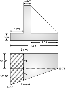
Fig. 4.44: Upward pressure distribution diagram
Resultant pressure
(1) At A = 148.6 – 10 = 138.6 kN/m2 ()
(2) At B =119.3 – 10 = 109.3 kN/m2 ()
Shear force = Area of triangle + Area of rectangle
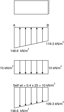 = (1.2) (138.6 – 109.3) + 1.2 × 109.3
= 148.7 kN
Factored shear force
Vu = 1.5 × 148.7 = 223.12 kN
BM = (Area of rectangle × c.g. Dist.)
+ (Area of triangle × c.g.dist)
M = 1.2 × 109.3 × + (1.2)
× (138.6 – 109.3) × 1.2
= 92.76 kN.m
Mu = 1.5 × 92.76= 139.14 kN-m
Check for depth:
Maximum BM = 139.14 kNm
Mulim = 0.138 fck bd2
Mu lim = BM max
0.138 fck bd2 = 139.14 × 10⁶
0.138 × 20 × 1000 × d2 = 139.14 × 10⁶
d = 224.5 mm
Assuming cover =40 mm Fig. 4.45: Resultant pressure
Diagram
Drequired = 224.5 + 40 = 264.5 mm <Dassumed (400 mm)
Providing D = 400 mm
d = 400 – 40 = 3600 mm
Area of steel reinforcement:
Ast = b.d
= × 360 × 1000=1146 mm2
Check for Ld
Ld = + L0 For M20 and Fe 415 Ld=
Ld = 47 L0 = d = 360 mm
47 + 360 20.92 mm
 Assuming 16 mm bars
Spacing = = 175.31 ≅ 170 mm < 3d or 300.
 Providing 16 mm bars @ 170 mm c/c
Provide at bottom because
Area of distribution steel = b × D= × 1000 × 400 = 480 mm2
 Assuming 8 mm bars
Spacing = < 3 d or 300=104 mm ≅ 100 mm
 Providing 8 mm bars @ 100 mm c/c
Check for shear
v = = = 0.62
 Pt = Ast(pro =
= = 1182.72 mm
=
= 0.33
From IS page 73 table (19)
Pt | c |
0.25 | 0.36 |
0.5 | 0.48 |
c = 0.36 +
= 0.3984 N/mm2
v > c
Design of shear reinforcement is required.
c ≯ cmax
Design of shear reinforcement:
 vus = vu – c bd = 223.12 × 10³ – 0.39 × 1000 × 360 = 82.7 × 10³ N
Assuming 8 mm 5 legged stirrups.
(1) sv = = = 4.28mm (Not feasible)
(2) sv = = =226 mm
(3) sv = 0.75 d or 300 mm
Taking least value = 226 mm
Spacing = 220 mm
 Providing 8 mm 5 lugged stirrups @ 220 mm c/c.
Final provision:
 (1) Main steel = 16 mm @ 170 mm c/c
 (2) Distribution steel = 8 mm @ 100 mm c/c
 (3) Stirrups = 8 mm 5 legged stirrups @ 220 mm c/c.
Design of Heel slab:
(1) Base press
(2) Self weight = 0.4 × 25 = 10
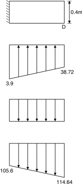
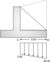
Fig. 4.46 Fig. 4.47
(3) Earth press
(a) At left edge = 6.6 × 16 = 105.6 (b) At right edge = 7.15 × 16 = 114.64
(4) Resultant press
(a) At left edge = 113.19 – 10 – 1056 = – 2.49 kN/m2
(b) At right edge = 38.72 – 10 – 11464 = – 85.52 kN/m2
Taking maximum value
w2 = 85.52 kN/m2
Maximum SF, v = 0.6 w2l=0.6 × 85.52 × 3.5
l = spacing of counter fort = 3.5 m
= 179.59
Factored S.F.
vu = 179.59 × 1.5 = 269.38 kN
Max BM =
M = 85.52 =87.3 kNm
Factored B.M., Mu = 1.5 87.3 = 130.95 kNm
Check for depth:
Mu = Mu(lim) 130.95 106 = 0.138 bd2 fck
130.95 106 = 0.138 1000 d2 20
d = 217.84 mm D = 217.84 + 40=257.84 Dassumed (400 mm)
Providing D = 400 mm d = 400 – 40 = 360 mm
Area of steel:
Ast = bd
= 1000 360 mm=1074.5 mm2
Check for Ld :
Ld + L0
For Mw and Fe415 Ld = 47
L0 = d = 360 mm 47 + 360
18 mm
Assuming 16 mm bar
Spacing = =187 mm 3d or 300
Providing 16 mm @ 180 mm c/c
Distribution steel:
Ast = b D= 1000 400=480 mm2
Assuming 8 mm bars
Spacing = =104 ≅ 100
Providing 8 mm @ 100 mm c/c
Check for shear:
V = = =0.74 N/mm2
pt = , Ast(prov) = = 1117 mm2
= =0.31
| M20 – c |
0.25 | 0.36 |
0.5 | 0.48 |
|
|
c = 0.36 + (0.31 – 0.25)=0.38 N/m2
For slabs k = 1 (Pg. - 72)
v kc
Design of shear reinforced is required
Design of shear reinforcement:
Vus = Vu – c bd=269.38 103 – 0.38 1000 360=132.58 103 N
Assuming 8 mm 5 legged stirrups
(I) SV = ==246.39
(II) SV = ==226.85
(III) SV = 0.75d or 300=0.75 360 or 300=270
Taking the least value=226.85≅220 mm
 Providing 8 mm diameter 5 legged stirrups @ 220 mm c/c
Example 4.6.6 :Suggest suitable proportions for a counterfeit retaining wall to support difference in ground elevation of 9m, the depth of foundation may be taken as 1.5 m below ground level, with a safe bearing capacity of 160 kN/m2. Assume a level backfill with a unit weight of 16 kN/m3 and an angle of shearing resistance of 30 . Also, assume coefficient of friction = 0.5 between soil and concrete. Check the stability of the wall.
Ans.:
Step 1: Proportioning of retaining wall :
H2 = 9 m, qo = 160 kN/m2, = 30, r = 18 kN/m3
Coefficient of active earth pressure Ke = = =
Depth of foundation = 1.5 m
Total height of retaining wall H = 9 + 1.5 = 10.5 m
Base width = 0.5 H to 0.6 H = 0.5 10.5 to 0.6 10.5
= 5.25 m to 6.3 m
Let base width b = 5.5 m
Toe projection = = = 1.83 m 1.9 m
Width of counter forts = 0.03 H to 0.06 H = 0.03 10.5 to 0.06 to 10.5
= 0.315 m to 0.63 m
Let width of counter fort = 0.5 m
Thickness of stem = thickness of base slab = = = 0.42
Say thickness of stem = 420 mm
From calculations above, selected section is shown in Fig. 2.48
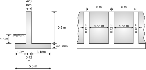
Fig. 4.48
Step 2: Stability check :
Sr. No. | Force | Magnitude (kN) | (m) | M (kN-m) |
1. | W1 = weight of back fill | 4.58 10.5 18 = 856.62 | 5.5 – = 3.91 | 3349.38 |
2. | W2 = weight of stem | 0.42 10.5 25 = 110.25 | 1.9 + = 2.11 | 232.62 |
3. | W3 = weight of base slab | 0.42 5.5 25 = 57.75 | = 2.75 | 158.81 |
|
| W = 1024.62 |
| M = 3740.81 |
Overturning moment = Ka= 18 (10.5 + 0.42)3 = 1302.17 kN-m
Factor of safety against overturning
= = 2.58 > 1.4 Hence ok
Sliding force pH = Ka= 10.922 = 357.74 kN
Resisting force = (0.9W1 + W2 + W3)
=0.5 (0.9 856.62 + 110.25 + 57.75) = 469.479 Kn
Factor of safety against sliding = = 1.31 < 1.4
Hence, shear key is required. Provide a shear key of depth 420 mm.
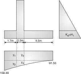
Example 4.6.7: Design of counter fort Retaining wall for following :
(1) Height of vertical wall above GL = 7.5 m
(2) The earth leveled with the top (No surcharge)
(3) Density of earth fill = 16 kN / m3
(4) Angle of repose = = 28
(5) Foundation depth below G.L = 2m
(6) Safe bearing capacity of soil = 200 kN/m2
(7) Counter fort spacing = 3.5m
(8) Coefficient of friction = = 0.45 (25 Marks)
Ans.:
Assuming M20 and Fe415.
Given: height of wall above G.L = 7.5 m
Depth below GL = 2m, Total height of wall = 9.5 m = H,
Density of soil = w = 16 kN/m3
Angle of repose = = 28; M20 and Fe415
(1) Preliminary section:
(1) Total height of wall, H = 9.5 m
(2) Base width = 0.6 H to 0.7 H = 0.6 9.5 to 0.7 9.5 = 5.7 to 6.65 m
Assuming B = 6m
(3) Toe width = to or = to or =2 to 1.5 or 1.58
Assuming the width = 1.7 m
(4) The following thickness of vertical wall = 0.3 m
(5) Width heel slab = 6 – 1.7 – 0.3 = 4m
(6) Thickness of base slab = 2lH or 4 l
l = spacing of counter fort = 3.5 m
Thickness of base slab = 2 3.5 9.5 or 4 3.5 =66.5 cm or 43.5 cm
Assuming thickness of base slab = 0.5m
(2) Forces on retaining wall:
(i) Earth pressure
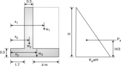
Fig. 4.49: Loads in retaining wall
Pa = Ka w H2 Ka =
= =0.36
Pa = 0.36 16 (9.5)2 – = 3.16 m=259.92 kN
(ii) Self weight:
(1) Weight of soil up to top, w1 = area density=4 9 16 = 576 kN
x1 = + 0.3 + 1.7=4 m
(2) Weight of vertical wall
w2 = 0.3 9 25 = 67.5 kN x2 = + 1.7 = 1.85 m
(3) Weight of base slab,
w3 = 6 0.5 25 = 75 kN x3 = = 3 m
w = w1 + w2 + w3 = 576 + 67.5 + 75 = 718.5 kN
wx = w1 x1 + w2 x2 + w3 x3=(576 4) + (67.5 1.85) + (75 3)
= 2653.88 kN.m
(3) Check for stability:
(i) Check against overturning
Overturning moment = 1.2 Pa=1.2 259.92 =987.7 kN.m
Restoring moment = 0.9 wx=0.9 2653.88=2388.49 kN.m
Restoring moment > overturning moment
Safe against overturning.
(ii) Check against sliding
Sliding force = 1.4 Pa = 1.4 259.92=363.89 kN
Restoring force = 0.9 w=0.9 0.45 718.5=290.99 kN
Restoring force ≯ sliding force
Not safe in shear
Providing shear key
(iii) Check against base pressure:
Pmax = < SBC V = w1 + w2 + w3=718.5
e = – Z
Taking moment @ Toe
MToe = w1 x1 + w2 x2 + w3 x3 – Pa
= 2653.88 – 259.92 =1830.8 kN-m
Z = == 2.55 m
e = – 2.55=0.45 m
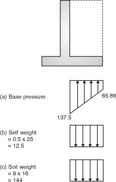
Pmax = =173.64 kN/m2 ≯ SBC (200 kN/m2) …O.K.
Pmin = > 0=> 0=65.86 > 0 OK
(4) From Similarity of triangles:
=
y2 = 77.23
Total = y1 + y2 = 65.86 + 77.23
= 143.04
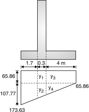 =
=
y4 = 71.85
Total = y3 + y4
= 65.86 + 71.85
= 137.7
Fig.4.50: Pressure distribution diagram
(5) Design of Counterfort:
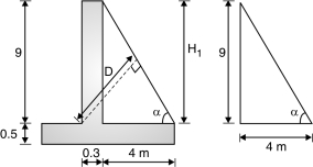
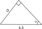
Fig. 4.51: Geometry of retaining will
Tan = = 66.03
= 90 – =23.97 sin =
 sin 66.03 =
D = 3929.43
D = 4000 mm
Assuming cover = 100 mm
Fig. 4.52
d = 4000 – 100=3900 mm
Load transferred by vertical wall = Horizontal pressure Spacing of counter fort
= Ka w H1 l H1 – height of vertical wall
= 0.36 16 9 3.5=181.44 kN/m
F = w1 H/2=181.44 =816.48 kN
Bm = = =2449.44 kN.m
Factored S.F = Vu = 1.5 816.48 =1224.72 kN
Factored BM = Mu = 1.5 2449.44 =3674.16 kN
For varying depth section
Vu (design) = Vu – =1224.72 103–= 805.8 103N
Check for depth:
Mu = Mu (lim) 3674.16 106 = 0.138 bd2 fck
3674.16 106 = 0.138 400 (d2) 20
d = 1824.29 mm < dsub
Safe
Providing D = 4000 mm d = 3900 mm
Area of steel:
Ast = bd
=
= 2708.17 mm2
Check for development length
 Ld + Lo
For M20 and Fe 415 Ld = 47
47 + 3900
179.9 mm
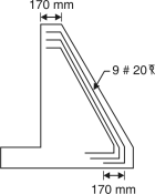
Provide 20 mm bars
Number of bars =
= 8.6 ≅ 9 bars Fig. 4.53
(a) The tension between counter fort and vertical wall
(Design of horizontal stirrups)
For 1m height of counter fort
Tension T = Pressure on vertical wall spacing 1m=Ka WHl 1
= (0.36 16 9) 3.5=181.44 kN
Tu = 1.5 181.44 = 272.16 kN
Assuming sp of stirrups = 200 mm c/c
For 1m height number of stirrups = 5
Asv = ==150.76 mm2
(b) Check for shear for horizontal stirrups
v = = = 0.52 N/m2
Pt % = = = 0.18
From table 19, pg. 73
c = 0.30 N/m2 v > c
Design of shear reinforcement is required.
Vus = Vu (design) – c bd
= 805.8 103 – 0.30 400 3900
= 337.8 103 N
Sv = 200 =
 Asv = 47.97 mm2
Total Asv = 150.76 + 47.97=198.73 mm2
Assuming 2 legged stirrups
2 2 = 198.73
= 11.24
Providing 12mm 2 legged stirrups
@ 200 mm c/c from base to
= 4.5 mand @ 400 mm c/c from 4.5 m upto top.
Direct tension between heel slab and
Counterfort (vertical stirrups)
Resultant:
At left edge = 137.5 – 12.5 – 144
= – 19
At right edge = 65.86 – 12.5 – 144
= – 90.64kN/m
Taking greater value
T = maximum pressure in heel slab spacing of counter fort
=90.64 3.5 1 = 317.24 kN
Tu = 1.5 317.74 = 475.86 kN
Number of stirrup
S = = force taken by one stirrup
Assuming 12 mm diameter 2 legged stirrups
Number of stirrups = = 5.8 ≃ 6 /m
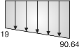
Fig. 4.54: Base pressure diagram
Spacing = = 166.66≃ 160 mm c/c
Providing 12 mm dia. 2 legged stripes @ 160 mm c/c.
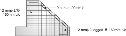
Fig. 4.55: Reinforcement details
Example 4.6.8: Design a counterfort retaining wall for the following data
1. Height of steam above GL = 8 m
2. Earth fill level with top.
3. Density of earth fill = 16 kN/m3
4. The foundation depth below the GL = 1.7 m
5. Angle of repose, = 30
6. S.B.C. Of soil = 200 kN/m2
7. Counter fort spacing = 3.5 m c/c.
8. Coefficient of friction between the soil and slab = 0.5
Assuming M20 and Fe415
1. Height of stem above GL = 8m
2. Foundation depth below GL = 1.7 m
3. Total height of step = 8 + 1.7 = 9.7 m
4. = 30
5. w = 16 kN/m3
6. = 0.5
Ans.:
1. Preliminary dimensions:
(i) Total height of wall = 9.7 m
(ii) Base width = 0.6 H to 0.7 H
= 0.6 9.7 to 0.7 9.7 = 5.82 to 6.79 B = 6.5 m
(iii) Toe width = to or
= to or = 2.16 to 1.625 or 1.61 = 1.7 m
(iv) Thickness of vertical wall = 0.3 m
(v) Width of heel slab = 6.5 – 1.7 – 0.3 = 4.5 m
(ii) Thickness of base slab = 2lH or ul=2 3.5 9.7 or 4 3.5
=67.9 or 43.6 cm
Assuming thickness of base slab = 0.5 m
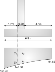
(2) Forces on retaining wall:
(i) Earth pressure
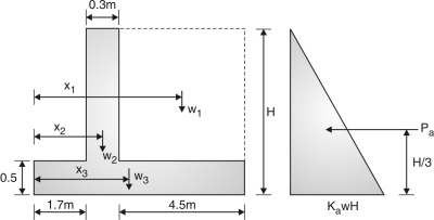
Fig.4.55: Forces on retaining wall
Pa = KawH2 Ka = = = 0.33
Pa = 0.33 16 (9.7)2 = 248.39
= = 3.23 m
(ii) Self weight
(1) Weight of soil up to top,
w1 = area density =4.5 9.2 16 = 662.4 kN
x1 = + 0.3 + 1.7 = 4.25 m
2. Weight of vertical wall
w2 = 0.3 9.2 25 = 69 kN x2 = + 1.7 = 1.85 m
3. Weight of base slab
w3 = 0.5 6.5 25 = 81.25 kN
X3 = = 3.25 m w = 662.4 + 69 + 81.25 = 812.65 kN
wx = w1x1 + w2x2 + w3x3 = 3206.91 kN-m
(3) Check for stability:
(i) Check against overturning
Overturning moment = 1.2 Pa=1.2 248.39 3.23 = 962.76 kN-m
Restoring moment = 0.9 wx=0.9 3206.91= 2886.22 kN-m
Restoring moment > overturning moment
2886.22 > 962.76
Safe against overturning.
(ii) Check against sliding
Sliding force = 1.4 Pa = 1.4 248.39 = 347.75 kN
Restoring force = 0.9 w=0.9 0.5 812.65 = 365.69
Restoring force > sliding force
Safe in shear
(iii) Check against base pressure
Pmax = < SBC M = w + w2 + w3 = 812.65
e = – Z
Taking moment (a) Toe
MToe = w1x1 + w2x2 + w3x3 – Pa=3206.91 – 248.39
= 2404.61 kN-m
Z = = = 2.96 m e = – Z = 0.29 m
Pmax = =158.49 SBC (200 kN/m2)
Pmin = > 0 = 91.55 > 0 OK.
(4) Design of vertical wall:
(i) Vertical wall is designed as vertical slab spanning between counterfort.
Pressure intensity at bottom of wall = KawH1=0.33 16 9.2 = 48.57
Maximum SF = 0.6 w1l= 0.6 48.57 3.5
= 102 kN
Factored SF = 1.5 102 = 153 kN
Maximum BM = =
= 49.58 kN-m
 Factored BM = 1.5 49.58
= 74.37 kN-m
(ii) Check for depth
Max BM = Mulim
106 74.37 = 0.138 bd2 fck
106 74.37 = 0.138 1000 d2 20
d = 164 mm
Assuming cover 40 mm
Drequired = d + 40 = 164 + 40
= 204 < dassumed< 300 mm
Providing, D = 300 mm D = 260 mm Fig. 4.56: Pressure distribution
(iii) Area of steel:
(a) Area of main steel = – bd
= 0.5 1000 260
= 850.34 mm2
ld + lo ld = 47 for M20 an felus
47 + 260 = 15.87 mm
Providing 12 mm diameter bars
Spacing = 133 < 300 or 300 OK
Providing 12 mm bars @ 130 mm c/c from base to 4.6 m and Providing 12 mm bars @ 200 mm c/c from 4.6 m up to top of wall.
(b) Area of distribution steel = b D= 1000 300 = 360 mm2
Assuming 8 mm bar
Spacing = =139.63 5d or 450 mm
Providing 8 mm @ 130 mm c/c
(iv) Check for shear
v = = = 0.59 N/mm2
Pt% = = = 0.33
Page 7.3 table -19
Pt % | c |
0.25 | 0.36 |
0.5 | 0.48 |
c = 0.36 + (0.33 – 0.25)
c = 0.39 N/m v > c
Design of shear reinforcement is required.
Design shear force = Vus
Vus = Vu – c bd = 153 103 – 0.39 1000 260
= 51.6 103 N
Sv =
Assume 8 mm 5 legged stirrups
(1) Sv = = 457.2 mm
(2) Sv = = = 226.85
(3) Sv = 0.75dor 300 mm = 0.75 260 or 300 mm = 195 mm
Taking least of the three
= 195 mm ≅ 190 mm
Providing 8mm stirrups @ 190 mm c/c
Final provision:
 (1) Main – 12 = mm@ 130 mm c/c up to 4.6 m from base.

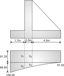
Fig. 4.57: Pressure distribution
= 12 mm @ 260 mm c/c 4.6 to top of wall
 (2) Distribution = 8 mm @ 130 mm c/c
 (3) stirrups = 8mm 5 sagged stirrups @ 190mm c/c
(4) Design of toe slab
(5) Design of toe slab
Designing as cantilever fixed at the face of vertical wall.
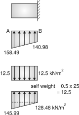 From similar △ property
=
y2 = 49.43
Total ordinate = y1 + y2 = 91.55 + 49.43 = 140.98
Upward pressure:
Resultant pressure
(1) At A = 158.49 – 12.5 = 145.99 kN/m2
(2) At B = 140.98 – 12.5 = 128.48 kN/m2
Shear force = Area of triangle + Area of rectangle
= (1.7) (145.99 – 128.48) + 1.7 128.48
= 233.29 kN Fig.4.58: Resultant
Pressure diagram
Factored S.F. = 1.5 233.39 = 349.95 kN
B. M. = (Area of rectangle C.G. Distance) + (Area of triangle C.G. Distance)
M = 1.7 128.48 + (1.7) (145.99 – 128) 1.7 = 202.52 kN-m
Mu = 202.52 1.5 = 303.78 kN-m
Check for depth:
Max BM = Mulim
303.78 106 = 0.138 bd2 fck
303.78 106 = 0.138 1000 d2 20
d = 331.76 mm
D = 331.76 + 40 = 371.76 mm
<Dassumed< 500 mm
Providing D = 500 mm And d = 460 mm
Area of steel:
Ast =
Bd = 1000 460
Ast = 2012.74 mm2 Ld + lo
47 + 460 28.25
Assuming 20 mm  bars
bars
Spacing = = 156.08
≅ 150 mm 3d or 300 mm
 Providing 16 nos. 20 mm bars @ 150 mm c/c.
Area of Distribution steel = bD …(1)
= 1000 500 = 600 m2
 Assuming 8mm bars
Spacing = = 83.77
 Providing 8mm @ 80mm c/c
Check for shear From IS page 73 table 19.
Pt % | Cc |
0.25 | 0.36 |
0.5 | 0.48 |
v = = = 0.76 N/mm2
Pt % = = = 0.455
c = 0.36 + (0.455 – 0.25) = 0.458 N/mm2= c
∴ Design of shear reinforcement is necessary.
Design of shear reinforcement:
Vus = Vu – c bd = 349.95 103 – 0.458 1000 460
= 139.27 103 N
 Assuming 8 mm 5 legged stirrups
 (1) = = 299.71 300 mm
(2) Sv = =
= 226.85 mm
(3) Sv = 0.75 d or 300 mm = 0.75 460 or 300
= 300 mm
Taking least value = 226 mm
Spacing = 220 mm
(6) Design of heel slab:
It is a continuous slab spanning between counter forts. ...Ans.
Fig.4.59 Pressuredistribution
From similar
=
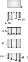 y4 = 46.34
Total = y3 + y4 = 91.55 + 46.34 = 137.89
Self weight = 0.5 25 = 12.5
Weight of soil = 9.2 16 = 147.2
Resultant at left edge = 137.89 – 12.5 – 147.2
= – 21.81 kN/m2
At right edge = 91.55 – 12.5 – 147.2
= – 68.15 kN/m2
Taking maximum value,
w2 = 68.15 kN/m2
Maximum SF, V = 0.6 w2l = 0.6 68.15 3.5
= 143.115 kN
Factored SF = 143.1151.5 = 214.67 kN Fig.4.60: Base pressure
Check for depth:
Maximum BM =
M = = 69.57 kN-m
Factored BM, Mu = 1.5 69.57 = 104.35 kN-m
Mu = Mu(lim) 106 104.35 = 0.138 fck bd2
104.35 106 = 0.138 20 1000 d2
d = 194.44 < dassumed.
Providing D = 500 mm d = 460 mm
Area of steel:
Ast = bd
= 1000 460 =647.53 mm2
Ld + l0
For M20 and Fe 415 =Ld = 47
L0 = d = 460 mm 47 + 460
20.12 mm
Assuming 12 mm bars Spacing = = 174.66 < 3d or 300 mm
Providing 12 mm @ 170 mm c/c
Distribution steel:
Ast = b D = 1000 500 = 600 mm2
Assuming 8 mm  bars
bars
Spacing = = 130
 Providing 8 mm @ 130 mm c/c
Check for shear reinforcement:
v = = = 0.466 N/mm2
Pt % = = = 0.14
c = 0.28 N/m2 for slab k = 1, kc = 0.28
v = c
Design of shear reinforcement is required.
Design of shear reinforcement:
Vus = Vu – c bd = 214.67 103 – 0.28 1000 460 = 85.87 103 N
Assuming 8 mm 5 legged stirrups.
(i) sv = = = 446.98 mm
(ii) sv = = = 226.85 mm
(iii) sv = 0.75 d or 300 = 0.75 460 or 300 = 345 or 300
Taking least value = 226.85 ≅ 220 m,
Providing 8 mm 5 legged stirrups @ 220 mm c/c
Final provisions:
 1. Main steel = 12 mm bars @ 170 mm c/c
 2. Distribution steel = 10 mm bars @ 130 mm c/c
 3. Stirrups = 8 mm 5 legged stirrups @ 220 mm c/c
(7) Design of counter fort:
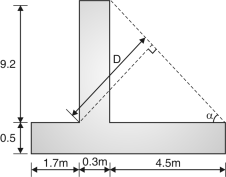 tan = =63.93
= 90 – 63.93 = 26.07
Sin =
Sin 63.93 4.8 = D
D = 4.31
Assuming D = 4400 mm
Assuming cover = 100 mm
d = 4400 – 100 = 4300

Load transferred by vertical wall
= horizontal pressure spacing of counter fort
= Ka W H1l
= 0.33 16 9.2 3.5 = 170.01 kN/m
SF = = = 782.07 kN Fig.4.61: Geometry of
Retaining wall
Factored SF = 1.5 782.07 = 1173.11 kN
BM = = = 2398.27 kN.m
Factored BM = Mu = 1.5 2398.27 = 3597.41 kN-m
For varying depth section.
Vu (design) = Vu –
= 1173.11 103 – = 763.8 103 N
Check for depth:
Mu = Mulim
3597.41 106 = 0.138 fck bd2
3597.41 106 = 0.138 20 400 d2
d = 1805.13 < dassumed safe
Providing D = 4400 mm and d = 4300
Area of steel:
Ast = bd
= 4300400
=2387.05 mm2
Ld + L0
For M20 and Fe415 = Ld = 47
 L0 = d = 4300 mm
47 + 4300
191.69
Provide = 20 mm bars
Number of bars = = 7.59 ≅8 bars
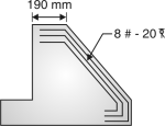
Fig.4.62: Reinforcement
The tension between counter fort and vertical wall
(Design of horizontal stirrups)
For 1 m height of counter fort
Tension = T = Pressure on vertical wall Spacing l
= KawHl1 = 0.33 16 9.2 3.5 1 = 170.01 kN
Tu = 1.5 170.01 = 255.02 kN
Assuming spacing of stirrups = 200 mm c/c
For 1 m height number of stirrups = 5
Asv = = = 141.27 mm2
(b) Check for shear for horizontal stirrups
v = == 0.44 N/m2
Pt % = = = 0.15
From table 19, Pg- 73
c = 0.28 N/m2 v > c
Design of shear reinforcement is required.
Vus = Vu design – c bd
=763.8 103 – 0.28 400 4300 = 282.2 103 N
Sv =
200 =
Asv = 36.35
Total Asv = 141.27 + 36.35 = 177.62 mm2
Assuming 2 legged stirrups
2 2 = 177.62
= 10.63
Providing 12 mm 2 legged stirrups @ 200 mm c/c from base to = 4.6 m
And @ 400 mm c/c from 4.6 m upto top
Direct tension between heel stab and counter fort (vertical stirrups)
T = Maximum pressure in heel slab Spacing of counter fort
T = 90.64 3.5 1 = 317.24 kN
Tu = 1.5 317.24 = 475.86 kN
Number of stirrups =
Assuming 10 mm 2 legged stirrups
Number of stirrups =
= 8.39 ≅ 9 m
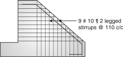 Spacing = = 111.11 mm ≅110 mm


