UNIT 5
Liquid Retaining Structures
A water tank is used to store water to tide over the daily requirements.
Water tanks can be classified under three categories :
(i) Tanks resting on ground,
(ii) Elevated tanks supported on staging and
(iii) Underground tanks.
Depending in shape, water tanks are classified as
(i) Circular tanks,
(ii) Rectangular tanks
(iii) Spherical tanks,
(iv) Intze tanks and
(v) Circular tanks with conical bottoms
Permissible stresses in concrete and shear for various grades of concrete:
Plain Concrete Structures
Plain concrete members of RCC water tanks should be designed to withstand structural failure by allowing tension in plain concrete.
It should be in accordance with permissible limits for tension in bending as per IS: 456.
Permissible Stress in Concrete
(a) For resistance to cracking:
Table 5.2.1: Permissible concrete stress for Resistance to Cracking
Grade of Concrete | Permissible stress | Shear = (n/mm2) | |
Direct Tension (ct) (N/mm2) | Tension due to bending (ct) (N/mm2) | ||
M15 | 1.1 | 1.5 | 1.5 |
M20 | 1.2 | 1.7 | 1.7 |
M25 | 1.3 | 1.8 | 1.9 |
M30 | 1.5 | 2.0 | 2.2 |
M35 | 1.6 | 2.2 | 2.5 |
M40 | 1.7 | 2.4 | 2.7 |
(b) For strength calculations:
If the calculated shear, stress in concrete exceeds permissible value, uniforcement along with diagonal compression in concrete should be provided.
(a) For resistance to cracking
Table 5.3.1: Permissible Stress in Steel Reinforcement for Strength Calculations
Sr. No. | Types of stress in steel reinforcement | Permissible stress (N/mm2) Plain round mild, steel bars as per IS : 482 (Part I) 1966 | HYSD bars as for IS : 1139-1966 |
1. | Tensile stress in members under direct tension (s) | 115 | 150 |
2. | Tensile stress in member in bonding (st) |
|
|
| (a) On liquid retaining force of members. | 115 | 150 |
| (b) On force away from liquid for members less than 225 mm. | 115 | 150 |
| (c) In force away from liquid for members 225 mm or more thick. | 125 | 190 |
3. | Tensile stress in shear reinforcement (sv) |
|
|
| (a) for members less than 225 mm thickness. | 115 | 150 |
| (b) for members 225 mm or more in thickness | 125 | 175 |
4 | Compressive stress in columns subjected to direct load (sc) | 125 | 175 |
(b) For strength calculations
Table 5.3.2: Permissible Steel Stresses
(Elastic Method for Strength Calculating)
Condition | Class of exposure | Permissible plain bars | Stress (N/mm2) Deformed bars |
Direct Tension | A | 85 | 100 |
Flexural Tension and shear | B | 175 | 130 |
Compression | A and B | 125 | 140 |
(i) Minimum reinforcement in water tank:
(1) IS codes permit a minimum of 0.3% of concrete section in each direction for sections up to 100 mm thick.
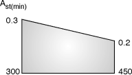
(2) For sections with thickness between 100 mm and 450 mm, minimum steel in each direction may be reduced from 0.3% for 100 mm thick section to 0.2% for 450 mm.
(3) In concrete sections of 225 mm or greater, two layers of steel shall be placed one near each face of the section to make up minimum steel.
(4) In floor, labs resting directly on firm ground, the percentage of steel may be reduced. In no case, minimum percentage of steel be less than 0.15% of the concrete section.
(ii) Causes of cracking and its controlling :
Causes of cracking:
1. Direct tension, Bending tension, and shear in concrete
2. Drying shrinking or temperature change
Controlling of cracking:
1. For liquid faces of parts of members in contact with liquid, the minimum cover to all reinforcement should be 25 mm or diameter of main reinforcement, whichever is greater.
For sea water, it may increase by 12 mm but need not be considered in calculations.
2. For faces away from liquid, cover should be same as provided for other RC sections.
(a) Movements joints
(b) Construction joints
(c) Temporary open joints
(a) Movements joints:
All movement joints are necessarily flexible joints,
(i) Contraction joint,
(ii) Expansion joint and
(iii) Sliding joint
(i) Contraction joint :
(1) It accommodates contraction of concrete.
(2) It may be a complete contraction joint (Fig. 4.5.1(a)) or a partial contraction joint (Fig. 4.5.1 (b)).
(3) In both cases, initial gap is absent at joint,
(4) In complete contraction joint, water bar is inserted.
(5) In partial contraction joint, mouth of joint is filled with joint sealing compound.
(6) The commonly used materials for joint realing are asphatt, bitumen or coal for pitch with or without fillers.
(ii) Expansion joint :
(i) It accommodates expansion or contraction of structures.
(ii) Initial gap is filled with a joint filler.
(iii) Joint fillers are compressible sheet used as spaces.
(iii) Sliding joint:
(i) It is a movement joint having complete discontinuity in reinforcement as well as concrete.
(ii) A special provision is made to facilitate relative movement.
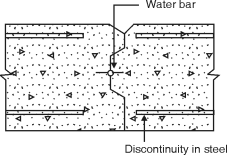
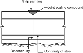
(a) Complete contraction joint (b) partial contraction joint
Fig. 5.5.1
(b) Construction joints:
(1) It is introduced in concrete for convenience in construction.
(2) It is a rigid joint.
(3) The portion and arrangement of these joints should be derived by
Engineer.
(c) Temporary Open Joints:
(1) It is a gap temporarily left between concrete of adjoining parts of a structure.
(2) The width of gap should sufficient so as to prepare the sides for filling.
Ex. 5.6.1: A circular water tank of 8 m diameter is 4.5 m high. The floor slab is monolithic with the walls. Design the wall of the tank.
Soln.:
Depth of tank = 4.5 m, Diameter of tank = 8 m
Assume a free board of 200 mm
Total height of tank H = 4.5 + 0.2 = 4.7 m
Unit weight of water = 9.8 kN/m3
Assume M25 concrete and Fe415 steel
Permissible tensile stress in steel = 150 N/mm2 = st
Permissible tensile stress in concrete = 1.3 N/mm2
cbc = 8.5 N/mm2
Modular ratio, m = = 11
Design constants:
n = = = 0.384
j = 1 – = 1 – = 0.872
k = cbc j n = 8.5 0.872 0.384 = 1.423
Design for Cantilever Action:
The height ‘h’ above base up to which cantilever action exist is give by h = or 1m whichever is more.
h = = 1.567 m
Cantilever moment = H h = 9.8 4.7 1.567
= 18.85 kN-m.
Depth of balanced section d = = = 115 mm
Let d = 115 = 153.35 mm
Let us provide d = 155 mm and total thickness = 190 mm
Ast = = = 929.76 mm2
Using 10 mm bars
s = = 80.11 mm
= 84.47 mm
Provide 10 mm bars @ 80 mm c/c near inner face, keeping a clear cover of 30 mm.
Cultural alternate bars at a height of 1.56 m and spacing of 160 mm is available in top 3.14 m height.
Design for hoop action:
Maximum hoop tension is considered at 1.56 m height.
T = (H – h) = 9.8 (4.7 – 1.56) = 123.09 kN
Ash = = 820.58 mm2
Using 10 mm bars,
Spacing = 1000 = 95.71 mm
Provide 10 mm bars @ 95 mm c/c.
Check for tensile stress in concrete:
Ash = 1000 = 826.73 mm2
ct =
=
= 0.61N/mm2 < 1.3 N/mm2
Hence OK.
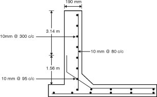 Provide a spacing of 100 mm for 1.56 m height and 300 mm spacing above 1.56 m height .
Fig. P. 5.6.1: Reinforcement details
Ex. 5.6.2: Design a vertical wall and base of flat base circular water tank with flexible joint with base. The capacity of tank is 1000 kJ, the depth of water tank is restricted to 4.5 m, and the tank base is resting on ground. Use M25 concrete and Fe415 steel.
Ans.:
Capacity of tank = 1000 kJ = 1000 m3 , Depth of tank = 4.5 m
Assume diameter of tank = D ,
D2 4.5 = 1000, D = 16.82 m 17 m
Free board = 200 mm,
Total height of tank H = 4.5 + 0.2 = 4.7 m
Unit weight of water r = 9.8 kN/m3
Permissible tensile stress in Fe415 steel = 150 N/mm2
Permissible tensile stress in concrete = 1.3 N/mm2
Maximum hoop tension T = rH
= 9.8 4.7
= 391.51 kN/m height of base.
s = 150 N/mm2
Area of steel for hoop tension Ash =
= 610.06 mm2
Using 16 mm bars, spacing = 1000 = 77.03 mm
Provide 16 mm bars @ 75 mm c/c.
Ash provided = 162 = 2680.8 mm2/m height.
Increase spacing to 150 mm at a height of 1.6 m from base.
Thickness of wall:
Max hoop tension T = 391.51 kN
Permissible stress in tension = 1.3 N/mm2
Modular ratio m = = = 11
Equivalent area of concrete /m height = 1000 t + (m – 1) Ash
c =
1.3 = 1300 t + 41820.48 = 391510
1300 t = 349689.52
t = 268.99 mm tprovide = 270 mm
Vertical steel:
Pmin = 0.3%
Prequired = 0.3 – 0.1 = 0.25 %
Ast (required) = 270 1000 = 675 mm2
Use 10 mm bars spacing = 1000 = 116 mm
Provide 10 mm bars @ 110 mm c/c.
Base slab:
Ast minimum = 150 1000 = 450mm2
provide half reinforcement.
Near each face
Ast = 225 mm
Use 8 mm bars, s = 82 = 223 mm
Provide 80 mm bars @ 220 mm c/c on both faces in both directions.
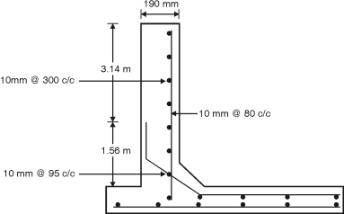
Fig. P. 5.6.2: Reinforcement diagram
Ex. 5.6.3: Design a circular tank for a capacity of 500 kl with flexible joint at the base. Use (i) mild steel reinforcement (ii) HYSD bars.
Soln.:
Capacity of tank = 500 kl = 500 m3 , Depth of tank = 4 m (Assume),
Assume diameter of tank = D
D2 4 = 500 D = 12.61 m 13 m
Free board = 400 mm
Total height of tank H = 4 + 0.2 = 4.2 m
Unit weight of water r = 9.8 kN/m3
Permissible tensile stress in Fe415 steel = 150 N/mm2.
Permissible tensile stress in concrete = 1.3 N/mm2
Maximum hoop tension T = rH = 9.8 4.2
= 267.54 kN/m height at base
s = 150 N/mm2
Ash for hoop tension Ash = = 1783.6 N/mm2
Use 16 mm bars
Spacing = 1000 = 112.73 mm
Provide 16 mm bars @ 110 mm c/c
Ash provided = 162 = 1827.83 mm2
Increase the spacing to 220 mm at a height of 1.5 m from base.
Thickness of wall:
Maximum hoop tension T = 267.54 kN ,
Permissible stress in tension = 1.3 N/mm2
Modular ratio for M25concrete
M = = = 11
Equivalent area of concrete/m height = 1000t + (m – 1) Ash
c =
1.3 =
t = 183.86 mm 185 mm
Vertical steel:
Pt min = 0.3%
Pt (required) = 0.3 – 0.1 = 0.275 %
Ast (required) = = 510 mm2
Use 8 mm bars s = 1000 = 98.5 mm
Provide 8 mm bars @ 90 mm c/c
Base slab:
Load gets transformed to ground directly. Hence, a nominal thickness of 150 mm can be provided. Minimum reinforcement in both directions is provided.
Ast (minimum) = 185 1000 = 555 mm2
Provide half reinforcement near each face.
Ast = 218 mm2
Use 8 mm bars s = 1000 = 230.57 mm
Provide 8 mm bars @ 230 mm c/c on both faces in both directions.
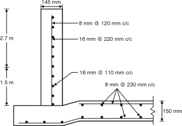
Fig. P. 5.6.3
Ex. 5.6.4: Design the wall of a circular tank of 7 m diameter and 4 m height. The tank is fixed at base and resting on ground. Sketch the details.
Soln.:
Depth of tank = 4 m, Diameter of tank = 7 m,
Assume a free board of 200 mm
Total height of tank H = 4 + 0.2 = 4.2 m,
Unit weight of water r = 9.8 kN/m3
Assume M25 concrete and Fe415 steel
Permissible tensile stress in steel st = 150 N/mm2
Permissible tensile stress in concrete = 1.3 N/mm2
cbc = 8.5 N/mm2
Modular ratio m = = = 11
Design constants:
n = = = 0.384
j = 1 – = 1 – = 0.872
k = cbc j n = 8.5 0.872 0.384 = 1.428
Design for cantilever action:
The height ‘h’ above base upto which cantilever action exists is given by h = H/3 or 1m whichever is more h = = = 1.4 m
Cantilever moment = rH h = 9.8 4.2 1.4 = 13.45 kN-m
Depth of balanced section d = = = 97.03 mm
Let d = 97.03 = 129.38 mm
Provide d = 130 mm and total thickness = 165 mm
Ast = = = 790.99 mm2
Use 10 mm bars
Spacing = 1000 = 99.29 mm
Provide 10 mm bars @ 90 mm c/c near inner face, keeping a clear cover of 30 mm
Curtail alternate bars at a height of 1.4 m and spacing of 180 mm is available in top 2.8 m height.
Design for hoop action:
Maximum hoop tension is considered at 1.4 m height
T = r (H – h) D/2 = 9.8 (4.2 – 1.4) 7/2 = 96.04 kN
Ash = = 640.26 mm2
Use 10 mm bars
Spacing = 1000 = 122.66 mm
Provide 10 mm bars @ 120 mm c/c
Check for tensile stresses in concrete:
Ash = 1000 = 654.49 mm2
ct = = = 0.55 N/mm2 < 1.3 N/mm2
Hence ok.
Distribution steel:
Minimum steel required = 165 1000 = 495 mm2
This requirement is served by vertical steel for cantilever.
Base slab:
Provide 150 mm nominal thickness with 8 mm bars @220 mm c/c in both directions.
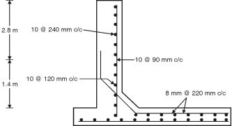
Fig. P. 5.6.4
Ex. 5.6.5: A cylindrical tank of capacity 7,00,000 liters is resting on good unyielding ground. The depth of tank is limited to 5m. A free board of 300 mm may be provided. The wall and the base slab are cast integrally. Design the tank using M20 concrete and Fe 415 grade steel. Draw the following-Plan at base and Cross section through centre of tank.
Soln.:
Step 1: Dimension of tank
H = 5 – 0.3 = 4.7 and volume V = 700 m3
A = 700/4.7 = 148.94 m2
D = √(4 148.94/) = 13.77 ≫14 m
Step 2: Analysis for hoop tension and bending moment
One meter width of the wall is considered and the thickness of the
Wall is estimated as t = 30H + 50 = 191 mm.
The thickness of wall is assumed as 200 mm.
Referring to table 9 of IS3370 (part IV), the maximum coefficient for
Hoop tension = 0.575
Analysis for hoop tension and bending moment (Contd.)
Tmax = 0.575 10 4.7 7 = 189.175 kN
Referring to table 10 of IS3370 (part IV), the maximum coefficient for
bending moment = – 0.0146 (produces tension on water side)
Mmax = 0.0146 10 4.73 = 15.15 kN-m
Step 3 : Design of section:
For M20 concrete σcbc = 7,
For Fe415 steel σst = 150 MPa and m=13.33 for M20 concrete and Fe415 steel
The design constants are:
k = = 0.39
j = 1-(k/3)=0.87
Q = ½ σcbc x j x k = 1.19
Effective depth is calculated as
d = = = 112.94 mm
Let over all thickness be 200 mm with effective cover 33 mm dprovided=167 mm
Ast = = = 695.16 mm2
Spacing of 16 mm diameter bar = = 289.23 mmc/c
(Max spacing 3d=501mm)
Provide #16@275 c/c as vertical reinforcement on water face
Hoop steel :
Ast1 = = = 1261 mm2
Spacing of 12 mm diameter bar = = 89 mmc/c
Provide #12@80 c/c as hoop reinforcement on water face
Actual area of steel provided
Ast = 1412.5 mm2
Step 4: Check for tensile stress:
c =
= = 0.87 N/mm2
Permissible stress = 0.27√fck=1.2 N/mm2 > c Safe
Step 5: Distribution Steel:
Minimum area of steel is 0.24% of concrete area
Ast = (0.24/100) 1000 200 = 480 mm2
Spacing of 8 mm diameter bar = = 104.7 mmc/c
Provide #8 @ 100 c/c as vertical and horizontal distribution on the outer face.
The thickness of base slab shall be 150 mm. The base slab rests on firm ground, hence only minimum reinforcement is provided.
Ast = (0.24/100) 1000 150 = 360 mm2
Reinforcement for each face = 180 mm2
Spacing of 8 mm diameter bar = = 279 mmc/c
Provide #8 @ 250 c/c as vertical and horizontal distribution on the outer face.
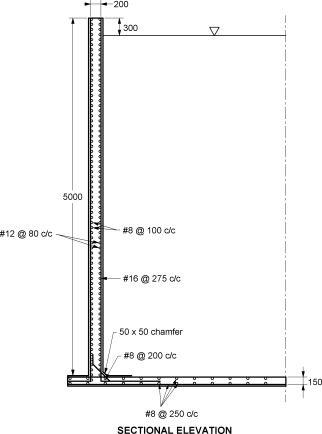
Fig. P. 5.6.5
Ex. 5.6.6: Design a circular water tank to hold 5,50,000 litres of water. Assume rigid joints between the wall and base slab. Adopt M20 concrete and Fe 415 steel. Sketch details of reinforcements.
Soln.:
Step 1: Dimension of tank
Volume of tank V = 550 m3
Assume H = 4.5
A = 550/4.5 = 122.22 m2
D= √(4 x 122.22/) = 12.47 ≫12.5 m
Step 2: Analysis for hoop tension and bending moment
One meter width of the wall is considered and the thickness of the wall is estimated as t = 30H + 50 = 185 mm. The thickness of wall is assumed as 200 mm.
= 8.1 8
Referring to table 9 of IS3370 (part IV), the maximum coefficient for hoop tension = 0.575
Tmax = 0.575 10 4.5 6.25 =161.72 kN
Referring to table 10 of IS3370 (part IV), the maximum coefficient for bending moment = – 0.0146 (produces tension on water side)
Mmax = 0.0146 10 4.53 = 13.3 kN-m
Step 3: Design of section:
For M20 concrete scbc = 7, For Fe415 steel sst = 150 MPa and
m = 13.33 for M20 concrete and Fe415 steel
The design constants are:
k = = 0.39
j = 1 – (k/3) = 0.87
Q = ½ scbcjk = 1.19
Effective depth is calculated as
d = = = 105.7 mm
Let over all thickness be 200 mm with effective cover 33 mm
dprovided =167 mm
Ast = = = 610.27 mm2
Spacing of 16 mm diameter bar = = 329.36 mmc/c
(Max spacing 3d=501mm)
Provide #16@300 c/c as vertical reinforcement on water face
Hoop steel:
Ast1 = = = 1078.13 mm2
Spacing of 12 mm diameter bar = = 104 mmc/c
Provide #12@100 c/c as hoop reinforcement on water face
Actual area of steel provided
Ast = = 1130 mm2
Step 4: Check for tensile stress:
Permissible stress = 0.27√fck=1.2 N/mm2> c Safe
Step 5: Distribution Steel:
Minimum area of steel is 0.24% of concrete area
Ast = (0.24/100) 1000 200 = 480 mm2
Spacing of 8 mm diameter bar = = 104.7 mmc/c
Provide #8 @ 100 c/c as vertical and horizontal distribution on the outer face.
Base slab:
The thickness of base slab shall be 150 mm. The base slab rests on firm ground, hence only minimum reinforcement is provided.
Ast = (0.24/100) 1000 150 = 360 mm2
Reinforcement for each face = 180 mm2
Spacing of 8 mm diameter bar = = 279 mmc/c
Provide #8 @ 250 c/c as vertical and horizontal distribution on the outer face.
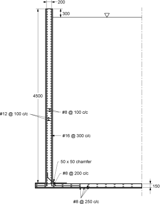
Fig. P. 5.6.6
Ex. 5.6.7: Design a circular water tank with flexible base for capacity of 400000 litres. The depth of water is to be 4 m, including a free board of 200 mm. Use M25 concrete and Fe 415 steel.
Soln.:
Capacity of tank = 400000l = 4000 m3 , Depth of tank = 4 + 0.2 = 4.2 m
Assume diameter of tank = D , D2 4.2 = 4000, D = 34.82 m 35 m
Unit weight of water γ = 9.8 kN/m3
Permissible tensile stress in Fe415 steel = 150 N/mm2
Permissible tensile stress in concrete = 1.3 N/mm2
Maximum hoop tension T = γH
= 9.8 4.2 35/2
= 720.3 kN/m height of base.
s = 150 N/mm2
Area of steel for hoop tension Ash = 720.3 x 1000 / 150
= 4802 mm2
Using 25 mm bars, spacing = (/4) 252 1000 / 4802 =102.22 mm
Provide 25 mm bars @ 100 mm c/c.
Ash provided = 252 1000/100= 4908.74 mm2/m height.
Increase spacing to 200 mm at a height of 1.4 m from base.
Thickness of wall:
Max hoop tension T = 720.3kN
Permissible stress in tension = 1.3 N/mm2
Modular ratio m = = = 11
Equivalent area of concrete /m height = 1000 t + (m – 1) Ash
c =
1.3 = 1300 t + 76576.32 = 720300
1300 t = 643723.6
t = 495.14 mm tprovide = 500 mm
Vertical steel:
ptmin = 0.3%
ptrequired = 0.3 – 0.1 = 0.185 %
Ast (required) = 500 1000 = 928.57 mm2
Use 12 mm bars spacing = 1000 = 121.8 mm
Provide 12 mm bars @ 110 mm c/c.
Base slab:
Ast minimum = 150 1000 = 450mm2
provide half reinforcement.
Near each face
Ast = 225 mm
Use 8 mm bars, s = 82 = 223 mm
Provide 80 mm bars @ 220 mm c/c on both faces in both directions.
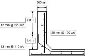
Fig. P. 5.6.7
Ex. 5.6.8: Design a circular water tank with flexible base for capacity of 350000 litres. The depth of water is to be 4 m, including a free board of 500mm. Use M25 concrete and Fe415 steel.
Soln.:
Capacity of tank = 350000 l = 3500 m3, Depth of tank = 4 + 0.5= 4.5 m
Assume diameter of tank = D , D2 4.2 = 3500, D = 32.57 m 33 m
Unit weight of water γ = 9.8 kN/m3
Permissible tensile stress in Fe415 steel = 150 N/mm2
Permissible tensile stress in concrete = 1.3 N/mm2
Maximum hoop tension T = γH
= 9.8 4.5 33/2
= 727.65 kN/m height of base.
s = 150 N/mm2
Area of steel for hoop tension Ash = 727.65 x 1000 / 150
= 4851 mm2
Using 25 mm bars, spacing = (/4) 252 1000 / 4851 = 101.19 mm
Provide 25 mm bars @ 100 mm c/c.
Ash provided = 252 1000/100= 4908.74 mm2/m height.
Increase spacing to 200 mm at a height of 1.5 m from base.
Thickness of wall:
Max hoop tension T = 727.65kN
Permissible stress in tension = 1.3 N/mm2
Modular ratio m = = = 11
Equivalent area of concrete /m height = 1000 t + (m – 1) Ash
c =
1.3 = 1300 t + 76576.32 = 727650
1300 t = 651073.68
t = 500 mm tprovide = 500 mm
Vertical steel:
ptmin = 0.3%
ptrequired = 0.3 – 0.1 = 0.185 %
Ast (required) = 500 1000 = 928.57 mm2
Use 12 mm bars spacing = 1000 = 121.8 mm
Provide 12 mm bars @ 110 mm c/c.
Base slab:
Ast minimum = 150 1000 = 450mm2
provide half reinforcement.
Near each face
Ast = 225 mm
Use 8 mm bars, s = 82 = 223 mm
Provide 80 mm bars @ 220 mm c/c on both faces in both directions.
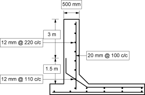
Fig. P. 5.6.8
Ex. 5.6.9: Design a circular water tank resting on ground with flexible base for capacity of 200000 litres. The depth of water is to be 2.5 m, including a free board of 500mm. Use M25 concrete and Fe415 steel.
Ans.:
Capacity of tank = 200000 l = 2000 m3 , Depth of tank = 2.5 + 0.5= 3 m
Assume diameter of tank = D, D2 3 = 2000, D = 29.13 m 30 m
Unit weight of water γ = 9.8 kN/m3
Permissible tensile stress in Fe415 steel = 150 N/mm2
Permissible tensile stress in concrete = 1.3 N/mm2
Maximum hoop tension T = γH
= 9.8 3 30/2
= 441 kN/m height of base.
s = 150 N/mm2
Area of steel for hoop tension Ash = 441 x 1000 / 150
= 2940 mm2
Using 20 mm bars, spacing = (/4) 202 1000 / 2940 = 106.85 mm
Provide 20 mm bars @ 100 mm c/c.
Ash provided = 202 1000/100 = 3141.59 mm2/m height.
Increase spacing to 200 mm at a height of 1 m from base.
Thickness of wall:
Max hoop tension T = 441kN
Permissible stress in tension = 1.3 N/mm2
Modular ratio m = = = 11
Equivalent area of concrete /m height = 1000 t + (m – 1) Ash
c =
1.3 = 1300 t + 49008.8 = 441000
1300 t = 391991.2
t = 301.5 mm tprovide = 325 mm
Vertical steel:
ptmin = 0.3%
ptrequired = 0.3 – 0.1 = 0.235 %
Ast (required) = 325 1000 = 763.75 mm2
Use 12 mm bars spacing = 1000 = 148.08 mm
Provide 12 mm bars @ 140 mm c/c.
Base slab:
Ast minimum = 150 1000 = 450mm2
provide half reinforcement.
Near each face
Ast = 225 mm
Use 8 mm bars, s = 82 = 223 mm
Provide 8 mm bars @ 220 mm c/c on both faces in both directions.
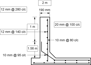
Fig. P. 5.6.9: Reinforcement diagram
Ex. 5.6.10: Design a circular water tank with flexible base for capacity of 300000 litres. The depth of water is to be 4 m, including a free board of 200mm. Use M20 concrete and Fe415 steel.
Soln.:
Capacity of tank = 300000 l = 3000 m3 , Depth of tank = 4 + 0.2= 4.2 m
Assume diameter of tank = D ,
D2 4.2 = 3000, D = 30.15 m 30 m
Unit weight of water γ = 9.8 kN/m3
Permissible tensile stress in Fe415 steel = 150 N/mm2
Permissible tensile stress in concrete = 1.3 N/mm2
Maximum hoop tension T = γH
= 9.8 4.2 30/2
= 617.4 kN/m height of base.
s = 150 N/mm2
Area of steel for hoop tension Ash = 617.4 1000 / 150
= 4116 mm2
Using 25 mm bars, spacing = (/4) 252 1000 / 4116 = 119.25 mm
Provide 25 mm bars @ 110 mm c/c.
Ash provided = 252 1000/110= 4462.49 mm2/m height.
Increase spacing to 220 mm at a height of 1.3 m from base.
Thickness of wall:
Max hoop tension T = 617.4kN
Permissible stress in tension = 1.3 N/mm2
Modular ratio m = = = 11
Equivalent area of concrete /m height = 1000 t + (m – 1) Ash
c =
1.3 = 1300 t + 69614.8 = 617400
1300 t = 547785.16
t = 421.37 mm tprovide = 420 mm
Vertical steel:
ptmin = 0.3%
ptrequired = 0.3 – 0.1 = 0.209 %
Ast (required) = 420 1000 = 877.8 mm2
Use 12 mm bars spacing = 1000 = 128.8 mm
Provide 12 mm bars @ 110 mm c/c.
Base slab:
Ast minimum = 150 1000 = 450 mm2
Provide half reinforcement.
Near each face
Ast = 225 mm
Use 8 mm bars, s = 82 = 223 mm
Provide 80 mm bars @ 220 mm c/c on both faces in both directions.
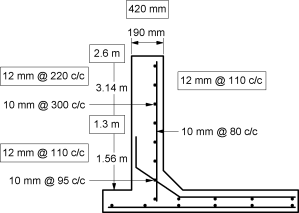
Fig. P. 5.6.10: Reinforcement diagram
5.7.1 Preliminary Dimensions of Water Tank:
The exact analysis of rectangular water tank is difficult and the design cab be done by approximate method as per is IS3370. Two cases are considered for rectangular water tank.
1. When < 2 :
In this case the tank walls are assumed to cantilever continuous frame subjected to hydrostatic pressure. The bottom or 1 m (which is greater) is designed as cantilever and the top portion of a continuous frame in which moments are calculated by moment distribution. In addition to the walls are subjected to direct tension due to hydrostatic pressure.
The direct tension in long wall:
Specific weight of water = w (H h) × B
The direct tension in short wall = × L
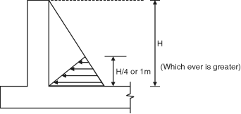
Fig. 5.7.1
2. If > 2:
The longer wall are considered as vertical cantilever for the whole height from the base the short wall is to be designed as simply supported over long wall. The maximum BM in long wall at the base.
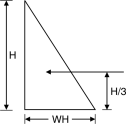 P = × wH × H
BM= × wH × H × =
The maximum BM at the junction
Of steel and long wall = B2
Fig. 5.7.2
Maximum positive BM at the centre of short wall =
The maximum BM for the bottom of short wall = or
Direct tension in long wall = direct tension in short wall
=
Analysis of tank wall subjected to bending moment and pull.
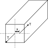 5.7.2 Analysis and Design of Tank Wall Subjected to Bending Moment and
Pull :

Fig. 5.7.3
Let tank wall subjected to BM ‘M’ and axial pull T, resultant moment is
Resultant BM = M – T X
X – distance of steel at center
Ast1 =
Providing the tank of size = L = 4.4 m B = 3.5 m
L = 1.25 B = 1.25 3.5 = 4.37 = 4.4 m
Area = L B = 4.4 3.5 = 15.40 > 14.06 ...OK
Design of bottom height:
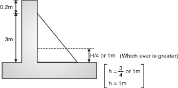
Fig. 5.7.4
The bottom portion of height
h = or 1 m (which is greater)
Is designed as cantilever and the portion above it shall be designed as continuous frame.
Intensity of water pressure at base = W H = 10 3 = 30 kN/m2
1 m3 = 1000 liters
1 kl = 1000 liter
1 m3 = 1 kl
Steel for pull
Ast2 =
Total area of steel, As = Ast1 + Ast2
Ex. 5.7.1: A rectangular water tank open at the top is to be provided at the ground level to accommodate 45 kl of water. The depth of water is to be about 3 m with FB of 0.2. The ratio of length of longer to shorter side of tank is limited to 1.25. Design the tank assuming M20 and Fe250.
Soln.:
Given:
Capacity = 45 kl
1 kl = 1 m3 = 45 m3
Depth of water = 3m
Free board = 0.2 m
Height of tank = 3 + 0.2 = 3.2 m
 Volume = L B H
45 = L B 3.2
L B = 14.06
= 1.25 B
L = 1.25 B
1.25 B B = 14.06
B = 3.35 m 3.5 m Fig. P. 5.7.1
Intensity of pressure at 1 m from base
= w H = 10 2 = 20 kN/m2
For 1 m depth of wall= 10 1 = 10 kN/m2

Fig . P. 4.7.1(A)
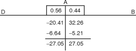
Moment distribution:
Joint | Member | K | k | D. F. = |
A | AB | I/4.4 | + | 0.44 |
| AD | I/3.5 |
| 0.56 |
|
|
|
|
|
= = = 32.26kN/m w-at 1 m from base
= – = = – 20.41
Maximum simply supported BM for longer span
= = = 48.4 kN.m
Net BM = 48.4 – 27.06
At centre = 21.34 kN.m
For shorter span:
Maximum S. S. BM = = = 30.625 kN.m
Net BM at centre = 30.625 – 27.06 = 3.57 kN.m
The pull in longer wall =
TL = = = 35 Kn


Fig. P. 5.7.1(B)
Pull in short wall = = = 44 kN
Thickness of wall:
1. Minimum thickness = 100 mm
2. (30 mm per meter depth of water) + 50 = (30 3) + 50 = 140 mm
3. 60 mm per meter length of water = 60 4.4 = 264 mm
Take greater value = 264 mm
Assume t = 300 mm
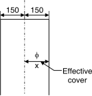
Design of wall to direct tension and moment:
x = Eccentricity of T
x = 150 – Efficiency cover
= 150 – 40 = 110 mm = 0.11 m
Efficiency cover = Clear cover + = 30 + = 40 mm
For longer wall
Net BM = M – TL x Fig. P. 5.7.1(C)
(at mid span) = 21.35 – 35 0.11 = 17.50 kN.m
And at junction = M – TL x = 27.06 – 35 0.11 = 23.2 kN.m
For shorter wall
Net BM = m – TB x (mid span) = 3.57 – 44 0.11 = – 1.27 kN.m
Negative sign indicate tension on water face
At junction = M – TB x = 27.06 – 44 0.11 = 22.22 kN.m
Check for depth:
M = f Z
f = cbt for M20 cbt = 1.7 N/mm2
Z =
b = 1000 mm = 1 m
Mr = D = t = ?
Equating maximum BM to Mr
Maximum BM = 23.2 106 N.mm
23.2 106 =
D = 286 < 300 mm …OK
Assuming D = 300 mm
d = 300 – 30 – = 260 mm
Area of steel at junction:
1. Ast in shorter wall at junction
Ast = + = + = 1236.9 mm2
For Fe 250 st = 115 N/mm2
M20 and Fe 255
J = 0.87
Ast(read) in long wall at junction
Ast = + = +
 = 1207.74 mm2 (1211.5)
Ast (min) :
= 0.2 + (450 – 300)
Ast min = 0.24 % of Ag
= 1000 D = 1000 300
= 720 mm2 Fig. P. 5.7.1(D)
Assuming 16 mm bars
Spacing = = 162 = 160 mm c/c
Providing 16 mm bar at the spacing 160 mm c/c horizontally. In the depth from 1 m up to 2 m above the base at the junction in the long and short wall for a distance 0.25 l from the support.
Since the water pressure decreasing towards the top area of steel above 2 m from base = = 618 mm2 Ast (min). = 720 mm2.
Assuming 12 mm bar
Spacing = 150 mm c/c
Providing 12 mm bar @ 150 mm c/c in the top 1.2 m height of the wall.
Ast in centre of span:
1. In shorter wall:
Ast = +
= + = 431.62 < Ast (min)
Provide Ast = 720 mm2
Providing 12 mm bars
Spacing = = 150 mm c/c
Providing 12 mm bars @ 150 mm c/c
2. Longer wall:
Ast = +
= + = 977.08 < Ast (min)
Assuming 16 mm bars
Spacing = 200 mm c/c
Distribution steel:
(Ast)min = 1000 D = 1000 300 = 720 mm2
On each face = = 360 mm2
Assuming 8 mm bar
Spacing = = 130 mm c/c
Design of bottom 1 m height:
Pressure intensity at base = wH = 10 3 = 30 kN/m2
 Cantilever moment at the base
= 30 1 = 5 kN.m
Ast = =
= 192.21 < Ast (min) Fig. P. 5.7.1(E)
Provide Ast = 720 mm2
Steel on each face = = 360 mm2
Providing 10 mm @ 210 mm c/c on both faces.
Base slab:
The water tank is resting on ground providing 150 mm thick slab.
Ast = 0.3 % of Ag = 1000 150 = 450 mm2
On each face = = 225 mm2
Assume 8 mm bars
Spacing = 220 mm c/c
Ex. 5.7.2: Design a rectangular tank resting on ground for a capacity of 80 kl. Use M25 concrete and Fe415 grade steel.
Soln.:
Capacity of tank = 80 kl = 80 m3
Assume < 2
Assume H = 4 m
Area = = 20 m2
Assume L = 1.5 B
1.5B2 = 20
B = 3.65 m
L = 1.5 3.65 = 5.47 m 5.5m
cbc = 8.5 N/m2
M = = 11, st = 115 N/ mm2
Design constants:
n = = = 0.448
j = 1 – = 1 – = 0.850
k = cbc j n = 8.5 0.85 0.448 = 1.619
Horizontal Frame Action:
Critical section is at h = H/4 or 1 m whichever is more.
h = 1m Ph = r(H – h) = 9.8(3 – 1) = 19.6 kN/m2
Fixed end moments are = = = 49.408 kN-m (Long wall)
= = = 21.76 kN-m (Short wall)
Member | Stiffness | Total joint stiffness | Distribution factor |
Short wall | 4E1/3.65 = 1.096 |
| 0.60 |
|
| 1.823 EI |
|
Long wall | 4E1/5.5 = 0.727 |
| 0.40 |
Short wall | 0.60 | 0.40 | Long wall |
| – 21.76 | 49.408 |
|
| – 16.59 | – 11.06 |
|
| – 38.35 | 38.35 |
|
Corner moment = 38.35 kN-m, tension outside
d = = = 153.91 mm
In order to keep section under-reinforced, provide overall thickness of 200 mm with effective cover of 35 mm.
d = 200 – 35 = 165 mm
Direct pull long wall and short wall
TL = Ph = 19.6 = 35.77 kN
TB = Ph = 19.6 = 53.9 kN
Eccentricity of reinforcement from centre of wall
x = – 35 = 65 mm.
Design moment at corner = M – Tx = 38.35 – 35.77 0.065
= 36.02 kN-m
Ast1 = = = 2233.28 mm2
For direct tension, Ast2 = = 311.04 mm2
Total Ast = 2544.32 mm2
Use 20 mm bars s = 1000 = 123.47 mm
Provide 20mm bars @ 120mm c/c
Reinforcement at middle of long walls:
Bending moment = – Moment at corner
= 19.6 – 38.35
= 35.76 kN-m
Design moment = M – TL x
= 35.76 – 35.77 0.065 = 33.43 kN-m
Ast1 = = 2073 mm2
Ast2 = = 311 mm2
Ast = 2073 + 311 = 2384 mm2
Use 20 mm bars
s = = 131.78 mm
Provide these bars on outer face @ 130 mm c/c
Reinforcement for short wall :
M = 38.35 – TB x = 38.35 – 53.9 0.065 = 34.85 kN-m
Ast1 = = 2160.52 mm2
Ast2 = = 468.69 mm2
Ast = 2629.21 mm2
Use 20 mm bars
s = 1000 = 119.48 mm
Provide 20mm bars @ 115 mm c/c
Bending moment at centre of wall
= r (H – h) – Moment at ends
= 9.8(4 – 1) – 38.35 = 10.61 kN-m
Provide minimum reinforcement i.e. 20 mm @ 230 mm c/c
Reinforcement in vertical direction:
Cantilever moment = r = 9.8 4 = 6.53 kN-m
Ast = = = 404.86 mm
Minimum reinforcement = 200 1000 = 600 mm2
Provide 304 mm2 area on each face so that required distribution steel is also available.
Use 10 mm bars, s = 1000 = 258 mm
Provide 10 mm bars @ 250 mm c/c on both faces.
Base slab:
Provide nominal base slab of thickness 150 mm with 8 mm bars @ 220 mm c/c in both directions at top and bottom of slab.
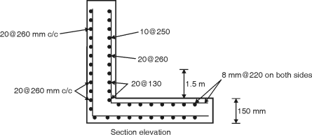
Fig. P. 5.7.2
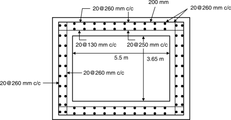
Ex. 5.7.3: Design a rectangular water tank 5m x 4m with depth of storage 3m, resting on ground and whose walls are rigidly joined at vertical and horizontal edges. Assume M20 concrete and Fe415 grade steel. Sketch the details of reinforcement in the tank.
Soln.:
Step 1: Analysis for moment and tensile force
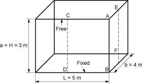
Fig. P. 5.7.3
(i) Long wall:
L/a = 1.67 1.75; at y = 0, x/a = 1, Mx = 0.074; at y = b/2, x/a = ¼, My = 0.052
Max vertical moment = Mx wa3 = – 19.98
Max horizontal moment = My wa3 = 14.04; Tlong = wab/2 = 60 kN
(ii) Short wall:
B/a = 1.33 1.5; at y = 0, x/a =1, Mx = – 0.06; at y = b/2, x/a = ¼, My = – 0.044
Max vertical moment = Mx wa3 = – 16.2
Max horizontal moment = My wa3 = – 11.88; Tshort = waL/2 = 75 kN
Step 2: Design Constants
cbc = 7 MPa, st = 150 MPa, m = 13.33
k = = 0.38
j = 1 – (k/3) = 0.87
Q = 1/2 cbc jk = 1.15
Step 3: Design for Vertical moment
For vertical moment, the maximum bending moment from long and short wall
(Mmax)x = – 19.98 kN-m
d = = = 131.8
Assuming effective cover as 33mm, the thickness of wall is
t = 131.88 + 33 = 164.8 mm 170 mm
dprovided = 170 – 33 = 137 mm
Ast = = = 1117.54 mm2
Step 3: Design for Vertical moment
Spacing of 12 mm diameter bar = = 101.2 mmc/c
(Max spacing 3d = 411 mm) provide #12@ 100 mm c/c.
Distribution steel:
Minimum area of steel is 0.24% of concrete area
Ast = (0.24/100) 1000 170 = 408 mm2
Spacing of 8 mm diameter bar = = 123.19 mmc/c
Provide # 8 @ 120 c/c distribution steel.
Provide #8@ 120 c/c as vertical and horizontal distribution on the outer face.
Step 4: Design for Horizontal moment
Horizontal moments at the corner in long and short wall produce unbalanced moment at the joint. This unbalanced moment has to be distributed to get balanced moment using moment distribution method.
KAC = ; KAC = ; K =
DFAC = = 0.44
DFAB = = 0.56

Fig. P. 5.7.3(A)
Moment distribution table
Joint | A | |
Member | AC | AB |
DF | 0.44 | 0.56 |
FEM | – 14 | 11.88 |
Distribution | 0.9328 | 1.1872 |
Final Moment | – 13.0672 | 13.0672 |
The tension in the wall is computed by considering the section at height H1 form the base.
Where, H1 is greater of (i) H/4, (ii) 1m,
i.e. (i) 3/4 = 0.75, (ii) 1m; H1 = 1m
Depth of water h = H – H1 = 3 – 1 – 2m;
p = wh = 10 2 = 20 kN/m2
Ast1 = = 585.46 mm2
Ast2 = = 333.33 mm2
Ast = Ast1 + Ast2 = 918.79 mm2
Spacing of 12 mm diameter bar = = 123 mmc/c
(Max spacing 3d = 411 mm)
Provide #12@ 120 mm c/c at corners.
Step 5: Base Slab
The slab is resting on firm ground. Hence nominal thickness and reinforcement is provided. The thickness of slab is assumed to be 200 mm and 0.24% reinforcement is provided in the form of #8 @ 200 c/c. At top and bottom
A haunch of 150 x 150 x 150 mm size is provided at all corners
Detailing
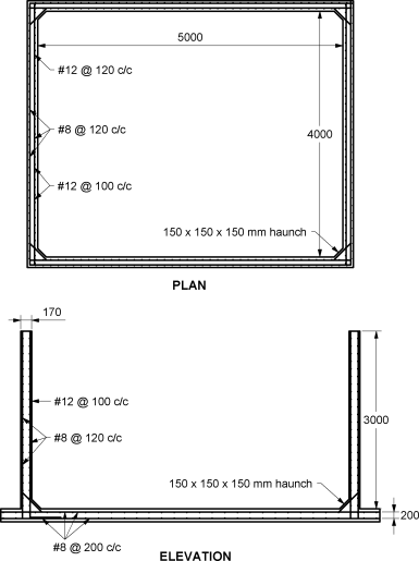
Fig. P. 5.7.3(B)
5.8.1 Geometry of Intze Tanks
(1) Height to diameter ratio = 0.4
(2) Around 10% of total capacity is because of bottom conical portion.
Hence the capacity of vertical container can be equivated with 90%
Of capacity to have H and D.
(3) Diameter of top dome = diameter of container.
(4) Risk of top dome is 0.1 to 0.2 time dia.
(5) Height of conical dome = rise of top dome. It can be equal to
Bottom dome:
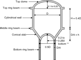
It is approximately 50% m diameter
Compare to diameter of top dome. Rise of
Bottom dame is kept somewhat greater
Approximately 20 to 25% of bottom dome
Diameter.
Volume of tank
(1)Capacity of cylindrical portion = D2H
(2)Capacity of Bottom conical dome
=
Fig. A Typical Intze tank
(3) Capacity of bottom dome = (3r2 + h2) h
(4) Total capacity = (1) + (2) – (3)
Q1. Design an Intze tank for a capacity of 450m3 (450 kilo litre)
Deciding Preliminary dimensions:
Assuming 15% of capacity is of bottom conical dome
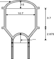 D2H = 85% of capacity
Using = 0.4
D2 (0.4 D) = 0.85 450
D = 10.67 10.7 m
H = 4.25 m
Risc of top dome=1.5 m
Dia of bottom dome=0.5 D
= 0.5 10.7 = 5.35 m
Rise of bottom dome
=0.2 5.35 = 17 1.1 m Fig. Geometry of Intze tank
Height of conical slab
=
= = 2.675 m
Capacity of tank
Capacity of cylindrical portion = D2 H = (10.7)2 4.25 = 382.16
Capacity of bottom conical dome
=
= [(5.35)2 + 5.35 2.675 + (2.675)2] 2.675
= 140.31 m3
Water displace by bottom dome
= (3r2 + h2) h = (3 2.6752 + (1.1)2) 1.1 = 13.06 m3
Capacity of tank=380.02 + 140.31 – 13.06 = 507.21 m3 > 506 m3
Reducing the height to 3.75 m
Total capacity =464.45 m3
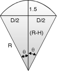
(i) Design of top dome:
Assuming thickness=75 mm
L.L. = 0.75 kN/m2
Self weight = 0.075 25 = 1.875 kN/m2
total load = 2.625 kN/m2
Radius of top dome.
R2 = (5.35)2 + (R – 1.5)2
= (5.35)2 + – 2 R 1.5 + (1.5)2 Fig. Top dome
R = 10.29 m
Tan =
= 31. 32 < 51.51
No hoop tension.
Meridional thrust
T =
T = = 14.56 kN
 Meridional stress = = = 0.194 N/mm2 < 6 N/mm2
Safe (M25 concrete)
Minimum steel
425 – 0.16%
100 – 0.24%
Minimum steel =0.24% = 1000 75
= 180mm2
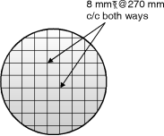
Use 8 mm  bar spacing = = 279 mm Fig. Reinforcement
 Use 8 mm @ 270 c/c both ways
(ii) Design of top ring beam:
Hoop tension in ring beam :
= = 14.56 × 10³ × cos 31.32 ×
= 66.57 kN
 Steel = = = 443.8
444 mm2
Use 4 – nos. – 12 mm  bars e 250 c/c
Assuming one diameter of top ring beam 250 mm
Tensile stress in concrete
at = = Fig. **
m = = = 11.11
cbc = 7.00
m = 13.33 for M20 m = 11.11 for M25 and
at = 0.25 = 1.25 N/mm2
1.25 =
t = 194.72 mm
Use 250 200 of top ring beam with 4 – 12 mm  bars.
bars.
Provide lateral ties of 6mm @ 150 c/c
(iii) Design of cylindrical wall:
Maximum hoop tension
Density of water = = 200.62 kN
Area of steel required = = = 13.37 mm2
Use 16 mm  @ 145 mm c/c
As (provided) = 1386 mm2
Permissible tension stress = 1.25 H mm2, equating with tensile stress in concrete.
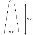 1.25 =
1.25 =
t = 146 mm
Say 200 mm thick at bottom and 100 mm at
Top checking cylindrical wall as a column.
Thrust from top dome T = 14.56 kN
Self weight of ring beam per m = 0.2 5 0.2 25
= 1.2 Fig. Tensile stress
Self weight. Of wall per meter run
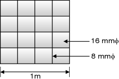 = 3.75 125
= 14.06 kN/m
Total load at the base of wall
=14.56 sin + 1.25 + 14.06
= 22.878 kN/m
Minimum steel = 200 1000 = 430 mm2
 Use 8 mm e 110 c/c
Capacity as a column Fig. Reinforcement
Ac + As s = 1000 200 6 + 9 (8)2 150
= 1267.85 kN/m > 22.87 ok
(iv) Design of middle ring beam:
Assuming 700 × 250 mm middle ring beam self wt of
Beam = 0.7 × 0.25 × 25 = 4.375 kN/m,
Total load on middle ring beam from top
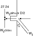
= 22.87 + 4.375 = 27.24 kN/m
W2 = = = 38.53 kN/m
Horizontal component=38.53 sin = 27.24
Hoop tension in beam=27.24 × = 145.76
Ast = = 971.73 mm2
Use 9 nos. 12 mm
Use 6 mm rings at 150 mm c/c
Tensile stress in concrete
 at =
at =
=
= 0.559 Hence safe
(v) Design of conical dome:
(a) Assuming thickness of dome = 300 mm
Self weight = 0.3 × 25 = 7.5 kN/m2 Fig. Forces on middle
Ring beam
Pressure at top of conical dome
 = 3.75 × 10 + 7.5 = 45 kN/m2
Hoop tension = = 240.75 kN
Pressure at base of conical dome
(3.75 + 2.675) × 10 + 7.5 = 71.75 kN/m2
Hoop tension = = 191.93 kN.m
Pressure at midway for conical dome
Fig. Conical dome
Average height > =5.08 m
Average dia = = 8.025 m
Pressure = 5.08 × 10 + 7.5 = 58.3
Hoop tension = = 233.92 %
Maximum hoop tension = 240.75 kN
Ast = = 1605 mm2
 Use 16 mm e 120 c/c
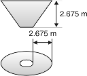 (b) Design of conical dome as slab:
Total load of water on conical dome / m
= average height × 1 × width (plan) × 10
= 5.08 × 1 × 2.675 × 10 = 135.89 kN
Self wt= 7.5 kN/m
Total load = 135.89 + 7.5 = 143.39 kN/m
Total self weight Fig. Conical dome as slab
=7.47
= 28.27 kN
Total load = 135.8 + 28.27 = 164.07 kN
Maximum BM = = 54.86 kN-m
Effective depth = 300 – 40 = 260
Ast req =
M20 Fe415 M25 and Fe415
Q = 1.2 Q = 1.406
j = 0.89 j = 0.87
Ast required = = 1616.86 mm2
Use 16 mm  e 130 mm c/c. Maximum thrust at the base of conical dome
Total load at the base of conical dome
= 27.24 × × 10.7 + (135.89 + 28.35) × × 8.025
= 5054.4 Kn
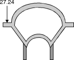
Thrust / m at base of conical dome
=
=
= 425.28 kN/m
Fig. Load at base of conical dome
Maximum stress = =
= 1.41 < 6.0 N/mm safe
Design of bottom dome :
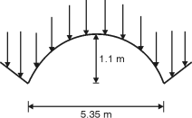
Assuming the bottom dome = 125 mm
Radius of bottom dome
R2 = (R – 1.1)2 +
R2 = R2 – 2.2 R + 1.21 +
Fig. Stress
R = 3.8 m
Self weight g dome W3= (2Rh t) 25
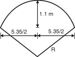 = 2 3.8 1.1 0.125 25
= 82.074
Weight g water above dome,
3.75 + 2.675 =6.425
= 10
= 1313.743 kN Fig. Bottom dome

Total load = 1313.74 + 82.074
= 1395.81 kN
= tan–1
= 44.73 < 51.51
Meridonial thrust
Tsin = W Fig. Load on dome
T =
Meridonial thrust per m
T = =
T = 118 kN
Meridonial stress =T / c/s area
= = 0.94 N/mm2 < 6 N/mm2
Use minimum steel
100 – 0.24 125 – i
425 – 0.16
Pt = 0.234 %
Ast = 1000 125
Ast = 292.3 mm2
Use 8 mm  170 mm c/c both way
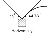 Design of bottom ring beam or circular girder:
T1 = 118
T2 = 425.28
Net thrust acting on ring bear normally
= 425.28 cos 45 – 118 cos 44.73
= 216.8 kN
Assuming size of beam 300 300 mm
Fig. Bottom ring beam
Hoop compression =Tc D/2
= 216.8 = 579.94 kN
Hoop stress = = 6.44 > 6 not safe.
Use size and beam 300 450 mm
Hoop stress = = 4.29 < 6 N/mm2 …ok
 Vertical load per ‘m’ ring beam
w = 425.28 sin 45 + 118 sin 44.73
= 383.76 kN/m
Assuming 6 column support each beam
Length of each segment= = 2.8 m Fig. Beam ring
Total load on beam
= 383.76 2.8 + 0.3 0.45 25 2.8
= 1083.97 kN
Coefficients for B.M. And torsion
Number of supports | | K1 or C1 | K2 or C2 | K3 or C3 | Value g for torsion moment |
4 | 90 | 0.137 | 0.021 | 0.021 | 19.25 |
5 | 72 | 0.108 | 0.054 | 0.014 | 15.1 |
6 | 60 | 0.089 | 0.045 | 0.009 | 12.75 |
7 | 51 | 0.077 | 0.037 | 0.007 | 10.75 |
8 | 45 | 0.066 | 0.030 | 0.005 | 9.5 |
9 | 40 | 0.060 | 0.027 | 0.004 | 8.5 |
10 | 36 | 0.084 | 0.023 | 0.003 | 7.5 |
K1 WR = Maximum negative BM
K2 WR = Maximum positive BM
K3 WR = Maximum torsional BM
R = radius of girder
W = total load on girder
For 6 column supports
Maximum negative BM= K1 WR
= 0.089 1083.97
= 258.06 kN.m
Maximum positive BM=K2WR
= 0.045 1083.97 = 130.4 kN.m
Maximum torsional BM=K3 WR
= 0.009 1083.97 = 26.09 kN-m
Maximum SF = W/2= = 541.9 kN
Equivalent BM = M + MT
MT = T
= 26.09 = 38.36
Equivalent moment at support
= 258.088 + 38.36 = 296.4 kN-m
BM at midspan =130 kN.m
BM maximum =296.4 kN.m
d = M = Qbd2
= = 838.27 mm
Provide d = 900 mm D = 950 mm
Steel required at support
=
= 2524 mm2

 using 8 bars of 20 mm
Steel required at midspan
= = 1107 mm2
 Using 4 bars of 20 mm
Shear R/F
Critical shear =541.9 – 0.9
= 193.5 kN
Shear R/F
As = pitch
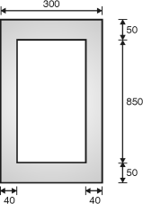
s = 190 N/mm2 Fig. Beam cross section
b1 = 300 – 2 40 = 220
d1 = 950 – 2 50 = 850
P = pitch
 Using 10 mm two legged stirrups
As =/4 (10)2 2 = 157.08 mm2
157.08 = P
P = 129.43 mm say 125 mm
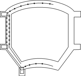
Fig. Reinforcement details
Q. 2 An Intze tank is to be provided for 1000 KJ capacity. Determine the dimensions of all the components of the tank.
Capacity of tank=1000 k J = 1000 103 liters = 1000 m3
cbc = 8.5 N/mm2, st = 150 N/mm2 , m = 11
ct = 1.3 N/mm2, cc = 6 n/mm2, n = 0.384, j = 0.872
K = 1.423
Dimensions of tank:
Let the diameter of cylindrical portion=D
Diameter of bottom ring girder =0.6D
Height of conical shell h3 = 0.2D
Height of bottom spherical dome=
The volume of tank
V = Volume of cylindrical portion + Volume of conical portion
– Volume of bottom spherical dome portion
= D2 h2 + h3 – (3R2 – h4)
D1 = 0.6D, h2 = 0.4D, h3 = 0.2D, h4 =
Radius of bottom dome R2 is
= 0.36 = 0.09D2
R2 = 0.386 D
V = D2 0.4D + (D2 + 0.36D2 + 0.6D2)
–
= 0.374 D3
0.374 D3 = 1000
D = 13.88 m
Let D = 14 m, D1 = 0.6D = 0.6 14 = 8.5 m
h2 = 0.4D = 0.4 14 = 5.5 m
h3 = 0.2D = 2.8 m
h4 = = 2 m
Actual volume of tank
2 (2R2 – 2) = R2 = 5.52 m
V = 142 5.5 + 2.8 (142 + 8.52 + 14 8.5)
– 22 (3 5.52 – 2)
= 1069m3
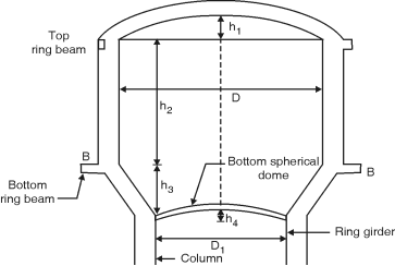
Fig. Dimensions of Intize Tank
Q.3. The inner dimensions of an Intze tank are as shown in figure. Design top dome, top ring beam and side wall. Use M25 concrete and Fe-415 grade steel.
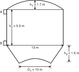
Fig. **
Design of Top dome:
Diameter = 13 m
Let rise = 1/7 13 = 1.86 m
Radius of spherical dome – 2 (2R1 – 2) = 6.52 R1 = 11.56 m
Semi-central angle = cos– 1= 34.21
Let the thickness of dome = 75 mm
Self weight = 0.075 1 1 25 = 1.875 kN/m2
Live load = 1.5 kN/m2
Total = 3.375 kN/m2 4 kN/m2
Meridoinal thrust T1 = w R1 = = 25.31 kN/m
Meridoinal stress = = 0.34 N/mm2 < 6 N/mm2
O.K.
Circumferential force = T2 = wR1
= 4 11.56
= 12.93 kN/m
Circumferential stress = = 0.172 N/mm2 < 6 N/mm2
O.K.
Provide nominal reinforcement of 0.3 % in circumferential and radial direction.
Ast = 75 1000 = 225 mm2
Using 8mm bars, S = 1000 = 223 mm
Provide 8mm bars at 200 mm c/c in radial and circumferential directions.
Design of Top Ring (Beam A–A) :
Hoop tension = T1 cos = 25.31 cos 34.21 = 136.05 kN
Ast = = 907mm2
Provide 5 bars of 16mm diameter
Astprovided = 5 162 = 1005.31 mm2
Area of concrete:
1.3 = =
Ac = 93595.44 mm2
Assume b = 300mm
Provide 300 350 mm top ring beam with 5 bars of 16mm (2 at top and 3at bottom). Also provide nominal shear reinforcement of 6mm bars @ 300mm c/c.
Design of side wall:
Hoop tension at base of tank = 9.8 5.5 = 350.35 kN
Ast = = 2335.67 mm2
Use 16 mm bars on each face
s = 1000 = 172.16 mm
Provide 16 mm bars on each face @ 170 mm c/c
Ast provided = 2 162 = 2680 mm2/m height
Area of concrete :
1.3 = =
Ac = 240020 mm2 /m height
t = = 240.02 mm
Provide t = 250 mm
Distribution steel:
P = 0.3 – 0.1 = 0.25
Area of distribution steel required = 275 1000 = 687.5 mm2
Area of distribution steel required on each face = 687.5/2 = 343.75 mm2. Use 8 mm bars.
S = 1000 = 146 mm
Provide 8 mm bars@ 140 mm c/c on each face.
Hoop tension = 9.8 3.5 = 222.95 kN/m
Ast = = 1486.33 mm2
Ast on each face = 743.17 mm2
Use 12 mm bars
S = 1000 = 152.18 mm
Use 12 mm bars @ 150 mm c/c on each face.