Unit -2
Geometric Design of Highways
Requirement for an Ideal Alignment
The center line layout or position of a road or highway on the ground surface is known as Road Alignment. There are two types of alignments:
a) Horizontal Alignment: includes the straight path, curves or deviation in horizontal direction.
b) Vertical Alignment: includes vertical curves and gradient on the ground.
Since it is difficult to change the alignment once the road has been constructed, therefore care has to be taken in finalizing the alignment beforehand. A road alignment should fulfill the following criteria:
- It should have the shortest path.
- The alignment must be easy to construct and maintain.
- It should be easy for vehicle operation.
- It should be safe in case of designing horizontal and vertical curves.
Factors controlling Alignment
Factors which govern the highway alignment are, as follows:
- Design speed
- Most important factor
- Decided on the basis of type of road such as NH, SH, MDR etc and topography of region
2. Topography
- Helps in deciding the design speed on different terrains:
a) Plain terrain (cross slope up to 10%) – 100 kmph
b) Rolling terrain (cross slope of 10% to 25%) – 30 kmph
c) Mountainous terrain (cross slope of 25% to 60%) – 50 kmph
3. Traffic factors
- Includes vehicular as well as human characteristics
4. Design hourly volume and capacity
- A reasonable value of traffic volume is use for design of highways as it is uneconomical to design road facilities for peak traffic flows
5. Environmental & other factors
- Includes aesthetics, landscaping, air & noise pollution etc.
Engineering Survey for Highway Location
The following steps are involved in finalizing the Highway alignment & preparing the project:
- Map Study:
- It is the very first step of highway survey.
- In this, we use a topographic map of the area under consideration, which can be availed from the Survey of India. Using the map, we can propose different alternatives of the road alignment.
- The topographic map usually has contour intervals of around 30 m to 40 m.
- We can get the details of the natural as well as man-made land features of the area using this map, and based on this we can then suggest a number of options for the road alignment.
- These alternative route options are further studied in detail in the later steps.
2. Reconnaissance Survey:
- This is done to examine the general character of the area for deciding the most feasible routes for detailed studies.
- Basic surveying instruments are used in the reconnaissance survey.
- Following data is obtained from Reconnaissance Survey:
Valley, pond, lakes and other features that may not be present on the topographical map.
A number of cross drainage structures, High Flood Level (HFL), Natural Ground Level etc.
Values of the gradient, the length of gradients and radius of the circular curve.
Soil type along the routes from field identification tests and observation of the geological features.
Sources of construction materials.
3. Preliminary Survey:
This is carried out to collect all the physical information which is necessary in connection with the proposed highway alignment. This work consists of:
- Primary traverse survey
- Study of topographical features
- Leveling work
- Drainage studies & hydrological data
- Soil survey
- Material survey
- Determination of final centre line
This may be done using:
- Conventional Approach: This includes using conventional survey instruments.
- Modern Rapid Approach: This is done by aerial photography.
4. Final Location & Detailed Survey:
- Final Location: The centre line of the road which is finalized in the preliminary survey is located in the field by establishing the centre line. Major and minor control points are set on the ground and the central pegs are driven.
- Detailed Survey: Temporary Bench Marks (TBMs) are fixed and leveling work is done for vertical alignment, earthwork calculation and drainage details.
Special Requirements for Hilly Areas
Alignment through hilly areas is different from alignment along a flat terrain. To ensure efficient and safe operation of vehicles through a hilly area, special measures need to be followed while aligning the highway. Some of these special considerations are, as follows:
- Stability of Slopes: In hilly areas, the road should be aligned along the side of the hill that is stable. A common problem in hilly areas is that of landslides. Excessive cutting and filling in hilly regions leads to steepening of slopes which in turn affects the slope stability.
- Hillside Drainage Facilities: Adequate drainage should be provided along the road. Roads should be aligned in such a way that the number of cross drainage structures required is least in order to reduce the construction cost.
- Special Geometric Standards: The geometric design norms followed in hilly areas are different from those followed in flat terrain. The alignment chosen should enable the ruling gradient to be attained in minimum road length thereby minimizing steep gradient and hairpin road bends.
- Ineffective Rise & Fall: Stringent efforts should be made to ensure that the rise and fall is least.
Design Controls and Criteria for Geometric Design
In order to obtain optimum efficiency of traffic operations ensuring maximum safety at reasonable cost, we design the alignment of highway. Geometric Design of highway alignment deals with the following elements:
- Cross-section elements
- Sight distance considerations
- Horizontal alignment details
- Vertical alignment details
- Intersection elements
Cross Sectional Elements
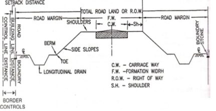
- Friction
- Friction determines the operating speed and distance requirements in stopping & accelerating the vehicles.
- Skidding occurs in a vehicle when transverse movement of tyre > circumferential movement of tyre.
- Slipping occurs when circumferential movement of tyre > transverse movement of tyre.
- Factors affecting friction are:
- Type & condition of pavement surface
- Type & condition of tyre & tyre-pressure
- Speed of vehicles
- Temperature of tyre & pavement
- Coefficient of friction decreases with increase in temperature, load & tyre pressure.
- As per IRC,
- Longitudinal friction coefficient = 0.35 to 0.40
- Lateral friction coefficient = 0.15
- When a longitudinal friction coefficient of 0.40 is allowed for stopping a vehicle, the resultant retardation is 3.93m/s2, which is not too uncomfortable for passengers.
b. Pavement unevenness
- A Bump Integrator is used to measure vertical undulations of pavement surface recorded per unit horizontal length of the road.
- Unevenness index < 150 cm/km for good pavement surfaces of high speed highways
- Unevenness index = 250 cm/km is satisfactory for speed up to 100 km/hr
- Unevenness index = 350 cm/km is uncomfortable to passengers even at 50 km/hr
c. Camber/ cross-slope
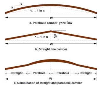
- Camber is the slope provided to the road surface in the transverse direction to drain off the rain water from the road surface.
- The requirement of camber depends upon:
- Type of pavement surface
- Amount of rainfall
- Shape of camber:
- Parabolic & elliptic – preferred by fast moving vehicles, because they require frequent crossing over the crown line during over-taking operations
- Straight line – to provide very flat cross slope in cement concrete pavements
- Note: Superior the road, flatter the camber (RCC > CC > Thick BT > Thin BT > WBM > Gravel > Earth).
Types of Road Surface | Camber | |
Heavy Rainfall | Light Rainfall | |
Cement concrete & high bituminous | 2% | 1.7% |
Thin bituminous | 2.5% | 2% |
WBM & gravel pavement | 3% | 2.5% |
Earth | 4% | 3% |
d. Width of Pavement/ carriageway
Considering that IRC recommends the maximum width of a vehicle to be 2.44m, the minimum width of pavement criteria is given as follows:
- Single Lane = 3.75m
- Two Lane (without kerb) = 7.0m
- Two Lane (with kerb) = 7.5m
- Intermediate Lane = 5.5m
- Multi-lane pavement = 3.5m/lane
- Width of single lane for village roads = 3m
e. Traffic separators/ medians
- As per IRC, minimum desirable width of 5m for medians of rural highways is recommended.
- It may be reduced to 3m where land is restricted.
- Width of median can be further reduced to 1.2 – 1.5m for long bridges.
- IRC Recommendations for Median Width:
- At urban intersection = 1.2m
- For vehicles making right turn = 4m to 7.5m
- For vehicles crossing at grade = 9m to 12m
f. Kerb height
- A Kerb is the edging of a pavement (or a sidewalk) near a road. It indicates the boundary between the pavement and shoulder, or sometimes islands or footpath. The heights of different types of kerbs are:
Low-mountable = 10 cm
Semi-barrier = 15 cm
Barrier = 20 cm
Sight Distance
Sight Distance is the length of road visible ahead to the driver at any point of time. There are 3 major types of Sight Distances considered by IRC, as discussed below:
a) Stopping Sight Distance (SSD)
- Also known as non-passing sight distance
- Depends upon the following factors:
- Features of the road
- Height of the driver’s eye above the road
- Height of the object above the road
- Total reaction time of the driver
- Speed of vehicle
- Efficiency of brakes
- Friction
- Gradient of the road, if any
- As per IRC,
- Height of eye level of driver above the road = 1.2m
- Height of object above road = 0.15m
- As per PIEV Theory, Total Reaction Time varies from 0.5 sec for simple situations to 4 sec in complex situations. It consists of:
- Perception Time: time required by the driver to realize that brakes must be applied
- Intellection Time: time required to understand the situation, based on skill and type of problem
- Emotional Time: time elapsed during emotional sensation
- Volition Time: time taken for final action
- SSD is the sum of the following distances:
- Lag Distance - distance travelled by vehicle during total reaction time
Lag distance = v.t (v is speed of vehicle in m/sec)
= 0.278V.t (V is speed of vehicle in km/hr)
Where, t = total reaction time (sec) = 2.5 sec as per IRC
- Braking Distance - distance travelled by vehicle after application of brakes
Brake distance =  (v is speed of vehicle in m/sec)
=  (V is speed of vehicle in km/hr)
Where, f = longitudinal friction coefficient (0.35 to 0.40)
g = acceleration due to gravity (9.81 m/s)
- Mathematically,
SSD = lag distance + brake distance
SSD = v.t +  (in meters)
SSD = 0.278V.t +  (in meters)
- Effect of Gradient:
SSD = v.t +  (in meters)
SSD = 0.278V.t +  (in meters)
Where, 𝜂 = braking efficiency
n = % gradient
Use + sign for ascending gradient.
Use – sign for descending gradient.
Where, f = longitudinal friction coefficient (0.35 to 0.40)
g = acceleration due to gravity (9.81 m/s)
- For 2-way single lane, minimum SSD = 2 x SSD
b) Safe Overtaking Sight Distance (OSD)
- Also known as safe passing sight distance
- Depends upon the following factors:
- Speed of overtaking, overtaken & the vehicle coming from the opposite direction
- Spacing between overtaking and overtaken vehicle
- Skill and reaction time of driver
- Rate of acceleration of overtaking vehicle
- Gradient of road, if any
- Let,
- d1 = distance travelled by overtaking vehicle ‘A’ during reaction time ‘t’ sec
- d2 = distance travelled by overtaking vehicle ‘A’ during overtaking operation in ‘T’ sec
- d3 = distance travelled by vehicle ‘C’ from opposite direction during overtaking operation in ‘T’ sec at speed ‘v’ m/s
- vb = speed of slow moving vehicle ‘B’
- S = minimum spacing between vehicles ‘A’ and ‘B’ when moving at a speed of vb
Now, S = 0.7vb + 6 (vb is in m/s)
= 0.2vb + 6 (vb is in km/hr)
Mathematically, OSD = d1 + d2 + d3 where,
- d1 = vb.t
- d2 = vb.T + 2S
Here, 2S =  a
a
Therefore, T =  where, a = acceleration (m/s2)
Similarly, T =  where, A = acceleration (kmph/s)
- d3 = v.T
- Hence, OSD = vb.t + vb.T + 2S + v.T (when vb and v are in m/s)
- Similarly, OSD = 0.278Vb.t + 0.278Vb.T + 2S + 0.278V.T (when Vb and V are in km/hr)
- Also,
Vb = V – 16 (kmph)
vb = v – 4.5 (m/s)
c) Safe Sight Distance for entering into uncontrolled intersections (USD)
On all approaches of intersecting roads, there is a clear view across the corners from a sufficient distance so as to avoid collision of vehicles. The area of unobstructed sight formed by the lines of vision is called the sight triangle.
The design of sight distance at intersections may be based on three possible conditions:
- Enabling the approaching vehicle to change speed: The sight distance should be sufficient to enable either one or both of the approaching vehicles to change speed to avoid collision.
- Enabling approaching vehicle to stop: The sight distance should be sufficient to enable either one or both of the approaching vehicles to stop to avoid collision.
- Enabling stopped vehicle to cross a main road: This case is applicable when the vehicle entering the intersection from the minor road are controlled by stop sign and so these vehicles have to stop & then proceed to cross the main road, before another vehicle travelling at its design speed on the main road reaches the intersection.
In addition to the above mentioned, IRC also describes the following two types of sight distances:
d) Intermediate Sight Distance (ISD)
- When overtaking sight distance cannot be provided, intermediate sight distance is provided to give limited overtaking opportunities to fast vehicles.
- ISD = 2 x SSD
e) Headlight Sight Distance (HSD)
- It is the distance ahead of the vehicle, visible to the driver during night time under headlights.
- It is important for upward gradients and ascending stretch of valley curves.
Overtaking Zones with IRC Recommendations
As per IRC Recommendations:
- Desirable length of overtaking zone = 5 x OSD
- Minimum length of overtaking zone = 3 x OSD
Attainment of Super Elevation & Radius of Curves
Super Elevation is the transverse slope to counteract the centrifugal force and to reduce the tendency of the vehicle to overturn or skid.
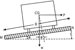
e =  = tan
= tan
Since is extremely small,
Tan ≈ sin = 
Where, B = pavement width
And E = relative elevation of outer edge
Calculation of Super Elevation
The following forces act on vehicle while moving on a circular curve of radius R with speed V m/sec:
a) Centrifugal force P acts horizontally outwards through C.G
b) Weight of the vehicle W acts vertically downwards through C.G
c) Frictional force acts inwards towards the center of the curve
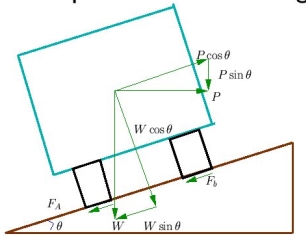
For equilibrium,
P cos = W sin + f (W cos + P sin )
P (cos - f sin ) = W sin + f.W cos
 =
=  = e + f
Also,
e + f =  =
=  (v is speed of vehicle in m/sec)
We can also say, e + f =  =
=  (V is speed of vehicle in kmph)
R = radius of curve in metre
e = rate of super elevation = tan
f = design value of lateral friction = 0.15
Minimum & Maximum Value of Super Elevation (IRC Recommendations)
Maximum Value of Super Elevation
- emax = 7% for plain & rolling terrain
- emax = 10% for hilly terrain without snow
- emax = 4% for urban roads with frequent inter-sections
Minimum Value of Super Elevation
- emin = camber from drainage consideration
Attainment of Super Elevation
Complete super elevation is attained at the end of transition curve or at the beginning of the circular curve. The attainment of super elevation can be split into two parts:
a) Elimination of the crown of the cambered section
b) Rotation of the pavement to attain full super-elevation
There are two methods of rotation of pavement after eliminating camber:
- Rotation about centre line
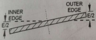
- Depressing inner edge by E/2 and outer edge by E/2.
- The advantage of this method is that the earthwork is balanced.
- The disadvantage of this method is the drainage problem due to depression of the inner edge.
2. Rotation about inner edge
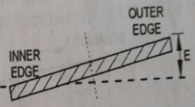
- Outer edge of the pavement is raised by E.
- The advantage of this method is that it can be used in areas of high rainfall and level terrain to avoid drainage problem.
Ruling Minimum Radius of Horizontal Curve
Minimum radius of horizontal curve is given by the following equation:
Rmin = 
Where, V = minimum or ruling design speed in kmph
e = Rate of super-elevation
f = Design value of lateral friction
Ruling Minimum Radius
a) For NH & SH = 360m
b) For MDR = 230m
c) For ODR = 155m
d) For VR = 90m
Horizontal Curves
A horizontal curve acts as a transition between two tangent strips of roadway, allowing a vehicle to negotiate a turn at a gradual rate rather than a sharp cut.
- The design of the horizontal curve is dependent on the design speed for the roadway, as well as the drainage conditions and friction factor for the road.
- The centrifugal force developed at the curve is counter-acted by the transverse frictional resistance developed between the tyres and the pavement.
- Mathematically, centrifugal force P =

- Ratio of centrifugal force P to the weight of the vehicle W is known as centrifugal ratio or impact factor.
 =
= 
- The centrifugal force acting on a vehicle while negotiating a horizontal curve has two effects:
- Overturning Effect (tendency to overturn the vehicle outwards about the outer wheels)
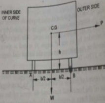
P.h = W x 
For no over-turning condition,
[ =
=  ] ≤
] ≤ 
2. Transverse Skidding Effect (tendency to skid the vehicle laterally outwards)
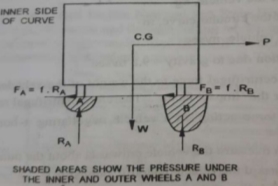
Frictional force = Fw
Centrifugal force = P = 
For no skidding condition, centrifugal force ≤ frictional force
[ =
=  ] ≤ f
] ≤ f
Extra Widening on Horizontal Curves
When a vehicle takes a turn to negotiate a horizontal curve, the rear wheels do not follow the same path as that of the front wheels. Normally the rear wheels follow the inner path on the curve as compared with front wheels. The vehicle has occupies more width that it occupies on straight portion of the road. To compensate this, the carriageway width increased on the entire curved portion of the road, which is called extra widening of pavement on curve.
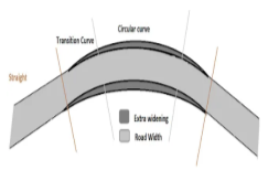
Pavements are provided with an extra-widening when the radius of horizontal curve is less than 300m. Widening is provided for the following reasons:
a) To avoid off-tracking
b) To avoid transverse skidding at speed higher than design speed
c) To account for rigidity of wheel base
d) To increase visibility at curves
e) To consider psychological tendency while overtaking
Extra-widening of pavement (We) is the sum of:
- Mechanical extra-widening (Wm)
- Psychological extra-widening (Wps)
We = Wm + Wps
Here,
Wm =  and Wps =
We =  +
+ 
n = number of lanes
l = length of wheel base (usually taken as 6m)
R = mean radius of the horizontal curve
V = design speed of vehicle in kmph
Also,  is known as off-tracking
As per IRC,
- If R > 300m, We = 0
- If R < 50m, We is provided at inner edge of the curve only.
- If 50m < R < 300m, We is provided at both edges of the curve, inner and outer.
Psychological widening is more important in pavements with more than one lane.
Horizontal Transition Curves
A Horizontal Transition Curve is a curve provided to change the horizontal alignment gradually from straight to circular such that the centrifugal force changes gradually in order to avoid jerk.
- It is introduced by slowly varying the radius of transition curve between infinity to R or R to infinity.
- It is done keeping in mind the comfort of the driver and security of the passengers.
- It also takes into account the gradual introduction of super elevation and extra widening on the road.
- It is done to improve the aesthetic appearance of the road.
- The ideal shape of the transition curve should be such that the rate of introduction of centrifugal force or rate of introduction of centrifugal acceleration should be consistent.
- Ideally,
Ls 
Ls. R = constant
Where, Ls = length of curve
R = radius of curve
- Some common types of transition curves are:
Spiral or clothoid
Lemniscate
Cubic parabola
Calculation of Length of Transition Curve (Ls in metres)
a) On the basis of rate of change of acceleration
Ls =  (v is speed of vehicle in m/s)
Ls =  (V is speed of vehicle in kmph)
Here, R = radius of circular curve (in metres)
C = allowable rate of change of centrifugal acceleration = 
Also, 0.5 < C < 0.8
b) On the basis of rate of introduction of super elevation
Let outer edge be raised at a rate of 1 in N (Value of N varies from 150 in plains to 60 in hilly terrains to 100 in built-up areas).
Ls = e.N (W + We) – When pavement is rotated about inner edge
Ls =  - When pavement is rotated about the centre line
Here, W = original width of pavement
We = extra width of pavement
e = super elevation provided
c) On the basis of IRC recommendations (empirical formulae)
Ls =  (V is speed of vehicle in kmph) – For plain & rolling terrain
Ls =  (V is speed of vehicle in kmph) – For mountainous & steep slope
Design of Vertical Alignment
Summit Curves
Summit curves are vertical curves which are formed when two gradients meet such that there is no discomfort to passengers. But, the main problem in summit curves is to provide adequate sight distance.
Ideally, circular summit curves are best as the sight distance available throughout the summit curve is constant. However, practically simple parabolic curves are used because of best riding qualities, simplicity of calculation work and uniform rate of change of grade. The equation for parabolic summit curves is as follows:
y =a.x2
Where, a = N/2L
N is the deviation angle and L is the length of the curve.
Minimum radius of parabolic curve summit curve is given by R = L/N
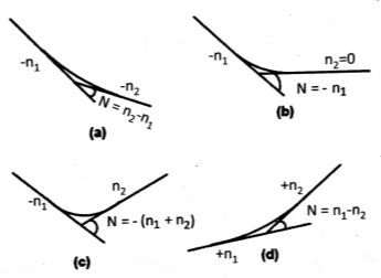
Calculation of Deviation Angle
Length of Summit Curves (L) for Stopping Sight Distance (SSD)
Case 1: L > SSD
L = 
Where, L = Length of Summit Curve (m)
S = SSD (m)
N = deviation angle = algebraic sum of grade
H = height of eye level of driver above road surface = 1.2m
h = height of object above pavement surface = 0.15m
Now, if H = 1.2m and h = 0.15m, then L = 
Case 2: L < SSD
L =  = 2S –
Length of Summit Curves (L) for Overtaking Sight Distance (OSD) and Intermediate Sight Distance (ISD)
Case 1: L > OSD or ISD
L = 
Where, L = Length of Summit Curve (m)
S = OSD/ ISD (m)
N = deviation angle = algebraic sum of grade
H = height of eye level of driver above road surface = 1.2m
Now, if H = 1.2m, then L = 
Case 2: L < OSD or ISD
L =  = 2S –
Crest and Sag/Valley Curves
Crest vertical curves connect inclined sections of a roadway, forming a crest, and they are easy to design. In the design of these curves, it is important to ensure that minimum stopping sight distance (SSD) is available throughout the curve.
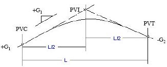
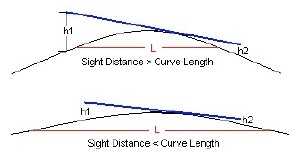
For SSD < L

For SSD > L

Where, SSD = stopping sight distance in meter
Lm= minimum length of vertical curve in meter
A = absolute value of the differences in grades G1 – G2 expressed as a percentage
Sag vertical curves connect descending grades, forming a bowl. The design of sag vertical curves is very similar to the design of crest vertical curves. Four criteria are used to set the minimum length of a sag vertical curve namely, headlight criterion, comfort criterion, drainage criterion, and appearance criterion. These are also known as Valley Curves.
a) Headlight Criterion
The headlight is angled upward at an inclined angle (ß) the headlight intersects the road at D, restricting the available sight distance to S.
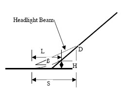
The values for H = 0.6m and ß = 1ᵒ.
A = absolute value of the differences in grades G1 – G2 expressed as a percentage
For S > L

For S < L

b) SSD Criterion
For SSD < L

For SSD > L

Where, SSD = stopping sight distance in meter
Lm= minimum length of vertical curve in meter
A = absolute value of the differences in grades G1 – G2 expressed as a percentage
Gradient and its types & IRC Recommendations
- Ruling Gradient or Design Gradient
- It is the maximum gradient within which the driver attempts to design the vertical profile of the road.
IRC Recommendations | |
1 in 30 (3.3%) |
Plain & Rolling Terrain |
1 in 20 (5%) |
Mountainous Terrain |
1 in 16.7 (6%) |
Steep Terrain |
b. Limiting Gradient or Maximum Gradient
- It is steeper than ruling gradient.
- Used in places where the topography is such that we need to adopt a gradient steeper than the ruling gradient in order to minimize the cost of construction.
c. Exceptional Gradient
- Steeper than the above mentioned gradients and is used only under extreme conditions.
- Should be limited to road stretches ≤ 100m.
- In case of exceptional gradient, the maximum length of ascending gradient that a loaded truck can operate without significant reduction in speed is known as Critical Length of Grade.
IRC Recommendations | |
6.7% |
Plain & Rolling Terrain |
7% |
Mountainous Terrain |
8% | Steep Terrain |
d. Minimum Gradient
It is the minimum gradient required on the road from drainage point of view.
General Requirement of Minimum Gradient | |
1 in 500 |
Concrete drains |
1 in 200 |
Inferior drains |
1 in 100 | Kutcha drains |
Grade Compensation on Horizontal Curve
On sharp horizontal curves, gradient should be decreased to compensate for the loss of tractive effort due to the curve. This reduction in gradient is given by:
Grade compensation, % =  subject to a maximum value of
  where R = radius of curve.
IRC recommends that grade compensation is not necessary for gradients flatter than 4%.
Importance of Highway Drainage
Highway drainage consists of removing or controlling surface and sub-surface water from the road surface and the sub-grade below it.
A part of rain water flows on the ground or road surface, while some part of it percolates into the ground and reaches the ground water table. The sub-grade soil above the ground water table may raise through the soil pores due to capillarity.
Continued presence of water on the road surface weakens the pavement causing pot holes and ruts. Similarly, percolation of water in to the sub-grade reduces its bearing and load dispersion capacity. Loss of sub-grade support leads to failure of the pavement under traffic loads. Hence it is imperative to provide an efficient drainage system along roads and highways.
Sub-surface and Surface Drainage Systems
Surface Drainage System
Under surface drainage, water is collected in longitudinal drains and then disposed of at the nearest water body. Surface water is removed from surface of road by providing camber or cross slope to the road surface. The road surface is also made impervious to prevent the water entering the sub-grade.
In surface drainage we have to take into account the frequency of flood and the use of various drainage structure like culverts and gutters, road side channels, cross slope and side slope, catch drains, longitudinal gradients etc.
- When the road is on embankment, surface water is made to flow down the side slope to the side drains. The side slopes are properly protected by grass so that erosion of side slope does not take place.
- When the road is in cutting, the drains are provided on either side of formation.
- Because of limitation of land, it is necessary to provide underground longitudinal drainage in urban roads.
- Whenever a highway crosses a river or stream, cross drainage works have to be provided.
Sub-surface Drainage System
- The change in water content of the soil affects its bearing capacity. Increase in the value of moisture content reduces the bearing capacity of soil. Thus, there should not be any change in moisture content of the sub-grade of the road.
- The change in water content of the sub-grade may occur due to seepage flow, fluctuations in the ground water table, and percolation of rain water & capillary water.
Control of sub soil flow
- If seepage zone exists within 1 meter depth of the surface then it is required to intercept the seepage flow by introducing deep side drains or sub drains under the pavement. This releases excessive hydrostatic pressure and lowers the water table.
- If the impermeable strata are deep and seepage zone is wide, the drain to keep the water table about 1.3 m below the formation has been found satisfactory. In such a situation it is recommended to take the trench to the impervious strata and intercept the seepage.
Control of high water table
- In order to avoid excessive pressure on the pavement and the sub-grade, it is essential that ground water table should be fairly below the sub-grade.
- For this reason, the water table should be kept at least 1.2 m below the sub-grade level.
- In places where the water table is high, it can be lowered by the construction of longitudinal drainage trenches with drain pipe and filter sand.
Control of capillary rise
- In areas where capillary rise is detrimental to the sub-grade, controlling capillary rise is more effective than lowering the water table.
- This can be done by providing a layer of granular material of suitable thickness between the sub-grade and highest level of water table during construction period of the embankment.
- The thickness of granular material should be such that the capillary water cannot rise above the granular material.
Scope of Arboriculture for Highway
- Growing of trees along roadside is known as arboriculture.
- Trees can be grown on both rural and urban roads.
- Trees should be planted at least 12m away from the centerline of the carriageway in order to maintain clearance at least equal to carriage way width at the level of crown of trees.
- Objectives of Arboriculture:
- To provide attractive landscape of roadside.
- To provide comfort to road users.
- To ensure stabilization of foundation.
- To reduce headlight reflection.
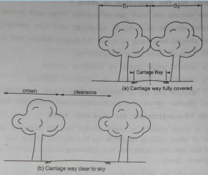
Types of Tree Crowns
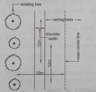
Arrangement of Roadside Crowns
Reference Books:
- S.K. Khanna and C.E.G. Justo - Highway Engineering - 10th Edition, Nem Chand and Bros. Roorkee
- L.R. Kadiyali - Traffic Engineering and Transport Planning - Khanna Publishers