UNIT -4
Airport Engineering
- To most people, air travel is the most sophisticated and enticing form of transportation.
- It is regarded as a status symbol by many individuals because of its speed, continuous journey and relatively exclusive prices.
- International travel between countries separated by seas and oceans are mainly carried out by air transportation.
- It has vastly broadened travel markets by introducing air commerce.
An airport is a facility where passengers connect from ground transportation to air transportation. It is a location where aircrafts take-off and land. The aircraft can also be parked and maintained at the airport. An airport consists of runway for take-offs and landings, terminal buildings and hangars.
Advantages of Air Transportation
- Fastest mode of transport
- Quick, comfortable and efficient service
- Provides easy access to areas which cannot be traversed by road or rail
- Does not have to pass through any physical barriers such as mountains and forests and adopts shortest possible route
Limitations of Air Transportation
- Risky as even a minor accident can cause major loss to life and property
- Costliest mode of transport
- Smaller carrying capacity as compared to ships
- Aerodromes require huge initial and maintenance finances
The schematic diagram of an aero plane with its various component parts are shown in the figure below:
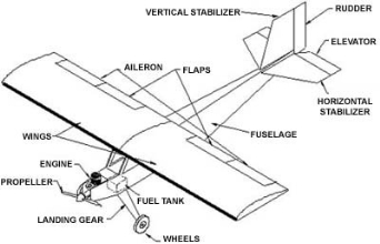
- Engine
- The main purpose of an aircraft engine is to provide a force for propelling the aircraft through the air.
- Aircraft can be classified according to their propulsion as follows:
- Piston Engine
- Turbo Jet
- Turbo fan or Turbo Prop
- Rocket
2. Propeller
- This is provided in the conventional piston engine aircrafts as well as in turbo prop engines.
- When engine & propeller are in front, the machine is described as per tractor types.
- Sometimes, but not very often, the engine & airscrew are behind the wing, this is known as a pusher installation.
3. Fuselage
- It forms the main body of the aircraft & provides for the power plant, fuel, cockpit, passenger, cargo etc.
4. Wings
- The purpose of an aircraft wing is to support the machine in the air when the engine has given it the necessary forward speed.
5. Three Controls
- There are three axes about which an aircraft in space may move.
- The movement of aircraft about the X-axis is called lateral or rolling movement.
- The movements about Y & Z axes are called Pitching and yawing movements respectively.
6. Flaps
- These are somewhat similar to ailerons & are used for increasing the lift on aerofoils.
7. Tricycle Under-Carriage
- It is a structure to support the aircraft while it is in contact with the ground. It has two principal functions
- (i) To absorb landing shocks while aircraft lands.
- (ii) To enable the aircraft to maneuver on ground.
- Runway: It is a defined rectangular area on the land at the airport that is prepared for the landing and take-off actions of an aircraft.
- Runway Shoulder: This denotes the area immediately beyond the edge of the runway and adjacent to the surface provided for drainage, blast protection purposes etc. The shoulder strips are yellow in colour and minimum shoulder width for safe operation is 22m.
- Terminal Building: It is the building component of an airport where passengers can buy tickets, leave or pick-up their luggage and be checked for security reasons. These buildings provide access to the airplanes through gates known as Concourses.
- Apron: It is that area of the airport where aircrafts are parked, loaded & unloaded, re-fueled and boarded.
- Taxiway: This is provided to facilitate the movement between runways and parking areas.
- Aircraft Stand: An aircraft stand/ramp is the enclosed movable connector that extends from the airport terminal gate to the airplane for movement of passengers, cabin crew etc.
- Hangar: A closed structure to hold the aircraft in protective storage for repair and maintenance purposes.
- Control Tower: A tall building or tower at the airport from which instructions are given to the aircraft pilot during take-off and landing operations.
- Parking: Parking facilities offered by an airport are of two types:
a) On-airport Parking: located close to the terminal
b) Off-airport Parking: parking away from the airport complex with a shuttle bus service to the airport
Before planning an airport, the regional map of the area is collected. A regional map provides the following information in detail:
a) Approximate locations of airports in national map
b) Classification of these airports
c) Location of Air Strips
d) Routes of Air Travel
Furthermore, the following data is collected for regional planning:
a) Population data of the area
b) Topography and geographical features
c) Existing airports in the vicinity
d) Air Traffic Characteristics
e) Wind Characteristics
- Type of Propulsion: This includes size of aircraft, its circling radius, speed characteristics, weight carrying capacity, noise nuisance, and performance characteristics.
- Size of Aircraft: This includes the dimensions of the wig span, fuselage length, height of the aircraft, wheel base and tail width.
- Minimum Turning Radius: The turning radius of an aircraft is illustrated when a line is drawn through the axis of the nose gear. The point where this line intersects another line through the axis of the two main gears is known as the centre of the rotation. The distance of the farther wing tip from the centre of rotation represents the minimum turning radius.
- Minimum Circling Radius: Minimum radius with which the aircraft can turn in space. It ranges from 1.6 km for smaller aviation aircrafts to 3.2 km for larger aircrafts and depends upon the type of aircraft, air traffic volume and weather conditions.
- Speed of Aircrafts: If flying speed of the aircraft is 500 kmph and that of headwind is 50 kmph, effective aircraft speed is 450 kmph.
- Aircraft Capacity: It is the number of passengers, baggage, cargo and fuel that can be accommodated in the aircraft.
- Weight of Aircraft & Wheel Configuration: This influences the length of the runway as well as the width & other structural requirements.
- Jet Blast: At very high velocity, the aircraft ejects hot exhaust gases at a speed higher than 300 kmph along with oil spills. This affects the flexible bituminous pavements & hence, cement concrete pavements should be provided at least at these portions.
- Fuel Spillage: At loading aprons and hangars, the areas of bituminous pavements under the fueling inlets, engines etc are kept under constant supervision by the airport authority.
- Noise: Noise generated by aircrafts creates problems in the layout & planning of the airport. FAA Noise Regulations came into effect in 1969.
Selection of Sites
The selection of site for an airport is done considering the factors listed below
- Regional Plan: The site selected should fit well into the regional plan.
- Airport Use: This includes whether the airport is to be used for civilian or for military operations.
- Ground Accessibility: The airport should be easily accessible to all passengers. The roads around the airport should be well constructed & continuous traffic should be ensured.
- Topography: Generally, a raised ground (plateau) is considered to be an ideal spot for an airport.
- Obstructions: The area should be kept free from obstructions as per the zoning laws.
- Visibility: The site should be free from visibility reducing conditions such as fog, smoke & haze etc.
- Wind: The site should be located on the windward side of the city, so that minimum smoke is blown to the site.
- Noise Nuisance: The site should be away from residential areas.
- Soil Type: The most desirable quality of soil for airport construction is the one which contains a reasonable amount of pervious material (such as gravel, sand etc).
- Future Development & Economy: Larger area should be acquired, keeping future developments into consideration. Amongst various alternate sites, the most economical should be prepared.
- Availability of Utilities from Town: Facilities like water supply, sewer, telephones & electricity should be easily available at the airport for smooth running.
Airport Surveys
For site selection of an airport, various types of surveys are carried out:
- Traffic Survey: This is done to determine the amount of present and future air traffic.
- Meteorological Survey: This is done to determine the direction, duration and intensity of wind, rain and barometric pressure.
- Topographical Survey: This is carried out to prepare contour map showing natural features such as rivers, trees etc to ensure proper grading and efficient drainage.
- Soil Survey: This is carried out to determine the type of soil and level of ground water table.
- Drainage Survey: This is carried out to assess the quantity of storm water for drainage. This can be obtained from the rainfall intensity data and the contour maps of the area.
- Material survey: This is carried out to ascertain the availability of the construction material at the site and at a reasonable cost.
Drawings
Drawings/ maps of the surrounding area of the airport land are prepared for the following features:
a) Topography and geographical features
b) Existing airports in the vicinity (types and runway sizes)
c) Air Traffic Characteristics (including flight schedules, flight mapping etc)
d) Wind Characteristics (Wind Rose Diagram, nearby industries for smoke study etc.)
The airport layout should be designed so as to have the following characteristics:
a) Efficient Space Utilization: Wastage of space should be avoided as land prices are quite high.
b) Flexibility: The layout should be designed such that it is flexible enough to adapt to changes.
c) Accessibility: Construction, maintenance & servicing facilities should be easily accessible.
d) Minimum Movement: Minimum movement of men and machines should be ensured.
e) Co-ordination: A good layout ensures co-ordination of all operations.
f) Visibility: This is required to ensure efficient supervision, co-ordination and control over the area.
g) Reduced Discomfort: Proper lighting, drainage of runway and other facilities should be available.
h) Adherence to Statutory Norms: The layout should adhere to the zoning regulations as directed by the authority.
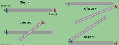
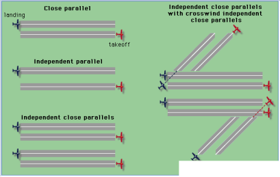
A Runway Configuration is defined as the design or layout of one or more runways, where operations on these runways being used individually or simultaneously at a given time are mutually dependent.
A large airport can have two or more runway configurations at the same time.
1. Single Configuration: an airport consisting of one runway only
2. Parallel Configuration: an airport having two or more runways with parallel centerlines
3. Open-V Configuration: an airport having two intersecting runways whose extended centerlines intersect beyond their respective thresholds
4. Intersecting Configuration: an airport having two or more runways that cross or intersect each other
An airport obstruction is defined as any structure or existing condition at the airport which obstructs the flight of aircraft and its efficient landing or taking off operations at an airport, thereby increasing the risk in these operations.
Obstructions are of 2 types:
a) Imaginary surfaces: assumed surfaces on any airport such that the aircraft moves above that particular surface only
b) Objects with actual heights: different developments in the vertical direction and their height.
The terminal area consists of operational buildings, vehicle parking area, aircraft service hangars etc.
Terminals consist of discrete functional components as interconnected sub-systems:
- Landside Passenger Processors
- Departing passengers: main check-in area, departure concourse
- Arrival passengers: baggage claim, arrival concourse
2. Airside Departure Concourses
- Pre-boarding lounges
- In-transit lounges
3. Checked Baggage Handling Areas
- Outbound flight baggage make-up
- Inbound flight baggage unloading
4. Government Inspection Areas
- Passenger security screening
- Baggage screening
Inter-connectivity between these sub-systems should be ensured using flow charts to depict the movement of passengers, employees, baggage and supplies between these components.
An airport apron is the area where the airport is parked, unloaded or loaded, fuelled and boarded or de-boarded. This area is well-illuminated and is beyond the reach of general public.
Hangars at airports are enclosed buildings in which airplanes are serviced or repaired. Mostly, all airlines have their own hangars to park many aircrafts at the same time. Hangars are usually far away from terminals and runways so as not to interfere with airport traffic.
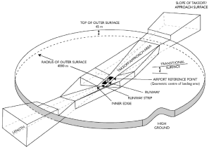
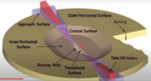
Airport Zones are classified as:
a) Primary Surfaces: aligned longitudinally with each runway and extends 200 ft from each runway end
b) Horizontal Surfaces: horizontal plane 150 ft above the established airport elevation; constructed by swinging arcs around end of the primary surface
c) Conical Surface: slope surface (20:1) extending beyond the horizontal surface
d) Transitional Surface: constructed to join approach & horizontal and approach & transitional surface
e) Approach Surface: longitudinally centered with the runway and extends beyond the primary surface
Objects with actual height:
- Any object within 4.5 km distance from the runway end is considered as an obstruction if its actual height is more than 30m above the ground or above the level of approach end of runway, whichever is higher.
- Any object which is located beyond a distance of 4.5 km from the runway end is considered as an obstruction if its height above 30m increases by more than 7.5m for each additional 1.5 km distance from the runway.
Runway: As per ICAO, a runway is defined as a rectangular area on a land aerodrome prepared for landing and take-off of aircraft. Runways may be natural surfaces of dirt, gravel, grass etc for small aircrafts or choppers or may be man-made surfaces of asphalt, concrete or their mixture for large flights.
Taxiway: A taxiway is a path that connects the runway to other facilities like ramps, hangars, terminals etc and allows navigation of aircrafts to and from the runway. Like a runway, a taxiway can also be made up of natural surfaces of dirt, gravel, grass etc for small aircrafts or choppers or can be made of man-made surfaces of asphalt, concrete or their mixture for large flights. Busy airports usually construct rapid-exit taxiways to allow aircraft to leave the runway at higher speed.
Runway is usually oriented in the direction of prevailing winds.
The head wind, i.e. the direction of wind opposite to the direction of landing & take-off, provides greater lift on the wings of the aircraft when it is taking-off. As such the aircraft rises above the ground much earlier and in a shorter length of runway.
During landing, the head wind provides a braking effect & the aircraft comes to a stop in a smaller length of runway.
Landing & take-off operations, if done along the wind direction, would require longer runway.
- It is not possible to obtain the direction of wind along the direction of the centre line of runway throughout the year.
- On some day of the year or hour of the day, the wind may blow making certain angle with the centre line of runway.
- If the direction of wind is at angle to the runway centre line, its component along the direction of runway will be V*cos and the normal to the runway centre line will be V*sin where V is the velocity of wind.
- The normal component of wind is called cross wind component and may interrupt the safe landing & take-off of the aircrafts.
- The maximum permissible cross wind component depends upon the size of aircraft and the wing configuration.
- Federal Aviation Administration (FAA) recommends that for small aircrafts, the cross wind component should not exceed 15 kmph (10mph) and for mixed traffic it should not exceed 25 kmph (15mph).
- For airports serving the big aircrafts ICAO recommends that the cross wind component should not exceed 35 kmph (23 mph).
- The percentage of time in a year during which the cross wind component remains within the limits as specified above is called win coverage.
- According to FAA, the runway handling mixed air traffic should be so planned that for 95% of time in a year, the permissible cross wind component does not exceed 25 kmph.
- For busy airports, the wind coverage may be increased to as much as 98% to 100%.
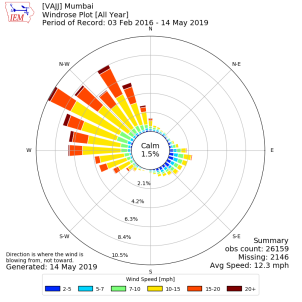
A wind rose is a tool that enables us to graphically visualize the direction and speed of the wind distributed at a particular location. These diagrams help us to understand wind patterns at a site.
In the olden days, wind rose diagrams were used instead of the compass rose, as there was no difference between a cardinal direction and the wind which blew from such a direction. The wind frequency over a period of time is plotted by wind direction, with colored bands depicting wind speed ranges. The direction of the longest spoke depicts the wind direction with the largest frequency.
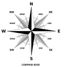
It is the most common way of portraying wind data, and can be measured in terms of ‘speed distribution’ or ‘frequency distribution’. The wind data is collected for a period of 5 to 10 years so as to get the average data with sufficient accuracy.
Wind rose diagrams are of two types:
Type 1: These show direction and duration of wind.
Type 2: These show direction, duration and intensity of wind.
Basic Runway Length is defined as the length of runway considering the following assumed conditions at the airport:
a) The altitude of the airport is at sea level.
b) A standard temperature of 15ᵒC is assumed at the airport.
c) The runway is leveled in the longitudinal direction.
d) There is no wind blowing on the runway.
e) The aircraft is loaded to its full capacity.
f) There is no wind blowing on the way to the aircraft destination.
A minimum runway length of around 1800 m is required for aircrafts weighing lesser than 90000 kg and around 2400 m for larger aircrafts. The various factors that affect the runway length are aircraft performance characteristics, weight of the aircraft, elevation and temperature conditions of the airport, and runway gradient & surface condition.
There are three main corrections to be applied to the basic runway length so as to determine the actual runway length for an airport.
Actual Runway Length = Basic Runway Length + Corrections
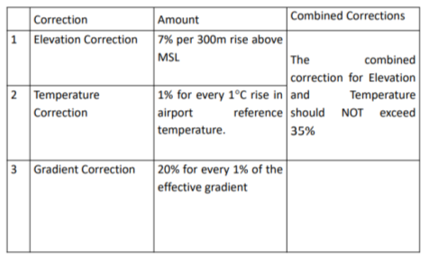
Example: Compute the corrected length of runway for an airport located at an elevation of 150m above MSL if the length of runway under standard conditions is 2000m. The airport reference temperature is 30ᵒC and the effective gradient of the runway is 0.25%.
Solution:
Elevation Correction:  × 2000 ×
  = 70 m
Corrected length = 2000 + 70 = 2070 m
Calculation of standard temperature at elevation of 150m above MSL
= 15°C - 0.0065 × 150 = 14.025 °C
Temperature Correction above Standard Temperature= 32.6° − 14.025° = 18.575 °C
Correction = 2070 ×  × 18.575 = 384.50 m
Corrected Length = 2070 + 384.5 = 2454.50 m
Check for the total correction:  = 22.72% < 35%
Hence, OK.
Gradient Correction:  × 2454.50 × 0.25 = 122.725 m
Corrected Length = 2454.50 + 122.725 = 2577.225 m
On the basis of the function served by a particular airport, they are classified as follows:
- International Airports: Offer customs and immigration facilities for passengers travelling between countries.
- Domestic Airports: Handle only domestic flights i.e., flights within the same country. Domestic airports do not have customs and immigration facilities and so cannot handle flights to or from a foreign airport.
- Custom Airports: Airports for the unloading of imported goods and the loading of export goods.
- Civil Defence Airports: An airport belonging to the armed forces, for the usage of civil aircraft and civil aviation related services.
- Regional Airports: Aircrafts using these airports tend to be smaller business jets or private jets.
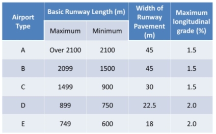
ICAO (International Civil Aviation Organization) classifies airports into various categories in two ways;
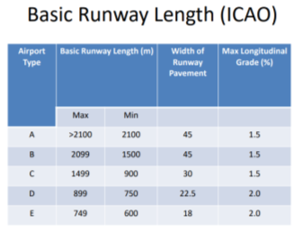
- First Classification is on the basis of the width and length of the runway and its gradient. A type of airport has longest runway length and E type has the shortest length. The classification is given in the table below:
2. Second Classification is on the basis of equivalent single wheel load (ESWL) and the tire pressure of the aircraft. The classification of the airports using numerical 1 to 7 is given in the table below:
Code | Equivalent Single Wheel Load (ESWL) | Tire Pressure | ||
Kg | Lbs | Kg/cm2 | Lbs/in2 | |
1 | 45000 | 100000 | 8.5 | 120 |
2 | 34000 | 75000 | 7.0 | 110 |
3 | 27000 | 60000 | 7.0 | 100 |
4 | 20000 | 45000 | 7.0 | 100 |
5 | 13000 | 30000 | 6.0 | 85 |
6 | 7000 | 15000 | 5.0 | 70 |
7 | 2000 | 5000 | 2.5 | 35 |
Reference Books:
- Ashford, Mumayiz and Wright- Airport Engineering: Planning, Design and Development of 21st Century Airports, 4th Edition
- S.C. Saxena - Airport Engineering (Planning and Design) - CBS Publication