UNIT - 5
Bridge Engineering
A bridge is a structure for carrying the road traffic or other moving loads over a depression or obstruction such as channel, road or railway. It is an arrangement made to cross an obstacle in the form of a low ground or a stream or a river without closing the way beneath.
Bridges can be classified into various types on the basis of following criteria:
- According to Form or Type of Superstructures
- Slab Bridge: It is a bridge of a reinforced-concrete slab resting on abutments and having short span.
- Beam Bridge: It is the simplest & oldest type of bridge consisting of horizontal beams and vertical piers. Beam bridges are long-span bridges while the distance between adjacent piers is small.
- Truss Bridge: It is a load-bearing superstructure composed of elements forming triangular units.
- Arch Bridge: It is a bridge having abutments at each end and is shaped as a curved/ semi-circular arch. The weight of the bridge and its loads are transferred onto the abutments on either side.
- Cable-stayed or Suspended Bridge: This type of bridge has one or more towers, from which cables support the bridge deck, forming a fan-like pattern or a series of parallel lines.
2. According to Material of Construction of Superstructure
- Timber Bridge
- Concrete Bridge
- Stone Bridge
- R.C.C Bridge
- Steel Bridge
- P.C.C Bridge
- Composite Bridge
- Aluminum Bridge
3. According to Inter-span Relationship
- Simply-supported Bridge: The bridge span is supported by an abutment or pier at each end.
- Cantilever Bridge: A cantilever bridge is a horizontal structure supported only on one end.
- Continuous Bridge: It is a truss bridge extending without joints across three or more supports.
4. According to the Position of the Bridge Floor relative to Superstructures
- Through Bridge: It is also known as a half-through arch bridge and is made from steel or reinforced concrete. In this structure, the base of an arch structure is below the deck but the top rises above it. Therefore, the deck slab is within the arch, and the cables and beams suspend the central part of the deck from the arch.
- Suspension Bridge: In this type of bridge, the deck is hung below suspension cables with the help of vertical suspenders.
5. According to Method of Connection of Different Part of Superstructures
- Pinned-connection Bridge
- Riveted-connection Bridge
- Welded-connection Bridge
6. According to Length of Bridge
- Culvert Bridge: These bridges have span less than 6 m.
- Minor Bridge: These bridges have span in the range of 6-60m.
- Major Bridge: These bridges have span greater than 60 m.
- Long-span Bridge: These bridges have span greater than 120 m.
7. According to Function
- Aqueduct Bridge: It is a canal over a river.
- Viaduct: It is a road or railway bridge over a valley or a river.
- Pedestrian Bridge
- Highway Bridge
- Railway Bridge
- Road-cum-Rail or Pipeline Bridge
The bridge structure comprises of the following parts:
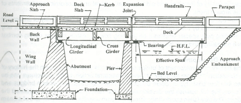
A bridge can be broadly divided into two major parts:
1) Super-structure: The superstructure/ decking of a bridge consist of structural members carrying the route of communication. Therefore, handrails, flooring and guard stones supported by beams, cables, girders, and arches above the level of bearings make up the superstructure.
The superstructure bears the load passing over it and transmits the forces caused by the same to the substructures.
2) Sub-structure: The substructure is the supporting system for the superstructure. This comprises of piers and abutments, wing walls or returns and their foundation.
The other important parts of a bridge are the bearings, approaches and the river training works, like aprons, abutments slopes, etc.
- An ideal site for bridge construction is the one across a valley cut in a sound rock and the river flow does not lead to scouring at bends and other places.
- Factors which govern the stability of bridges are lateral forces, earthquake forces and scouring action of the river.
- Bridges have to be provided across rivers irrespective of the surrounding geology but in highway bridges, there is flexibility in the choice of bridge placement.
- The river bed is usually covered by thick deposits of gravel, sand, and boulders which do not allow stable construction of piers on them. The bridge piers and abutments should always be constructed on sound and stable rock foundation. Depth of sound rock may vary from 5-20 m in some to more than 100 m in others.
- Most igneous and massive sedimentary and metamorphic rocks like gneiss and quartzite are considered strong for bridge foundation. Fractured sandstone, cavernous limestone, clayey cement, slate, schist, shale, peat and organic material act as weak foundation stones for bridge piers.
- Engineering properties like strength values & petrological characters like origin, structure and composition of the rock are obtained by drilling of test bore holes in the rock.
- Preliminary Site Investigation
- The aim of the investigation is to select the most suitable location, and the type of structure satisfying various criteria like optimum cost, road alignment as per demands of traffic safety and aesthetics.
- Poor decisions regarding bridge location and the type of structure can lead to heavy loss of property.
- Step 1: Collection & study of topographical maps and contour plan of the bridge site, indicating the features that would influence the location and design of the bridge and its approaches.
The distances to be covered both on the upstream and downstream side of the bridge site shall be as follows:
a) 100 m for small bridges or when the catchment area is less than 3 km2
b) 300 m for less important bridges or when the catchment area varies from 3 to 15 km2
c) 1500 m for important bridges or when the catchment area is more than 15 km2
- Step 2: Preliminary Survey of the site is carried out to study the alternative bridge sites.
After locating the probable bridge sites on paper either in scale of 1: 50,000 or in 1:2,50,000, these sites are visited to collect certain preliminary data required for thorough examination of the alternative bridge sites from which the final site shall be selected.
- Step 3: Collection of Preliminary Data for Selection of Bridge Sites in order to satisfy the following requirements:
- The channel should be narrow and well defined.
- The river course is stable and has high and stable banks.
- The river should have large average depth in comparison to localized maximum depth so as to ensure uniform flow.
- The bridge site should be far away from the confluence of tributaries especially on the upstream side so that the site remains beyond their disturbing influence.
- The meandering course of the river needs to be studied to locate the nodal points of the river course which are not affected by the meandering.
- The river should have large average depth compared to localized maximum depth to ensure uniform flow.
- The bridge site shall be such that costly river training works are avoided.
- The site shall be sound from geological consideration.
- Materials and labor required for the construction of the bridge shall be easily available at or near the site.
- Step 4: After examination of preliminary data collected for the selection of alternative bridge sites, detailed river survey of the bridge site is carried out.
The discharge ‘Q’ flowing through a river can be found out by the following methods:
a) Empirical Formula
- Ryve’s Formula
Q = CA2/3
Where, Q = maximum flood discharge (m3/s)
C = constant depending upon nature and location of catchment area
A = catchment area (km2)
2. Manning’s Formula
Q = AV where,
Where, Q = maximum flood discharge (m3/s)
A = flow area (m2)
V =  R2/3 S1/2 where,
n = Manning’s constant
R = Hydraulic Radius = A/P (A = flow area, P = wetted perimeter)
S = channel bed slope
3. Rational Method
Q = AI0 where,
Where, Q = maximum flood discharge (m3/s)
A = catchment area (km2)
I0 = Intensity of rainfall in the area (mm/hr)
=  where,
P = constant depending on stream condition
f = factor depending on catchment area
tc = time of concentration (hours) = [ where,
L = distance from critical point to bridge site (km)
H = difference in elevation (m)
b) Direct Methods
- Area Velocity Method
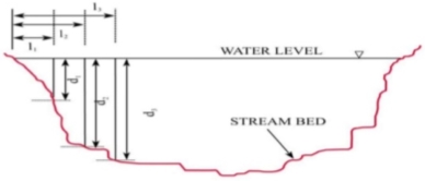
Discharge of the stream is measured by integrating the catchment area and velocity of each point across the stream or river. The stream or river is divided into small sections depending on where velocity and stage height (depth of water) measurements were taken in the cross-section of the stream.
By multiplying the cross-sectional area A [Ai = width of section (wi) stage height (di) where i denotes ith section] by the velocity (Vi), one can calculate the discharge for that section of stream (Qi).
The discharge from each section is then added to determine the total discharge of water from the stream.
2. Dilution Techniques
Two types of dilution techniques are used:
a) Steady Feed Method: A solution of tracer material with concentration C1 is injected at a constant injection rate QT . The tracer disperses laterally in the flow and the tracer concentration distribution occurs from section X1, as shown in the figure below:
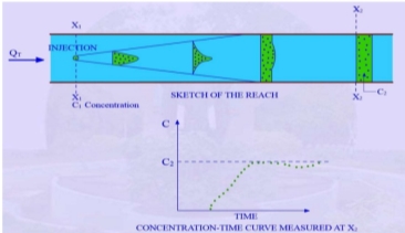
At some section X2, at the downstream end, the tracer is approximately uniformly mixed and the flow is sampled continuously.
By the equation of continuity, QT C1 = (Q + QT) C2
Where, Q = stream discharge
If Q >> QT, the above equation becomes
QT C1 = Q C2
Therefore, Q = 
b) Instantaneous Point Source Method: A quantity of tracer W is injected instantaneously at section X0 and time t0. The cloud of tracer disperses laterally and longitudinally as it moves downstream. The flow is sampled continuously at section X2 where the tracer is completely mixed.

From conservation of mass, W = 
Some common tracers used are salt solutions, radio-active tracers and fluorescent dyes.
3. Ultrasonic Method
An ultrasonic flow meter is a device that measures the velocity of a fluid in a stream using ultrasound technology to calculate volume flow.
Using ultrasonic transducers, the flow meter can measure average velocity of water along the path of an emitted beam of ultrasound, by averaging the difference in the transit time between the pulses of ultrasound propagating into and against the direction of the flow.
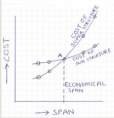
It is defined as that span of the bridge for which the total cost of bridge structure is the least. Economical span depends upon the cost of the sub-structure and the super structure, as can be seen from the graph below.
When a bridge is constructed over a waterway, it causes some contraction in the waterway which results in the rise of water level above the normal level. The rise in water level while flowing under the bridge is known as afflux.
It is the water level in the water body flowing under a bridge due to the highest possible flood ever recorded in the area.
It is defined as the removal of sediments such as gravel and sand around or under the bridge abutments and piers. It is caused by the swift movement of water, resulting in scour holes thereby, compromising the stability of the bridge structure.
Scour depth is important to determine the depth of the foundation.
Clearance is the critical height or minimum vertical distance under a bridge structure that will accommodate the vehicular and rail traffic, based on the design characteristics. Minimum vertical clearance should be 5 meters. Allowance for raising the pavement in the future is also made.
An abutment is a substructure component of the bridge that supports one or both the ends of the bridge superstructure. The abutments also retain the soil in addition to acting as supporting structures. Small bridges are usually supported on two retaining walls at either ends with beams spanning between them. In this case, the retaining walls are known as the abutments.
In large bridges with more than one span, intermediate column-like structures are constructed between the two abutments in order to provide vertical support. These are known as piers.

The following factors affect the design of bridge super structure:
- Clearance requirements: All bridges must be designed to ensure that they are not struck by vehicles which may pass below them. This requirement is met by specifying minimum clearances. In addition, pier position must be such that the impact due to errant vehicles is minimized.
- Type & magnitude of loading: The type & magnitude of loading has a significant bearing on the form of the bridge. Every country has its own specifications for the magnitude of loading on highway and railway bridges.
- Topography & geology site: The overall topography of the site determines the line of the road or the railway. The bridge site is fixed depending upon the topography and terrain of the surrounding area.
- Possible methods of erection: The designer must consider the method by which a bridge will be erected. For example, if a bridge has to be erected consisting of large pieces, the possibility has to be ruled out if adequate access roads are not available.
- Local skills and materials available: The bridge construction should be suited to local technology and easily available material and labor.
- Future inspection and maintenance: Many bridges have deteriorated because of lack of attention to future maintenance at the design stage.
- Aesthetic and environmental aspects: The appearance of bridges has become a matter of importance over the recent years. For example, a bridge with odd number of spans is considered to be more aesthetically pleasing as compared to a bridge with even number of spans.
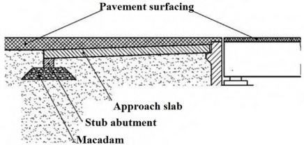
Differential settlement at abutments has been a persistent problem in bridge construction, causing bumps at the end of the bridge, which in turn lead to unpleasant and hazardous driving scenarios.
Thus, in order to minimize or eliminate the differential settlement, the approach slab is constructed with an aim to provide a smooth transition between the roadway pavement and the bridge. It acts as an intermediate bridge to span the portion of embankment directly behind the abutment or back-wall.
Various types of loads act on bridges. The stability of these bridge structures is designed keeping in mind the below mentioned loads.
Brief Specifications of Different Loads, Forces, Stresses on Bridges
- Dead Load: These comprise of gravity loads due to structural elements of the bridge like the deck slab, parapet wall, wearing coat, stiffeners etc. It is the first type of load to be considered in bridge design.
- Live Load: This represents the moving vehicular, pedestrian load on the bridge throughout its length. Live load on the bridge is considered as per IRC specifications which are discussed in the following topic.
- Impact Load: This is due to the sudden load on the bridge pavement caused due to vehicular movement. When the wheel is in movement the live load changes from one wheel to another resulting in the cause of impact loads.
- Wind Load: For short span bridges this can be considered negligible for medium span bridges. Wind load is considered for the design of sub structure only, for long span bridges wind load is considered for design of super structures.
- Longitudinal Forces: These are caused by the sudden braking or accelerating of the vehicle on the bridge pavement. IRC recommends that the longitudinal force = 20% of the live load.
- Centrifugal Forces: For the design of bridges on horizontal curves we need to consider the effect of centrifugal forces on the super structure.

Where, C = Centrifugal Force (kN/m)
W = Live Load (kN)
V = Design Speed (km/h)
R = Radius of the curve (m)
7. Buoyancy Effect: This is to be considered for large bridges that are sub merged under large water bodies.
8. Forces by Water Current: During the construction of a bridge across a river/stream, a part of bridge sub-structure is submerged under water. On this submerged portion, the flowing water induces continuous horizontal forces which are maximum at the top of the water level and zero at the bed level.
9. Thermal Stresses: These are caused due to large variations in temperature leading to crack formation in concrete. In order to resist these stresses expansion joints are provided in the deck slab and additional steel reinforcement perpendicular to main reinforcement is also provided.
10. Seismic Loads: Earthquake loads are to be considered when a bridge is constructed in an earthquake prone area. These induce both vertical & horizontal pressure on the bridge components. The amount of pressure being exerted is directly proportional to the self weight of the structure.
11. Deformation & Horizontal Effects: When the material properties change internally or externally deformation stresses are induced in the structure. Horizontal forces developed due to braking of vehicles, earthquakes & large variations in temperatures.
12. Erection Stresses: These occur in the structures during the construction phase and are resisted by providing suitable member support.
IRC Load Specifications & Requirements of Traffic in the Design of Highway Bridges
IRC 6 Section-II (Loads & Stresses) gives the following live loads specifications and impact factor requirements for the design of highway bridges.
Live Load
Vehicles loading are characterized into four types for road bridges:
a) IRC Class AA Loading: It is generally used for steel bridges and state highways.
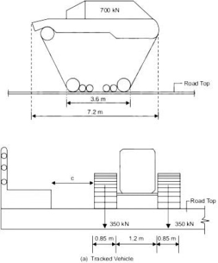
Class AA Tracked Vehicle
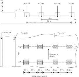
Class AA Tracked Vehicle
b) IRC Class A Loading: This considered for all permanent bridges & culverts. Bridges designed under Class AA loading should always be checked for Class A loading also because greater stresses are attained under Class A loading.
c) IRC Class B Loading: This is adopted for temporary structures like timber bridges.
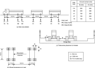
Class A & B Loading
d) IRC Class 70R Loading: This is adopted for permanent multi-lane bridges
Impact Load
To consider impact loads on bridges, an impact factor is used. It depends upon the weight of the vehicle, velocity of the vehicle, bridge span and, many other factors. Impact factor for various types of loading as per IRC is given below.
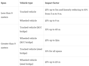
If the span exceeds the above mentioned limits the impact factor is considered using the graph given below.
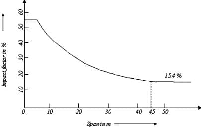
For IRC class A and class B loadings
Impact factor If = A/(B+L)
Where, L = span in meters
A and B are constants
Bridge type | A | B |
RCC | 4.5 | 6.0 |
Steel | 9.0 | 13.50 |
Apart from the super structure impact factor is also considered for substructures
- For bed blocks, If = 0.5
- For substructure up to the depth of 3 meters If = 0.5 to 0
- For substructure greater than 3 m depth If = 0
As discussed above, the sub-structure of a bridge comprises of three main components: Abutments, Piers and Wing Walls. Each of these components is discussed as follows, based on requirement and stability.
Abutments
Bridge abutments connect the deck or surface of the bridge to the ground and help support its weight both horizontally and vertically. In short span bridges, abutments are placed at the either end of the bridge and connected to the embankment, sometimes including a retaining wall. Longer bridges consist of additional abutments placed along the length or span of the bridge to provide necessary support at regular intervals to provide vertical support. The choice of abutments depends upon the available space, geological features of the bridge site and the funds available for bridge construction.
Components of Abutments
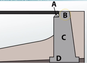
Bridge Seat: It is a horizontal shelf supporting the bridge deck and is near or on the top of an abutment. It is represented by letter A in the above figure.
Wing Walls: They are short retaining walls to prevent erosion and provide stability to bridge structure. These cannot be shown in the figure as they are present on the backside.
Back-walls: These pedestal-like-structures rise above the seat to provide a horizontal brace from the bridge deck and reduce erosion at the connecting point. It is represented by letter B in the above figure.
Pile: An abutment’s pile is either a vertical wall connecting the seat with the foot or a row of columns that are used for the same purpose. It is represented by letter C in the above figure.
Footing: It connects the vertical load-bearing structure of the abutment to the ground and is usually buried beneath the earth. It is represented by letter D in the above figure.
Types of Bridge Abutments
a) Full Retaining Abutments: built at the bottom of the embankment to retain the entire roadway embankment
b) Semi Retaining Abutments: built somewhere between the bottom & top of the roadway embankment
c) Stub/ Sill Abutments: typically short abutments placed on top of the embankment in rocky terrain
d) Gravity Abutments: Resist horizontal loads under their own weight
e) U-Abutments: wing walls of the abutment are placed at right angles to the back wall
f) Spill-through Abutments: soil is allowed to pass through the gaps in the abutments, along the length of the abutments
Design of Bridge Abutments
Step 1: Assumption of Preliminary Dimensions
Step 2: Check for Stability
a) Factor of safety for stability against overturning should be greater than 2
b) Maximum base stress should be less than the safe bearing capacity of the soil
c) Factor of safety for stability against sliding should be greater than 1.5
Step 3: Structural Design of Various Components
Piers
A pier supports the bridge span and transfers vertical and horizontal loads from the superstructure to the foundation. Piers are subjected to large axial loads, moments and shear forces in both transverse as well as longitudinal direction. Since piers are compression elements of a bridge, they are also known as Bents.
Requirements of Bridge Piers
- They must efficiently transfer loads from the superstructure to foundation without causing failure.
- They should be able to withstand all force actions, lateral and longitudinal.
- The material used for construction of piers should be easily available.
- They should be simple to design, cost-effective in terms of construction as well as repair and maintenance and must have a pleasing appearance.
- Bridge piers must be durable against weathering and corrosion.
Types of Bridge Piers
Depending upon the soil conditions, materials used and the construction procedure adopted, bridges can be classified into two types:
a) Solid piers: These are impermeable structure made up of stone masonry (known as Solid Masonry Piers) or mass concrete (Solid RCC Piers).
b) Open piers: These are made up of materials that allow water to pass through them. These are further classified as cylindrical piers, column bents, trestle piers, pile bents and typical framed piers.
Wing Walls
In a bridge, the wing walls are at both ends of the abutments and act as retaining walls for soil supporting the roadway and the embankment. These can be constructed perpendicular to the abutment or can be splayed at different angles. The wing walls are constructed at the same time and of the same materials as the abutments. These walls allow the smooth entry of water into the bridge site and provide support and protect the embankment. They can be constructed purely for aesthetic purposes.
Types of Wing Walls
Based on their position in plan with respect to banks and abutments, the wing walls can be classified as follows:
a) Straight wing walls: These are used for small bridges like railway bridges and on drains with low banks. These consist of weep holes, to allow drainage of soil water.
b) Splayed wing walls: These are used for large bridges across rivers, to ensure smooth entry and exit of water. Usually, they are constructed at an angle of 45°. Weep holes are also provided. Typically, their top width is 0.5 m, face batter is 1 in 12 and back batter is 1 in 6.
c) Return wing walls: These are constructed where banks are high and firm. Typically, their top width is 1.5 m, face is vertical and back batter is 1 in 4. Scouring is a major problem associated with wing walls and abutments both, as the stream water easily erodes the supporting soil.
Design Considerations for Wing Walls
Loading criteria to be considered for the design of wing walls is given as follows:
Earth Pressure due to soil backfill
Surcharge due to live loads
Hydraulic Pressure from saturated soil conditions
The stability of the wing wall is designed so as to resist 'active' earth pressures while the structural elements are designed to resist 'at-rest' earth pressures. This is because the at-rest pressures are developed at the initial stage and the bridge elements are to be designed to accommodate these loads without failure. However, these loads will reduce to active pressure when the wall moves. Thus, stability of the walls is designed to resist this active earth pressure.
Reference Books:
- S Ponnuswamy - Bridge Engineering – Mc Graw Hill
- S.C. Rangwala - Traffic Engineering and Transport Planning - Charotar Publishing House Pvt. Limited, 2009