Unit 1
Introduction To Dams
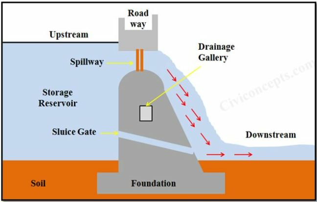
● Dam is a hydraulic structure which is constructed across a river to store water on it’s upstream side.
Or
● Dam is a obstruction constructed across the flow of the river such that a pool of water is stored on the upstream side.
● This pool of water stored on the upstream side is know as “reservoir”
● This stored water is used as and when needed.
● Due to dam construction the water level in upstream side river increased very much.
B. Different terms related to dams:
i. Toe: the downstream portion of the dam where it contacts the bearing surface.
Ii. Heel : the upstream portion of the dam where it contacts the bearing surface.
Iii. Crest: it is the top most surface of the dam may be used as roadways/ pedestrians etc.
Iv. Parapet walls: these are the walls along the length of dam on either sides for the safety purpose.
v. Freeboard: it is the clear vertical distance between the crest and the highest water level.
Vi. Maximum water level: it is the highest elevation to which water can be stored without any overtopping the dam.
Vii. Minimum water level: it is the lowest elevation to which the water in reservoir can be lowered and water still be drawn
Viii. Galleries: these are the openings provided in the structure of dams for the purpose of monitoring work and other maintenance work.

C. Selection of site for a dam:
For a good dam site following requirements are there:
⮚ Foundation:
- Suitable foundation should be available for the different types of dams. As for gravity dams- sound rock, earth dam- foundation of any type with proper treatment
- Foundation should not be built on any fault present in the past.
⮚ Topography :
- Major portion of dams should be on high ground, this would reduce the cost and facilitate drainage.
- To reduce the length of dam, the cross-section of river should be narrow gorge.
⮚ Site for spillway:
- In case of earth and rockfill dam, good site for separate spillway is essential
- In gravity dam, the spillway can be provided at the middle
⮚ Materials:
- Material should be easily available at the site to reduce the transportation cost.
- Material should be of proper strength
⮚ Communication:
- Dam site should be connected to the rail or road link, so, material can be easily transported at the site.
⮚ Locality:
- Local conditions of sites should be healthy and free from mosquitoes, fly breeding etc.
D. Factors governing the selection of type of dam:
There are many physical factors upon which the selection of type of dam is depends;
- Topography
- Materials of construction
- Geology and foundation conditions
- Spillway size and location
- Roadway
- Length and height of dam
- Life of dam
E. Classification of dams:
i. Classification based on use
1a. Storage dam
● Storage dam is constructed to collect water to its upstream side during the period of excess flow in the river in rainy season
● This stored water is then used according to need in different period of water supply.
● Storage dam constructed for purpose such as; irrigation, water power generation, water supply for public health purposes.
● Can be made of stone, concrete, earth and rockfill etc.
b. Diversion dam:
● Diversion dams are constructed to divert the water supply from main stream to branch stream, ditches, canals etc.
● First the water level is slightly increased by the dam and then supply is diverted to the branch distributaries
● eg. Barrage and weir
● mostly used for irrigation, or municipal or industrial uses.
● During floods the excess water is diverted
c. Detention dam:
● It is constructed to store water during floods and release it generally at a safe rate, when the flood receds.
Ii.classification based on hydraulic design:
- Non-overflow dam
● In these dams the top of dam is kept generally at a higher elevation than the maximum HFL.
● These can be made of various materials. Overflow is not allowed in these type of dam, so, any material can be used.
b. Overflow dam:
● These dams are designed to carry the surplus water supply over it’s crest.
● Hence, crest level is kept lower than the maximum HFL.
● The downstream side of dam is made of such material which is not easily susceptible to erosion because of overflow discharge
Iii.Classification based on material:
- Rigid dam:
● Rigid dams are constructed by rigid materials eg. Concrete, steel or timber.
● Classified as;
- Solid masonry
- Arched masonry
- Steel dam
- Concrete buttress dam
- Timber dam
b. Non- rigid dam:
● These are made of flexible material or non rigid materials.
● Classified as;
- Earth dam;
● An earthen dam is made up of soil, which is compacted solidly and resist the forces excerted on it mainly due to shear strength of the soil.
● It is constructed in the areas where foundation can not withstand with the weight of concrete dam
● Hirakud dam – odisha – Mahanadi river
2. Rockfill dam;
● A rockfill dam is build by piling up rock fragments and boulders of large size on the river bed.
● An impervious layer of concrete is placed on the upstream side of the rock fill to make it water tight structure
● Ex. Ramganga dam- uttarakhand – Ramganga river
3. Combined of earth and rockfill dam
Iv.Classification of dam based on structural action:
- Gravity dam:
● A gravity dam is a concrete or masonry dam which resist the forces excerted on it by its own weight.
● It’s cross section is approximately triangular in shape.
● Ex. Bhakra dam- satluj river – himachal Pradesh
b. Arch dam:
● An arch dam is a curved concrete on masonry dam, convex upstream, which resist the forces excerted on it by horizontal arch action.
● It is best suitable at narrow at narrow and extremely high site.
● Ex. Iddukki dam – periar river – kerala
c. Embakement dam
Dams and earthquakes:
● Earthquake forces caused due to sudden sliding of rocks in the earth interior which is due to plate tectonic activity.
● Point of sudden sliding is called as “focus” and it lies with in top 100 Km depth.
● Vertical projection of Focus on the earth surface is called “epicenter”
● Earthquake causes random vibrations in the earth crest, which can be resolved into 3 mutually perpendicular directions.
● This motion causes structure to vibrate.
● These waves impart acceleration to the foundation of the dam and gradually it is transferred to the body of the dam
● For design purpose acceleration can be resolved into 2 components’ i.e. horizontal acceleration (αh) and vertical acceleration αv
● Values of these acceleration are expressed in terms of percentage of acceleration due to gravity.
Effect of vertical acceleration:
αv = Kv.g
Kv = seismic coefficient for vertical acceleration
αv = either increases or decreases the net wt. Of the dam
Vertical acceleration is positive when, acting upward
Negative if acting downward
NOTE: worst condition for design is αv acting downward and thereby reducing net weight of the dam which endangers stability of the dam
Generally force will be opposite to acceleration direction
Effect of horizontal acceleration:
⮚ αh = Kh.g
⮚ where, Kh is the seismic coefficient of horizontal acceleration
⮚ it’s causes two effects;
- Horizontal initial forces:
⮚ horizontal inertial force = w/g * αh
Social issue related to the dam:
⮚ disruption/demolition of human locality
⮚ problems of flood due to overflow in the locality of dam
⮚ waterlogging due to the storage of water
⮚ communicable diseases
⮚ loss of culture etc.
Large dam vs. Small dams:
Large dams:
⮚ Dam with height of 15 m or above from the deepest river depth
⮚ Also in the range of 10 m to 15 m with volume of earth dam exceeds 0.75million m3 and storage exceeds 1 million m3
Small dams:
⮚ Dams not fulfill the above requirements are called as small dam
Dam safety and instrumentation
Objectives:
⮚ The principal objectives of a geotechnical instrumentation plan may be generally grouped into four categories:
- Analytical assessment;
- Prediction of future performance
- Legal evaluation; and
- Development and verification of future designs.
⮚ Instrumentation achieves these objectives by providing quantitative data to assess groundwater pressure, deformation, total stress, temperature, seismic events, leakage, and water levels.
⮚ Total movements as well as relative movements between zones of an embankment and its foundation may also need to be monitored.
⮚ A wide variety of instruments may be utilized in a comprehensive monitoring program to ensure that all critical conditions for a given project are covered sufficiently
Necessity of instrumentation:
1. The casing soils are low in permeability and their performance in sudden draw down condition on u /s side needs to be watched.
2. Due to the pore water pressure present into the body of the dam are in action
3 Dams are located on mostly highly seismic zone hence, vertical settlement of dam and horizontal spread on d/s side is to be monitored
4. Instrumentation is required for the design comparision aspects
5. In case of heavy rainfall locality area of dam, it is necessary to check the saturation level of the d/s of the dam body.
6. To watch performance of horizontal filters proposed in d /s casing zone to reduce pore pressure with the body of dam.
7. The horizontal filter mat of 1.20 m thick has been provided on d/s side. The performance of the same needs to be watched
Types of measurements:
Various types of measurements in dams instrumentation are following;
⮚ pore pressure,
⮚ displacement,
⮚ seepage,
⮚ strains,
⮚ stresses,
⮚ dynamic load,
⮚ uplift pressure,
⮚ Temperature etc.
Instrumentation data system;
⮚ Data collection system;
- Manual readings;
● Data is collected manually and noted down in the field in the reading book, or handled device.
● It is simple to perform and not require higher expertise.
● Data quality can be accessed after collected readings.
b. Standalone data logger
● In this method various data loggers are used for the reading collection at some time interval, or simultaneously at various location
● Frequent event oriented data collection
● Electronic data collection and is consistent
● Instrument is inexpensive and easy to stand/ set up
c. Real time monitoring network;
● Frequent and event driven data collection
● Real time time collection display and notification
● Reduce labor effort in data collection and processing
● Permits for rapid evaluation of monitoring results
Data management and presentation:
● Collection of data in an effective manner suitable for the project and intent
Of the monitoring program
● Validation of data readings and resolution of apparent anomalies;
● Processing and reduction of the data to convert raw readings to useful engineering units; and
● Maintenance of historical data in a usable and easy to evaluate format,
Including suitable backup and archiving procedures.
- Data management
Electronic formats;
⮚ ASCII
⮚ Spreadsheet
⮚ Database
b. Data processing
c. Data maintenance
Instruments:
- Piezometer:
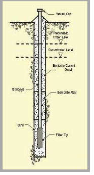
● It is proposed to provide piezometers both in foundation as well as in embankment
Ii. Pneumatic piezometer:
● It consists a porous filter with flexible diaphragm between connected to two tubes.
● The diaphragm is held closed by the external water pressure.
● Tube’s one end is connected to a dry air supply and a pressure gauge.
● Air pressure is applied till it exceeds the external water pressure acting on the diaphragm, which deflects the diaphragm and permits air to vent through the another tube.
● Air supply is stops, and the external water pressure and internal pressure equalize permitting the diaphragm to close.
● The residual internal air pressure is taken as the external water pressure
● Alternatively, the water pressure can be taken as the air pressure required to maintain a constant flow through the tubes.
● Some constant flow types use a third tube connected to a pressure gage to measure pressure at the diaphragm rather than at the inlet to reduce potential errors and eliminate the need for individual calibration curves.
● Advantages;
- Moderately simple transducer, moderately expensive, reliable, fairly long experience record.
- Very short lag time.
- Elevation of readout independent of elevation of tips and piezometric levels.
- No freezing problems.
Iii. Vibrating wire piezometer:
● It consist of a porous stone connected to a sealed metal chamber with a diaphragm closed/adjascent to the stone.
● Inside the chamber, a wire is stretched between the diaphragm and a fixed point at the other end of the chamber.
● The chamber is connected to an electronic readout device.
● Water pressure deflects the diaphragm, which 9-11 changes the tension and resonant frequency of the wire. Pressure is measured by electronically vibrating the wire, measuring the frequency of vibration, and relating frequency to water pressure using calibration data. Modern readouts perform the calibration automatically.
● Advantages;
- Moderately complex transducer.
- Simple to monitor.
- Very short lag time.
- Elevation of readout independent of elevation of tips and piezometric levels.
- No freezing problems.
- Frequency output signal permits transmission over long distances.
- Easily automated.
Iv. Porous tube piezometer:
● For measuring pore water pressures
● Used to monitor piezometric water levels
● Used to monitor ground water levels
● Used to measure pore pressure in an embankment
● Hydrological investigation.
● Monitoring pore-water pressure to determine the stability of slopes, embankments, and landfill dikes.
● Monitoring ground improvement techniques such as vertical drains, sand drains, and dynamic compaction.
● Monitoring dewatering schemes for excavations and underground openings.
● Monitoring seepage and ground water movement in embankments, landfill dikes, and dams.
● Monitoring water draw down during pumping tests.

v. Magnetic settlement system:
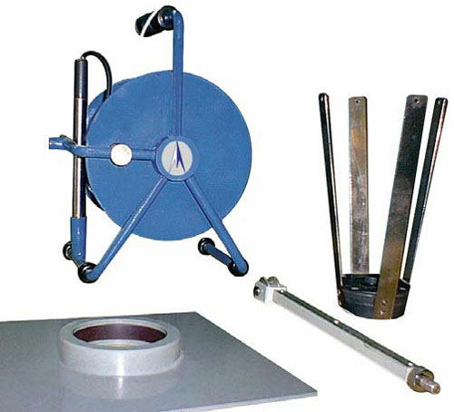
● It is used to measure and record the settlement in ground, earthen dam etc.
● It is worked on the principal which involves "Ring magnets" sliding on a access tube, and are fixed in the ground at the specified locations, where settlement movement is to be monitored.
● For underground – spring magnets are used
● For earthen embankment – Plate magnets used
● In case of underground applications the Spring magnets grouted into the rock or retained by a leaf spring arrow head or plate fixtures in soil or fill.
● A probe consisting of one or more read switches travels with the tube
● The read switch closes on entering the magnetic field and activates a Buzzer and indicator light on the reading instrument or cable drum.
● It can be used for horizontal and vertical installations
● System consist of rigid plastic pipes, extensometer, magnets, readout instrument with flat cable along with top cap and bottom plug.

Vi. Inclinometer:
● Inclinometer is used to determine the shear plane or lateral movements
● For measurements a plastic tube is installed in a borehole and the discoid between the ground or the concrete is filled with bentonite or cement grout.
● The inclinometer casing has four orthogonal grooves along the inside and these are used to guide an inclinometer probe along in order to survey the line of the inclinometer casing.
● An inclinometer probe contains orthogonal sensors that measure the angle that the body of the probe makes with vertical or horizontal.
● Inclinometer probes also have sprung wheels to hold them in the centre of the inclinometer casing as the survey is taking place.
Vii. Hanging and inverted pendulum:
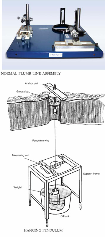
● These are use to monitoring the deflection in dam
● The Hanging pendulum uses a wire and a T-Square OR verniar microscope
● The upper end of the wire is anchored to the structure under observation
● A weight is suspended from the lower end is free to move in an oil tank, the oil is meant for acting as an damping agent, to damp the oscillations of the wire
● The wire remains vertical, but it moves with the structure, from which it is suspended therefore, the reading of the movement relative to the wire must be corrected for movement of the anchor
● Inverted and Hanging (Normal) pendulums are often together in the same structure, in which case all movements may be related to the inverted pendulum anchored at a depth in stable ground
● Verniar Microscopes are used for taking readings of the displacement.
