Unit 2
Gravity dam and arch dam
In gravity dam its own weight resists the forces exerted upon it.
It is permanent type of dam which require less maintenance.
It may be constructed either of masonry or of concrete.
These are suitable across gorges with very steep side slopes where earth dams might slip.
Gravity dams can be made upto any height in case of availability of good foundation.
Generally, gravity dams are straight type but may also be slightly curved in shape.
Components of gravity dams:
Note; Already discussed in unit 1, some of
Spillway: it is the structure made at the top of the dam to release the excess water of the reservoir to downstream side.
Drainage galleries: small openings left in the body of dam for various maintenance and repairing operation.
Sluice way: it is the structure made at the ground level for the silt clearance.
Favoring condition of gravity dam:
Gravity dams are built on generally stiff rock foundations
In rare cases also built on soil foundation.
In winter and spring, gravity dams help control the flow of melting snow in a river, and in summer they store water to provide it year-round to the neighboring land.
The bearing strength of the foundation limits the allowable position of the resultant force, influencing the overall stability.
Also, the stiff nature of the gravity dam structure is unforgiving to differential foundation settlement, which can induce cracking of the dam structure.
Forces acting on gravity dam:
- Weight of the dam
- Water force
- Uplift pressure
- Silt pressure
- Wave pressure
- Earthquake force
- Hydrodynamic force
- Ice pressure
i.Weight of the dam:
The weight of the dam is the major stabilizing force
It acts along the C.G. Of the cross section
Generally, unit length of dam is considered in the analysis purpose for weight of the dam
To calculate weight of dam the whole body is divided into the rectangles and triangles and weight of each part is calculated easily.
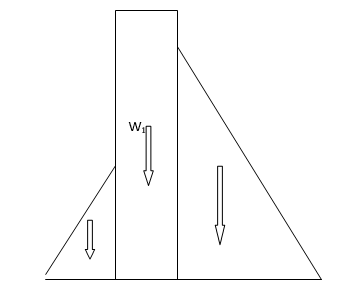
Weight of the dam = γc * (A1 + A2 + A3 ) x 1
Ii. Water force:
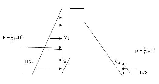
Water stored on the upstream is main destabilizing force.
Water stored on the downstream, is stabilizing force
V1,V2 and V3 are the wt. Of the water stored in respective prism
When upstream face of the dam is vertical then the water force acts horizontally.
Intensity of pressure varies triangularly, zero at the top and the maximum at the bottom.
If the upstream face is partly inclined and partly vertical than water pressure is resolved in horizontal and vertical components.
Iii. Uplift pressure:
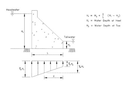
Water has tendency to seep through the voids and fissures of the material in the body of the dam and foundation material and through the joints between body of the dam and foundation
This seeping water exerts an Uplift pressure
It is defined as the upward pressure of water as it flows or seeps through the body of the dam or its foundation.
Case i. Uplift pressure without drainage gallery:
Case ii. Uplift pressure with drainage gallery:

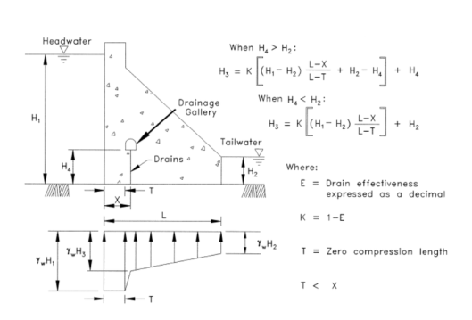
Uplift pressure reduces the wt. Of the dam, hence, it acts against the stability of the dam.
Uplift pressure below the drainage gallery is independent of its location
Uplift pressure can be controlled by constructing cutoff wall on the upstream face or drainage gallery near the upstream face.
v. Silt pressure
Silt deposited in the reservoir gets consolidated over a period of time and it helps to minimize uplift pressure on the body of the dam
If γsub is the submerged unit weight of silt and Φ is the angle of internal friction and hs is the height to which the silt is deposited, the silt pressure is given by;
Ps =  γsub hs2
Vi. Wave pressure:
Waves are fgenerated on the surface of rewservoir by wind blowing over the reservoir which cause a pressure towards downstream side
Wave pressure depends on wave height
Wave height may be given by;
Case I; if F<32 Km; then;
hw = 0.032 + 0.763 - 0.271F
 ¾
¾
Case II; if F≥32 km, then;
hw = 0.032
Where, F – fetch length in km
V- velocity of wind in kmph
hw = height of wave in m
Maximum pressure intensity :
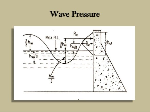
Pw = 2.4 γw hw at hw/8
P = 5/6* hw * 2.4 γw hw
P = 2 γw hw2 at 3/8 hw
Vi. Earthquake force:
Note: already discussed in unit 1. Please see this topic details in unit 1.
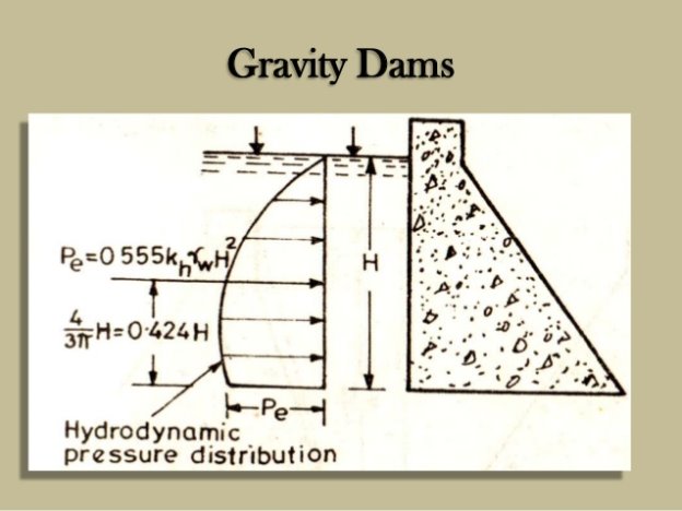
Vii. Hydrodynamic force:
If αh is acting upstream then an extra pressure force is excerted by water on the dam which is called as “hydrodynamic force”
According to Von-karma; Pe = 0.555khγwH2
Viii. Ice pressure:
In cold areas, dam face has to resist an extra pressure due to expansion of ice
Generally a value of 500 kN/m2 is applied to the face of the dam over anticipated area of contact of ice with the dam face
Ix. Wind pressure:
Wind pressure can be taken as 1-1.5 kN/m2 of exposed area
- Indian standard recommendations:
I. Load combination A (construction condition):
Dam completed but no water in reservoir and no tail water
II. Load combination B (normal operating condition):
Full reservoir elevation, normal dry weather tail water, normal uplift, ice and silt
III. Load combination C(flood discharge condition)
Reservoir of maximum flood pool elevation, all gates open, tailwater at flood elevation, normal uplift and silt
IV. Load combination D: combination A with earthquake
V. Load combination E: combination B with earthquake but no ice.
VI. Load combination F: combination C, but with extreme uplift
VII. Load combination G: combination D, but with extreme uplift
b. U.S.B.R. Recommendations:
- Normal load combination;
i. Normal water surface elevation, ice pressure, silt pressure and normal uplift. It is considered when the ice force may develop
ii. Normal water surface elevation, earthquake force, silt pressure and normal uplift.
Iii. Maximum water surface elevation, silt pressure and normal uplift
2. Extreme load combination
Maximum flood water elevation, silt pressure and extreme uplift with no drain in operation to release the uplift
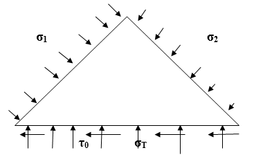
- Principal stress:
Considering an elementary triangular section at either the heel or at toe of the dam such that pressure intensities may be assumed uniform on its face.
σT =  +
+ 
We know that M= p.e and y = B/2; I = 1xB3
Hence, σT =  [1+
[1+ ]
]
σh = =  [1-
[1- ]
]
Principal stress σ1 is given by;
σT = {(σ1+σ2)/2}+{(σ1-σ2)/2}cos2α
Hence, σ1 = σT sec2α – σ2tan2α
II. shear stress:
by resolving all forces horizontally
τ0 = {(σ1-σ2)/2}sin2α
τ0 = (σT-σ2) tanα
Modes of failure in gravity dam:
- Overturning
- Sliding
- Crushing
- Tension
- Overturning:
this type of failure occur when the resultant force at any section cuts the base of the tow becomes clockwise or negative.
If the resultant cuts the base within the body of the dam, there will be no overturning.
Before overturning of gravity dam, other types of failure may occur such as cracking of upstream material due to tension, increase in uplift, sliding or crushing at toe
It the dam is considered to be safe in all these 4 failures than dam is safe against overturning
For stability, dam must be safe against overturning
F.O.S =  =
= 
II. Sliding:
For no sliding; μ∑V > ∑H
μ = 0.65-0.75
FOS =  >1
>1
Resisting force = μ∑V+B.q
FOS = 
In case of large dam for economic and precise design shear strength of the joint, which is an additional shear strength is also considered
To increase the shear strength, foundation is stepped at the base
Therefore, resisting force = μ∑V+B.q
Where, q is average shear strength of the hoint
B width of the base of the foundation
III.compression or crushing failure:
For safety in crushing failure; max. Compressive stress occur at toe and should be greater than the allowable compressive stress f for the foundation material.
Hence,  [1+
[1+ ] ≤ f
] ≤ f
When eccentricity e is equal to the B/6 then,
Ptoe =  [1+
[1+ ]
]
Ptoe = 2V/B
IV .Tension failure:
σh = =  [1-
[1- ]
]
for no tension; σh >0
[1- ] >0
] >0
e< B/6
Elementary profile of the gravity dam:
elementary profile of gravity dam is a right angle triangle with zero width at the top and bottom width equal to B.
shape of elementary profile of the dam is similar to the Hydrostatic pressure of the dam.
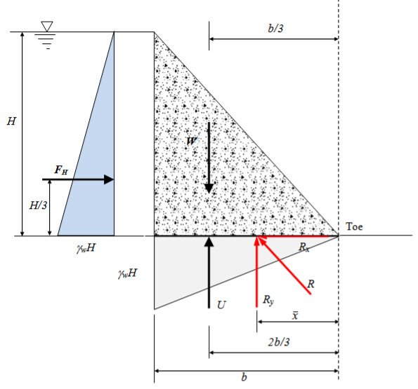
We consider, 3 main forces, acting on a gravity dam
- Weight of dam; W =
 B. H. γ c
 - Hydrostatic force; P =
 .γw.H2
 - Uplift force; U = =
 γw. C. B .H
Where C is the uplift intensity factor
For full reservoir; C = 1
For empty reservoir; C = 0
Case I. Reservoir empty condition;
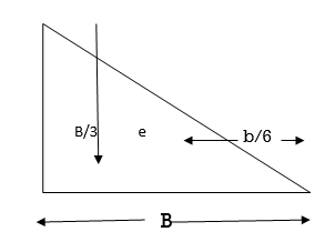
σH =  +
+ =
=  +
+ =
=  +
+
Hence, σH = 2W/B
σt =  -
- = =
= =  -
- = 0
= 0
Case II. Reservoir full condition
- No tension condition;
Let resultant of W,P and U passes through outermost point of middle third portion i.e. e = B/6
Moment about A; W x B/3 – U x B/3 = P x H/3
Putting the value of W, U and P in above equation;
 B. H. γ c x B/3 -
  γw. C. B .H x B/3 =
  .γw.H2 x H/3
B = 
2. For no sliding condition;
μ∑V > ∑H
μ(W-U) > P
μ( B. H. γ c -
  γw. C. B .H) >
  .γw.H2
B> 
3. Principal stresses;
σ1 = σT sec2α ; since we neglect tail water depth, σ2 = 0
Hence, σ1 = σT sec2α
=  [1+
[1+ ]
]
For no tension e = B/6
∑V = W- U
∑V =  B. H. γw (Gc-C)
σT = γw H (Gc-C)
Tanα = B/H; sec2α = 1+B2/H2
Hence, σ1 = γw H (Gc-C) (1+B2/H2)
For no tension; B/H = 
Hence, σ1 = γw H (Gc-C)(1+1/(Gc-C)
σ1 = γw H (Gc-C+1)
And shear stress = γw H
Discussed already in unit 1
Design method of gravity dam:
- Preliminary design of gravity is dam is done by 2-D method or gravity method
- In this method dam is supposed to made of with number of cantilever of unit length, acting independent of adjacent cantilever
- In elementary profile of dam it is seen that it has zero width at top and maximum at the bottom triangular in shape, but this triangular one is not practical nor necessary the most economic one.
Top width:
- Some width of a is provided at the top of the elementary profile of dam by that the resultant of the dam section will be shifted towards the upstream side in empty condition
- By providing a width at the top the batter at the u/s side is increased while at the downstream decreases
- Masonry volume at the top width is counterbalanced by the reduction in the d/s slope at lower ends
Free board:
- Free board is provided due to the height of waves
- Provide a free board equal to 3-4% of the height.
Multiple step method:
- For economic point of view, dam section is divided into the number of zones.
- All zones are designed to fulfill the stability criteria
Zone I:
- This is topmost portion of dam which is situated above the maximum reservoir level
- In case of no Ice, the height is controlled by free board requirement and the width is provided by the practical considerations for the economy of whole section
- In case of Ice, the height is fixed on the consideration of sliding of the zone due to ice pressure
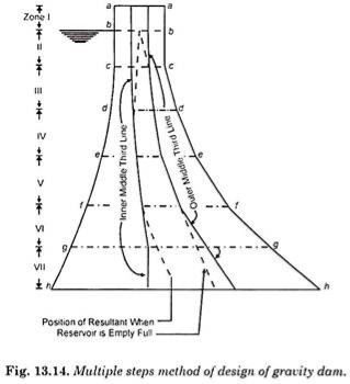
Zone II:
- In this zone the u/s and d/s both portion of dam remains vertical
- Position of the bottom plane cc is such that the resultant forces, in full reservoir condition passes through the outer third point of the plane cc
- When reservoir full, the resultant forces lies within the middle third throughout the zone II
Zone III:
- In this zone the u/s is remain vertical while d/s face is inclined
- Resultant coincide with the d/s extremity of middle third when reservoir full.
- Position of dd is kept such that in empty reservoir condition the resultant passes through the u/s middle third point
Zone IV:
- In this zone both u/s and d/s face are inclined and the line of resultant lie along the corresponding extremities of middle third
- Low dams lie within the limits of zone IV
NOTE: zone V, zone VI, zone VII are applicable only for high dams
Crack formation in gravity dam:
- Crack formation in dam is because of not proper temperature control; in that case, the large concrete blocks between the joints may crack due to high temperature gradient between the interior and the surface.
- These cracks are on the surface or deeper in the structure
- In internal structure of dam, the crack formation is due to the heat liberated due to the hydration of cement which gives rise the temperature gradient
Control of cracks in concrete dam:
- Crack control can be done by following steps;
- Pre-cooling of concrete:
Concrete is cooled before applying in the dam
This can be done by cooling the aggregate by refrigerated water, blowing air through them, cooling the sand and using refrigerated water for the concrete manufacturing
High cost preparing the concrete in this
2. Post cooling of concrete:
Post cooling is done by curing the concrete with refrigerated water through pipes embedded in concrete in each lift.
Cooling is done immediately, after placing first blocks of concrete
Resistance thermometers are embedded in the concrete to check the temperature
3. Using low heat cement
4. By lowering the percentage of cement in the concrete for the interior blocks, it is about 80% of the exterior
5. Restricting the height of lift upto 1.5 m
6. By providing sufficient time gap between laying of two successive vertical lifts
7. By providing contraction joint
These are horizontal joints
It is necessary to provide the construction joints when entire work of concreting of dam cannot be done in one stretch
In solid dam- construction joints limited to about 1.5 m
The height between two successive construction joints are called as lift.
For first layer on rock lift is limited to the 0.75 m
Keys:
Keys are providing invariably in the construction joint or horizontal to allow the transfer of shear stress from one block to another one.
Adjoining surface of each side of joint provided with a shape to interlocked together for the transfer of stresses.
Keyways may be of several types
Water seal or water stops:
These are provided in the transverse and longitudinal both types of joints
These may be of any metal: steel, annulated copper, monel, metal or sheet lead etc.
In non-yeilding foundations, metal water seals are provided
In yielding foundations, rubber water seals are provided
Chapter 2: Arch dam
Arch dam:
these are curved in plan and carries a major part of its water load horizontally to the abutments by arch action.
The water load is balanced by transferring it to the foundation by cantilever action.
The thrust, developed by water load carried by arch action
Classification of arch dam:
- Constant radius arch dam
- Variable radius dam
- Constant angle dam
1.Constant radius arch dam:
In this type of arch dam, the radius of prominent feature is constant
The constant radius, in most of the cases is refer to the upstream side
The arch centers for u/s face, d/s face, and the centre line of the horizontal arch rings at various elevations lies on straight vertical line
And this is passes through the horizontal arch ring centre of u/s face at crest.
It is used for U-shape canyons
2.Variable radius arch dam:
In these type of dam, the radii of intrados and extrados curves vary at various elevations, maximum at the top and the minimum at bottom of it’s
Used for V-shaped canyons
Has greater arch efficiency, resulting saving in concrete
Preferred over constant radius arch dam
3.Constant angle dam:
It is a special type of variable radius arch dam
Central angle of horizontal arch ring having same magnitude at all elevations
Constant angle arch needs only 42.6% of concrete which is requires for the constant radius arch dam, hence it is most economical