UNIT 3
Spillway and gates, hydraulic structures
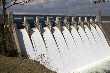
- Spillway is a waterway provided to dispose off surplus flood water from a reservoir after it has been filled to it’s maximum capacity.
- Spillway are provided for almost all the dams and these acts as safety valves for the dams
- A spillway may be located either within the body of the dam at one end of the dam entirely away from the dam in a saddle as an independent structure
- It is essential to provide a spillway of sufficient capacity so that the surplus water is discharged keeping the water level in the reservoir below some predetermined maximum level and no damage is done to the dam.

Classification of spillways:
- Straight drop spillway or free overfall spillway
- Ogee spillway
- Side channel spillway
- Chute spillway
- Conduit spillway
- Drop inlet spillway
- Siphon spillway
- Straight drop or free over-fall spillway:
- Free over fall spillway is most commonly used for low earth dams or earthen bunds
- This type of spillway is not suitable for high drops o yielding foundations, because the apron will be subjected to large impact forces at the point of impingement of the jet
- Ordinarily, free overfall spillways are used where the hydraulic drops from head pool to tailwater are not in excess of about 6m.

2. Ogee spillway:
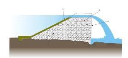
- It is widely used in concrete, masonry, arch and buttress dams.
- The shape of lower nappe of freely falling jet over a sharp crested weir can be determined by the principle of projectile
- The space between sharp crested weir and lower nappe is filled with concrete and the weir so formed has a profile similar to an ogee and hence called an ogee spillway.
- It the head of water over the spillway is more than the designed head, cavitation may occur
3. Side channel spillway:
- A side channel spillway is a type of spillway in which the control weir is placed along the side of and approximately parallel to the upper portion or crest of the spillway
- In a side channel spillway, the flow of water after spilling over the crest is turned by 900 such that it fow parallel to the weir crest
- This type of spillway is provided in narrow valleys where there are no side flanks of sufficient width to accommodate a chute spillway
4. Chute spillway:
- A chute spillway is the one which passes the surplus discharge through a steep sloped open channel, called a chute, placed either along a dam abutment or through a saddle.
- It is a simplest type of spillway which can be easily provided independently and at low casts.
5. Conduit spillway:
- In these type of spillways to pass the discharge under the dam, closed channel are used.
- It may be in form of vertical, horizontal tunnel, inclined shaft.
- Designed to flow partly full.
6. Shaft spillway:
- It is a type of spillway in which the water enters from the reservoir into a vertical shaft which conveys this water into a horizontal tunnel from where this water is discharged into a d/s river channel.
- Its discharge characteristics may vary with the range of head.
7. Siphon spillway:
- A siphon spillway is a closed conduit system formed in the shape of U, positioned so that the inside of the load of the upper passage way is at normal reservoir storage level
- Suction effect maintains a continuous flow due to the gravity pull of water in the down leg of the siphon
- It consists of five components;
- Inlet
- An upper leg
- A throat
- A lower leg
- An outlet
- An siphon breaker air vent is provided in order to stop the operation when the reservoir water surface is drawdown to control level
- Upper leg is formed as a bending convergent transition to join the inlet to a vertical throat section
- Lower leg is placed on an adverse slope to provide a more positive priming action by forming a flow certain which seals across the leg.
Heads in spillway:
Head: it is the vertical distance between water surface to the crest axis
- Design head:
It is that value of head for which the profile of spillway is designed.
Ii. Head due to velocity of approach:
Ha = Va2/2g
Iii. Total energy head:
It is the sum of the actual head and the head due to the velocity of approach
He = H + Ha
Components of spillway:
- Control structure
- Approach channel
- Discharge carrier
- Discharge channel
- Energy dissipater
- Control structure:
Regulates and control the surplus water from the reservoir
It does not allow the discharge of water below the fixed reservoir level
Ii. Approach channel:
It is the entrance structure and draw water from the reservoir and convey it to the control structures.
These may be curved or straight in plan
It ensure minimum head loss through and to obtain uniformity of flow over the control structure
Iii. Discharge carrier:
It is the waterway provided to convey the flows released from the control structure to the river below the dam, except in the case of arch dam wherein the discharge falls free from the crest or where the flow is released directly along the abutment hill side to cascade down the abutment face
These may be wide and narrow, long and short.
Iv. Discharge channel:
Provided to convey the water from bottom of the discharge carrier to the downstream flowing river
May be the downstream of the spillway itself.
v. Energy dissipater:
At the end of discharge carrier, water has greater velocity which may cause scour
So, energy dissipater are provided to prevent this scouring of the downstream face of spillway
In general, kinetic energy of the supercritical flow can be dissipated in two ways;
- By converting the supercritical flow into subcritical flow by hydraulic jump
- By directing the flow of water into air and then making it fall away from the toe of the structure.
Design of ogee spillway:
- Crest profile for vertical u/s face:
- Design criteria of downstream profile:
The downstream curve of the ogee has following equation:
x1.85 = 2. Hd0.85 .y
Where x and y = co-ordinates of the crest profile measured from the apex of the crest,
Hd = design head due to approach velocity
Ii. Design criteria of u/s crest profile:
u/s profile should have zero slope at the crest axis and tangential to the vertical face to ensure that along the surface there is no discontinuity
u/s shape given by following equation
y = [{0.724(x+0.270 Hd)1.85/Hd0.85} + 0.126 Hd – 0.4315 H d0.375(x+0.27 Hd)0.625
it should be noted that the shape of the u/s crest neither be too sharp nor too broad.
Iii. Crest profile for inclined u/s face:
Generally, nappe-shaped profile depends on:
- Head over crest
- Inclination of u/s face
- Height of the spillway crest above the stream bed
Shape can be represented by following equation;
xn = K . Hdn-1 . y
Value of k and n obtained from following table:
S.N. | Slope of u/s face | K | N |
1 | Vertical | 2.000 | 1.850 |
2 | 3 V to 1 H | 1.936 | 1.836 |
3 | 3V to 2 H | 1.939 | 1.810 |
4 | 3V to 3 H | 1.852 | 1.780 |
Discharge equation:
Q = Cd . Le . He3/2
Here; Cd = coefficient of discharge
Le = effective length = L – 2 (N Kp + Ka) He
He = total head = H + Ha
Energy dissipation below spillway:
In general, kinetic energy of the supercritical flow can be dissipated in two ways;
c. By converting the supercritical flow into subcritical flow by hydraulic jump
d. By directing the flow of water into air and then making it fall away from the toe of the structure.
Where the energy of flow is to be dissipated before the discharge is returned to the main river channel, the hydraulic jump basin is an effective device for reducing the exit velocity to a subcritical state.
In case, where discharge may be safely delivered directly to river, without providing dissipater, in that case jet is protected beyond the structure by deflector bucket.
Hydraulic jump computation:
Jump and flow characteristics depends on ;
- Discharge entering the basin
- Critical depth of flow
- Froude number parameter V/

- Head over the crest to total energy level
He = [ ]2/3
]2/3
2. Total energy level at u/s
u/s T.E.L. = crest level + He
3. Froude number
F = V/ 
Stilling basin:
It is a structure in which all or part of the energy dissipating action is confined.
In these first, kinetic energy causes turbulence and ultimately it is lost as heat energy
A hydraulic jump type stilling basin in which energy is dissipated by hydraulic jump
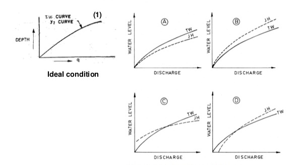
Correlation between tail water depth(T.W.D.) and hydraulic depth(y2):
- Tail water depth(T.W.D.) coincides with hydraulic depth
Ii. tail water depth(T.W.D.) lying above the y2 curve for all discharge
Iii. tail water depth(T.W.D.) lying below the y2 curve for all discharge
Iv. tail water depth(T.W.D.) lying above the y2 curve for small discharge and lying below for larger discharge
v. tail water depth(T.W.D.) lying above the y2 curve for larger discharge and lying below for small discharge

Spillway gates: requirements of gates
Spillway are mainly two types, one is controlled and other is uncontrolled
In controlled discharge can be controlled by using gates over its crest
These gates helps to store additional water during the low water flow. In floods duration, gates are opened and full use of spillway capacity can be made.
Some common type of gates:
- Flash board, stop log and needle:
Flash boards are used only for small spillway of minor importance
Flash boards consists of wooden panels supported by pins on the edges
The pins are supported on pipe sockets along the crest of the dam
Stop logs: these are horizontal timber planks spanning across piers having grooves.
Needle consists of wooden planks placed in inclined position, with lower ends resting in a keyway on the spillway crest and upper ends at the tops of a bridge girder.
b. Radial gates:
Its water supporting face is of steel plates, in the shape of sector of the circle properly braced and hinged at the pivot.
Thus, gate can be rotated about fixed horizontal axis
Load of the gate and water is carried by the bearing mounted on the piers
Gates can be lifted by the chains or rops
c. Drum gates:
Used for long spans
It consists of circular sector in cross section formed by skin plates attached to internal bearings
It is hinged at the centre of curvature in such a way that the entire sector may be raised above the crest or be lowered so that upper surface becomes coincident with the crest line
d. Vertical lift gate:
These are rectangular in shape and move vertically in their own plane
High frictional forces developed in the guides due to the hydrostatic pressure
Frictional force can be reduced by placing cylindrical rollers between the bearings surface of the gate and guides
e. Rolling gate
Hydropower structures:
Classified according to their function;
1.Run-off river plants:
There is no pond storage at the upsteam. It utilizes running river
Weir or barrage constructed across the river, to raise the water level slightly.
These are low head scheme, only adopted for perennial river
These plants are of two types:
- Those that utilize the varying flow and,
- Those that operate on the minimum available discharge and work throughout the year.
2. Storage plants;
These plants have a storage basin at the upstream side.
A dam is constructed and water is stored during the periods of excess supply.
In India, most of the plants are this category.
3.pumped storage plants;
A pumped storage plant stores power in the form of potential energy of water
Scheme consists of a storage reservoir at a higher level, and a turbine cum pump installation
The scheme is used to generate power only during the peak hours of demand
Classification of hydroelectric schemes:
- Low head scheme:
it is the one which uses head of less than about 15 metres.
It is essentially a run-off river scheme
A weir or barrage is constructed to raise the water
Ii. Medium head scheme:
Head between 15 to 60 metres
It is essentially a storage scheme
Dam is constructed to store the water
Iii. High head scheme:
Head of more than 60 meter.
A sufficient height dam is constructed to store water and ensure the supplies throughout the year.
Advantage:
It is fueled by water, hence clean energy
Impoundment hydropower creates reservoirs that offer a variety of recreational opportunities, notably fishing, swimming, and boating
Most hydropower installations are required to provide some public access to the reservoir to allow the public to take advantage of these
Opportunities
Other benefits may include water supply and flood control
Limitations:
Fish populations can be impacted if fish cannot migrate upstream past impoundment dams to spawning grounds or if they cannot migrate downstream to the ocean
Assessment of hydropower potential:
Let, Q = discharge in cumec, and
H = height of fall, in meter
Then the rate of work done is
= Q.w.H = 9.81 QH kN-m or kilo-watt
Let ηt be the efficiency of turbines, ηg be the efficiency of generator and η be the overall efficiency. The power generated by plant is given by;
P = 9.81 ηt ηg QH = 9.81 η QH kW
Gross head:
It is the difference in the elevation of the point of diversion of water for a hydel scheme and the point of return of water back to the stream.
Operating head:
It is the simultaneous difference between the elevations of the water surface in the forebay and the tail race after making due allowance for appraoch and exit velocity head
The net or effective head:
It is the head applied to the turbine and denotes the difference of head at the points of entry and exit of the turbine taking into account both the velocity and pressure heads
Terms related to hydropower plant:
- Forebay
- Intake structure
- Surge tank
- Penstocks
- Power house
- Turbines and governors
- Generators
- Transformers
- Transmission lines
- Forebay:
An enlarged body of water just in front of the intake
Main function is to store, temporarily, the water rejected by the plant when the load is reduced and to meet the instantaneous increased demand when the load is instantaneously increased
Ii. Intake structures:
The water is conveyed from the forebay to the penstocks through the intake structures
Trash rack: prevents the debris getting into the penstock
Rakes: to clear the trash rack
Ice removal equipment
Penstock closing gates with hoists
Iii. Penstocks:
Water through the storage reservoir is carried through penstocks or canal to the power house
Penstocks are the pipes of large diameter, usually made of steel in various form which carry water under pressure from the storage reservoir to turbine
Iv. Surge tank :
When the load on the turbine is reduced, the governor automatically closes the inlet gates partially, to reduce the inflow to the turbines