Unit - 4
Earth Dam & Diversion Head Works
Earth fill dam, also called Earth Dam, or Embankment Dam, dam built up by compacting successive layers of earth, using the most impervious materials to form a core and placing more permeable substances on the upstream and downstream sides.
They are logical choices for many sites where foundation conditions make concrete dams unsatisfactory. It should not be assumed that the construction of earth dam is a simple operation and that their design requires little more than rule-of-thumb criteria. Numerous failures of poorly designed earth embankments make it apparent that earth dams require as much engineering skill in their conception and construction as any other type of dam.
In no other type of dam are the construction and design procedures so interdependent; continuous field observations of deformations and pore water pressures are often made during the construction period to evaluate the initial design.
- Dirt can build up at dams, decreasing their effectiveness.
- Large scale wildlife habitat destruction due to river valley flooding.
- Dam construction forces people to leave their homes if the live in nearby areas.
- They are very expensive to build.
- It reduces areas for certain types of creation such as fisheries, camping , hunting etc.
- It is very difficult to allow subsequent rise in the height of a earth, unless specific provisions have been made in the initial design.
- It is unsuitable for spillways.
- Greater maintenance as compared to other dam.
There are three main types of earth dams, namely,
1) Homogeneous Dam
2) Zoned dam, arid
3) Diaphragm dam.
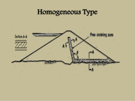
1- homogenous embankment type- If only one type of material is available then such embankments are made . Such type of dams preferred for low to moderate heights. The simple embankment is essentially homogeneous throughout, although a blanket of relatively impervious material may be placed on the upstream face. Levees are often simple embankments, but large dams are rarely constructed in this manner.
2- Zoned type dam-Zoned dams usually have a central zone of selected soil material, to form a relatively impermeable core, a transition zone along both faces of the core to prevent piping through cracks which may form in the core, and outer zones of more pervious material for stability. This construction is widely used in earth dams and is selected whenever suitable materials are available. Clay, even though highly impermeable, may not make the best core if it shrinks and swells too much. The most satisfactory cores are of clay mixed with sand and thin gravel.

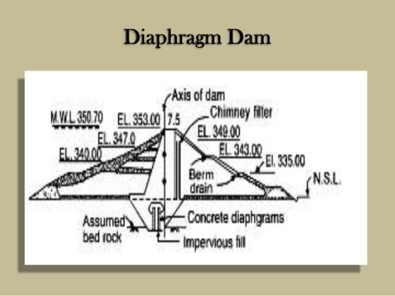
3- diaphragm type-Diaphragm type dams have a thin central section of concrete, steel, or timber which serves as a water barrier, while the surrounding earth or rock fill provides stability. Thin concrete sections are easily cracked by differential earth loads, and it is difficult to form a perfectly watertight barrier of steel or timber. In additon the diaphragm must he tied into bedrock or a very impermeable material if excessive under seepage is to be avoided.
Classification based on height -
1- Low dam
2- Medium dam
3- High dam
Low dam-
USBR defined small dam as one having maximum height < 15 m (50 ft).
Medium-
Intermediate sizes 40-70 ft
Large-
ICOLD defined large dam as a dam that follows one or more of following conditions. (Thomas 1976 P-0)
Dam height > 15 m (50 ft) measured from lowest portion of the general foundation area to the crest
A dam height 10-15 m but it compiles with at least one of the following condition:
- Crest of dam longer than 500 m
- Capacity of the resulting reservoir more than 1 million m3
- Maximum flood discharge more than 2000 m3/s (70,000 cfs)
- Dam has specially difficult foundation problems
- Dam is of unusual design
Classification of dam on the basis of materials-
Timber/steel dam
The bulk of the dam is made of timber braces with timber board facings. Such dams were mostly constructed by early gold miners in California USA for obtaining river water for separating gold dust and getting water power; such dams are not practically used any longer. The face of earthfill or rockfill dams may be also fitted with timber board for seepage control.
Gravity dam
Stability due to its mass. Dam straight or slightly curved u/s in plan (no arch action). The u/s face is vertical or nearly vertical, d/s sloping.
Classification on the basis of method of construction-
1- arch dam
2- gravity dam
3- arch gravity dam
4- embankment dam
Selection of type of earth dam-
There are various factors which affects selection of type of earth dams-
Topography
Topography dictates the first choice of the type of dam.
- A narrow U-shaped valley, i.e. a narrow stream flowing between high rocky walls, would suggest a concrete overflow dam.
- A low plain country, would suggest an earth fill dam with separate spillways.
- A narrow V-shaped valley indicates the choice of an Arch dam
Geological and Foundation Conditions
Geological and Foundation conditions should be thoroughly surveyed because the foundations have to carry the weight of the dam. Various kind of foundations generally encountered are
- Solid rock foundations such as granite have strong bearing power and almost every kind of dam can be built on such foundations.
- Gravel foundations are suitable for earthen and rock fill dams.
- Silt and fine sand foundations suggest construction of earth dams or very low gravity dams.
- Clay foundations are likely to cause enormous settlement of the dam. Constructions of gravity dams or rock fill dams are not suitable on such foundations. Earthen dams after special treatments can be built.
Availability of Materials
Availability of materials is another important factor in selecting the type of dam. In order to achieve economy in dam construction, the materials required must be available locally or at short distances from the construction site.
Spillway Size and Location
Spillway disposes the surplus river discharge. The capacity of the spillway will depend on the magnitude of the floods to be by-passed. The spillway is therefore much more important on rivers and streams with large flood potential.
Earthquake Zone
If dam is situated in an earthquake zone, its design must include earthquake forces. The type of structure best suited to resist earthquake shocks without danger are earthen dams and concrete gravity dams.
Height of Dam
Earthen dams are usually not provided for heights more than 30 m or so. For greater heights, gravity dams are generally preferred.
An earth dam has various components which are listed below-
- Foundation
- Core or (membrane)
- Shell
- Transition Filter
- Internal Drain
- Toe Drain
1- Foundation-It consists of either earth or rock and provides a support for the embankment and resists both vertical and horizontal loads. It also resists under seepage on the flow of water beneath the dam.
2- Core -It holds back the free water of the dam reservoir. It is located either at the centre or upstream from the centre of the dam. In case of rock fill dams, the core is provided on the upstream face. To resist the under seepage, the core is extended down into the foundation till an impervious layer of sufficient thickness is reached. The extension of the core into the foundation is termed as a cut off.
3- Shell-It provides structural support for the core and distributes the load over the foundation. The dams which are constructed of the same materials are called homogeneous dams. Small dams can suitably be constructed as homogeneous dams if the available materials are suitable.
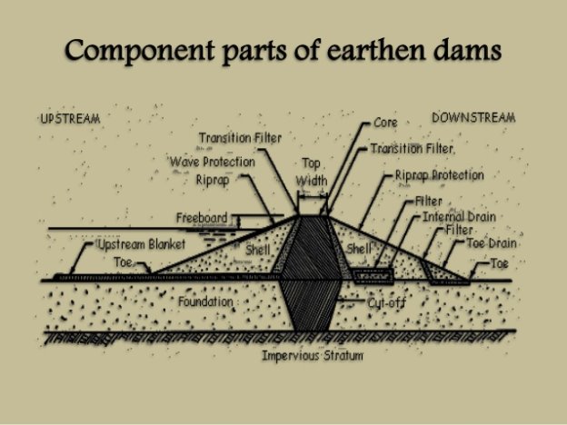
4- Transition filter-In core dams, a transition filter between the core and shell is generally provided to prevent the migration of the fine grained core materials into the pores of the coarse grained shell materials. In case of difference in particle sizes of the materials of the core and shell is small, the transition filter is omitted but in case of clay cover and rock or gravel shell, a transition filter is necessarily provided.
5- Internal drain-An internal drain is provided on the downstream side of the dam to carry away the seepage through the core and cut off, and also to prevent the saturation of the upper part of the downstream shell by rain on the dam.
6- Toe drain-A toe drain is provided at the downstream face of the shell. A riprap or grating is provided to cover the upstream face to prevent erosion or wash by waves.
Selection of earth dams-
The selection of earth dams depends on the various factors such as-
- Topography
- Geology and Foundation Conditions
- Availability of materials
- Spillway size and location
- Earthquake zone
- Height of the Dam
- Other factors such as cost of construction and maintenance, life of dam, aesthetics etc.
1. Sufficient spillway capacity and freeboard are provided so that there is no danger of overtopping of the dam
2. Seepage flow through the embankment is controlled so that the amount lost does not interfere with the objective of the dam and there is no erosion or sloughing of soil. In this respect, seepage line should remain well within the downstream face of the dam and the portion of the dam on downstream side of the impervious core should be well drained.
3. Uplift pressure due to the seepage underneath is not enough to cause piping
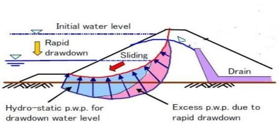
4. The slopes of the embankment are stable under all conditions of reservoir operation, including rapid drawdown and during steady seepage under full reservoir.
5. The stresses imposed by the embankment upon the foundation are less than the strength of material in the foundation with a suitable factor of safety.
6. The upstream face is properly protected ((stone pitching, riprap, revetment) against erosion caused by wave action, and the downstream face is protected (counter-booms, turfs) against the action of rain.
Stability analysis-
Every soil mass which has a slope at its end is subject to shear stresses on internal surfaces in the soil mass, near the slope. This is due to the force of gravity which tries to pull down the portions of the soil mass, adjoining the dope. If, however, the shearing resistance of the soil is greater than the shearing stress induced along the most severely stressed or critical
Internal surface, the slope will remain stable; and if on the other hand the shearing resistance of the soil, at any time after the construction of the slope becomes less than the induced shearing stress, the portion of the soil mass between the slope and the critical internal surface will slide down along this surface, until, the new slope formed by the sliding mass makes the shearing stress less than the shearing strength of the soil. The stability of slope of earthwork thus depends on the shear resistance or strength of the soil. * The well known method of investigating stability of slope is the Swedish method, devised by Swedish engineers in 1922, which is simple, and therefore, is more commonly used. In this method, the curved slip surface is taken to be an arc of a circle with a certain centre. There will be a number of such likely slip circles with their respective centres. It is necessary to pick up the most dangerous of critical slip circle which is the circle along which the soil has the least shear resistance. The centre of this circle is located by trial and error. Below are shown methods of locating the critical slip circle in the case of various types of soils, assuming that the soil slope is homogeneous structure i.e., it consists of one type of soil only.
a) Cohesive Soils
The slip circle for cohesive soils is shown in Figure 5.6. Let PHV be any slip circle with centre 01X, Ii s the distance of the centroid G of the area DPHV from the centre, O1.T he
Position of G can be obtained in the same manner as the centroid of an irregular plane area.
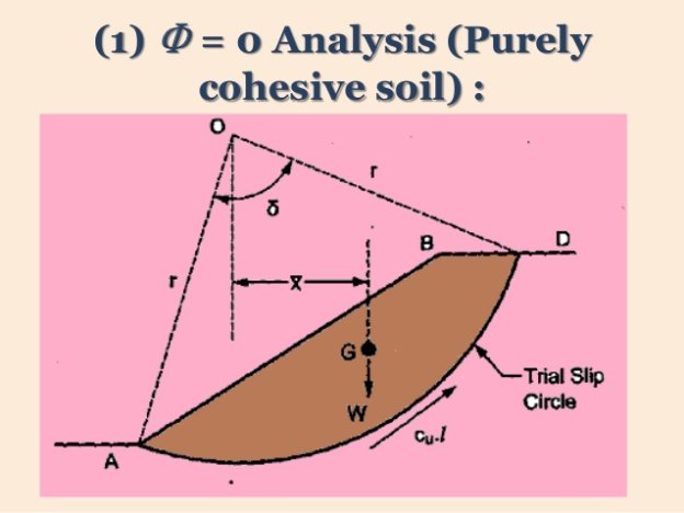
Actuating moment which may cause a slip along surface PHV = W x x 1 (kgm)
Where, W = weight of soil mass of area DPHV and length of 1 m.
For cohesive soils 4 = 0 and, its shearing resistance depends on cohesion only and is the same along the entire surface PHV.
The maximum resisting moment mobilized by the soil to prevent the likely occurrence of a slip = cohesive shear resistance developed along PHV.
Seepage control in earth dams- water seeping through the body of earth dam or foundation of earth dam may prove harmful to the stability of earth dam by causing softening or sloughing of the slopes due to development of pore pressures. It may also cause piping either body or through the foundation.
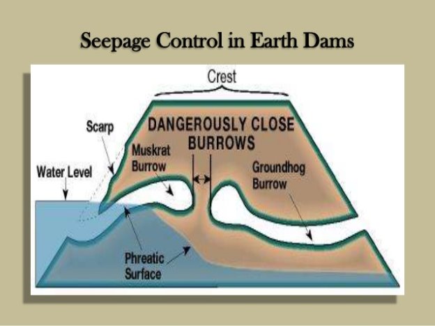
The seepage control is of various types-
1- Seepage control through embankment(by providing rock toe ,chimney drain, horizontal blanket)
2- Seepage control through foundations(by providing impervious cutoff, relief walls, drain trenches)
Seepage occurs through the body of all earth dams and all pervious foundations. The seepage through a pervious soil for 2-D flow is given by laplace eqn-

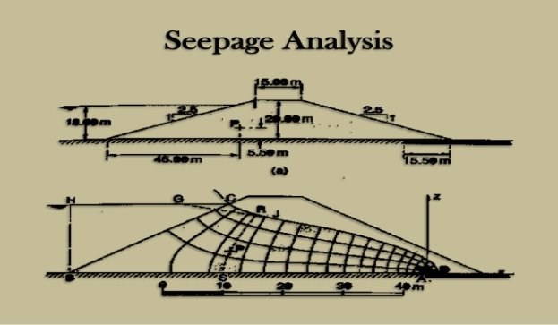
The amount of seepage can be easily computed for the flow net. Let us assume that soil is istropic i.e permeability is constant in all directions (Kh=Kv)
The seepage rate (q) can be computed from the flownet, by using darcy law and applying continuity equation-
q=K.H.Nf/Nd
Nf= no. Of flow nets
Nd= no of flow drops
K= permeability
Phreatic line in the earth dams-
Phreatic Line in Earthen Dam. Phreatic line is the top flow line which separates saturated zone from unsaturated zone and below which positive hydrostatic pressure exists in the dam section. Along the phreatic line, the atmospheric pressure exists.
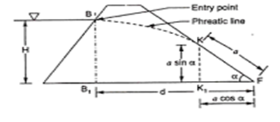
It gives us a divide line between the dry or wet soil . The soil above the line is Said to be dry while the soil below the line is said to be wet(submerged).
Every soil mass which has a slope at its end is subject to shear stresses on internal surfaces in the soil mass, near the slope. This is due to the force of gravity which tries to pull down the portions of the soil mass, adjoining the dope. If, however, the shearing resistance of the soil is greater than the shearing stress induced along the most severely stressed or critical
Internal surface, the slope will remain stable; and if on the other hand the shearing resistance of the soil, at any time after the construction of the slope becomes less than the induced shearing stress, the portion of the soil mass between the slope and the critical internal surface will slide down along this surface, until, the new slope formed by the sliding mass makes the shearing stress less than the shearing strength of the soil. The stability of slope of earthwork thus depends on the shear resistance or strength of the soil. * The well known method of investigating stability of slope is the Swedish method, devised by Swedish engineers in 1922, which is simple, and therefore, is more commonly used. In this method, the curved slip surface is taken to be an arc of a circle with a certain centre. There will be a number of such likely slip circles with their respective centres. It is necessary to pick up the most dangerous of critical slip circle which is the circle along which the soil has the least shear resistance. The centre of this circle is located by trial and error. Below are shown methods of locating the critical slip circle in the case of various types of soils, assuming that the soil slope is homogeneous structure i.e., it consists of one type of soil only.
a) Cohesive Soils
The slip circle for cohesive soils is shown in Figure 5.6. Let PHV be any slip circle with centre 01X, Ii s the distance of the centroid G of the area DPHV from the centre, O1.T he position of G can be obtained in the same manner as the centroid of an irregular plane area.
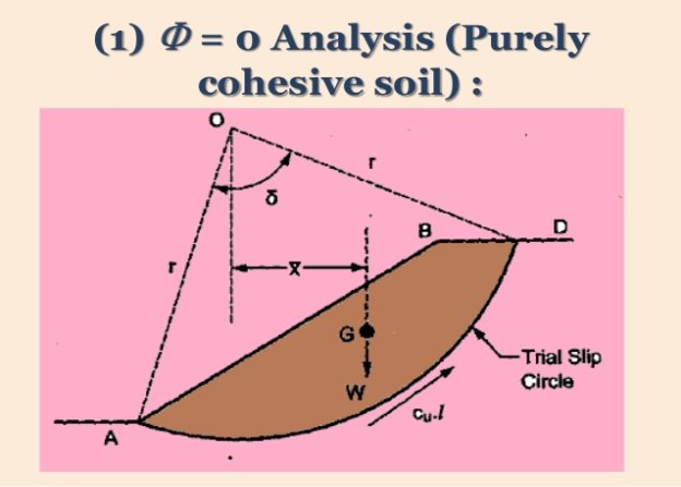
Actuating moment which may cause a slip along surface PHV = W x x 1 (kgm)
Where, W = weight of soil mass of area DPHV and length of 1 m.
For cohesive soils 4 = 0 and, its shearing resistance depends on cohesion only and is the same along the entire surface PHV.
The maximum resisting moment mobilized by the soil to prevent the likely occurrence of a slip = cohesive shear resistance developed along PHV.
Forces in the dam-
- Water pressure
- Uplift pressure or seepage loads
- Earthquake forces
- Self weight of the dam
- Silt pressure
- Wave pressure
- Ice pressure
Method of stability analysis of earth dam-
An earthen dam usually fails due to sliding of large soil mass from a curved surface. From several investigations, it has been concluded that the sliding of curved surface takes place along its slip surface, which is normally close to the cylindrical shape, i.e. when cross section is in the form of arc.
There have been developed various methods for stability analysis of earth dam. All of them are based on the shearing strength of the soil and certain assumptions with respect to the characteristics of embankment failure.
The most common methods are described as under:
1- Swedish circle method
2- Loaction of centre of slip circle
3- Stability of downstream slope during steady seepage
4- Stability of upstream slope during sudden draw down.
This method is used to examine the stability of slope of earthen dam. It assumes that the shape of failure plane is in the form of cylindrical arc, and the centre of the possible failure are is known.
In this method to analyse the slope stability, the total earth fill is divided into several vertical segments called slice, which are equally spaced, though it is not necessary. Depending on the accuracy desired, normally six to twelve slices are sufficient. The forces between the slices are considered negligible; and it is also assumed that each slice acts independently as a vertical soil column of unit thickness and width (b). The weight W of each slice acts at its centre point.
Let ‘O’ is the centre, r is the radius of possible slip circle and length of arc DB is divided into 7 slices of equal width (b). The weight of these seven slices are W1, W2, W3…W7 as shown in Fig. 18.13. The weight (W) has two components; one is normal component (N = W cos α) and other is tangential component (T = W sin α), in which α is the slope angle with the horizontal.
v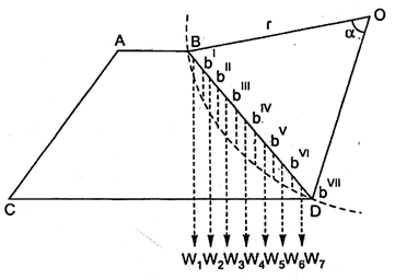
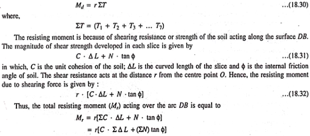
The normal component (N) passes through the centre of the slip circle, i.e. through point (O), hence it does not involve any moment on the slice, but the tangential component (T) causes a disturbing moment, equal to (T. r), where r is the radius of the slip circle. The tangential component of few slices also creates resisting moment, especially when value of T is taken as negative.
If Md is the total disturbing moment, then it is equal to the algebraic sum of all tangential moments, given as under –
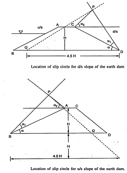
Hit and trial method is used to determine the location of centre of slip circle, in which several slip circles are assumed; and factor of safety for each, is calculated. A slip circle which yields lowest value of factor of safety, is considered to be the critical slip circle. For reducing the number of trials, Fellenius has suggested the method for drawing a line (PQ) on which the locus of critical circle is fixed.
The procedure to locate the line PQ for the downstream and upstream slopes of the embankment is shown in Fig. (a) and (b), respectively. The point Q is obtained by taking the co-ordinate as (4.5 H, H) from the toe of the dam, shown in Fig..
After determining the position of locus, the critical slip circle is drawn by considering the following points:
1. Critical arc should be passed through the toe of the slope, except for very small value of ɸ.
2. If there exists a hard stratum relatively at a shallow depth under the dam, then the critical arc should not cross this stratum, but can be tangential to it.
3. For very small value of ɸ ranging from 0 to 15°, the critical arc should pass below the toe of the slope; and centre of the critical arc should be on a vertical line drawn through the centre of the slope, as shown in Fig.
The maximum load that can be sustained by shallow foundation elements due to the bearing capacity is a function of the cohesion and friction angle of bearing soils as well as the width B and shape of the foundation. The net bearing capacity per unit area, qu, of a long footing is expressed as:

Where
(alpha)f= 1.0 for strip footings and 1.3 for circular and square footings
cu= Un-drained shear strength of soil
(sigma) vo = effective vertical shear stress in soil at level of bottom of footing
(beta)f = 0.5 for strip footings, 0.4 for square footings, and 0.6 for circular footings
gamma =unit weight of soil
B=width of footing for square and rectangular footings and radius of footing for circular footings
Nc, Nq, N=bearing-capacity factors, functions of angle of internal friction (phi)
For undrained (rapid) loading of cohesive soils, phi=0
thus equation reduced to
qu= N ‘c cu
where
N’c=(alpha)fNc
Assumptions made
1) The equation is based on an infinitely long strip footing.
2) The soils to be homogeneous throughout the stressed zone.
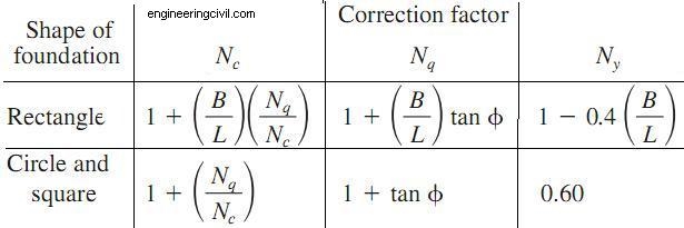
The values of correction factor are listed below-
Causes of failure in earth dams-
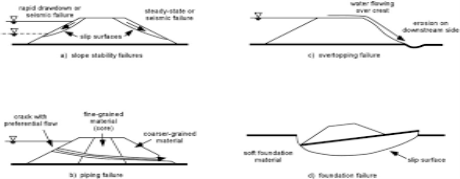
Failure of earth dams may be three types-
1- Hydraulic failures
2- Seepage failures
3- Structural failures
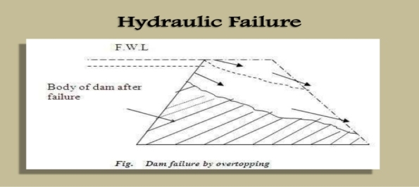
1-Hydraulic failures-failure of about one third of earth dams is attributed to them. They are produced by surface erosion of the dam by water. Also included are washouts from overtopping (Fig),wave erosion of upstream face, scour from the discharge of the spillway, etc. and erosion from rainfall.
2-Seepage failure- Seepage through earthen dam is casual but it is considered as harmless when it is limited or controllable. If it is uncontrollable or concentrated seepage then there occurs problems such as piping and sloughing. 1 out of every 3 failed dam cases have seepage failures.
- Piping through Foundation
- Piping through Dam body
- Sloughing of Downstream toe
When the foundation of earthen dam consists gravel or coarse sand layers or fissures etc., the water from upstream will seep through it. The seepage at higher gradient erode the soil and creates hollow spaces inside the foundation which is called as piping through foundation.

Piping through dam body will occur due to seepage of water through dam body. This is mainly due to insufficient compaction of soil used for the dam, faulty construction of dam, shrinkage cracks, animal burrows in dam body, etc.
IF the downstream toe of dam gets saturated by piping or any seepage action, it will get eroded and forms small slide or small slump. The slump will create steeper face which again gets eroded due to seepage and form slump again. This progressive removal of saturated soil is called sloughing. This will finally lead to removal of soil from whole downstream face and makes the dam body thin resulting failure of dam.
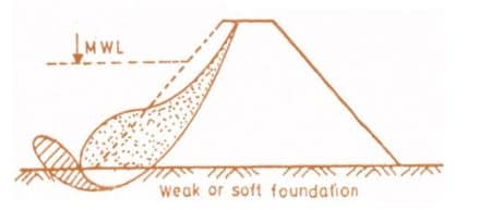
3-Strucutral failure-Another cause for failure of earthen dams is structural failures. About 1/4th of earthen dams have failed due to structural failures.
- Sliding of Foundation
- Sliding of Embankment
Sliding of foundation is nothing of sliding of whole dam body. This occurs when the foundation contain soft clay, fine silt etc. This type of foundation material will cause sliding of entire dam which will cause cracks on the top of embankment and forms mud waves near the upstream heel.
Sliding of embankment occurs when the slope of embankment is too steep. When the reservoir water level is suddenly draw down, then there is a chance of sliding of upstream slope. Similarly when the reservoir is at full level, then there is a chance of downstream slope failure.
Introduction-An irrigation canal takes its supplies from a river or a stream. In order to divert water from the river into canal it is necessary to construct certain works or structures across the river and at the head of the off taking canal. These works are known as Diversion headworks, or headworks.
- They raises the water level in the river so that the commanded area is increased
- They regulates the supply of water into the canal
- They controls the entry of silt into the canal
- They will provide some storage of water for a short period
- They reduces the fluctuations in the level supply in the river
1- The river section at the site should be narrow and well defined.
2- The river banks should be well defined.
3- The valuable land should not be submerged when the weir or barrage is constructed.
4- The elevation of the site should be much higher than the area to be irrigated.
5- The site should be easily accessible by roads or railways.
6- The materials of construction should be available in vicinity of the site.
7- The site should be not be far away from the command area of the project, to avoid transmission loss.
Layout of diversion head works-
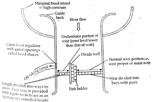
Layout of head works as shown in fig given below-
Components of diversion head works-
The various components of diversion headworks are as follows:
- Weir or Barrage
- Divide wall or divide groyne
- Fish ladder
- Undersluices or scouring sluices
- Silt excluder
- Canal head regulator
- River training works such as Marginal bunds and Guide bunds
1- Weir-
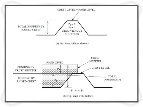
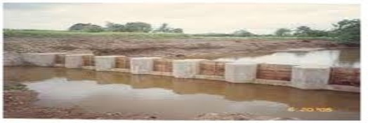
A weir is a structure constructed across a river to raise its water level and divert the eater into the canal. On the crest of the weirs usually shutters are provided so that part of the raising up of water is carried out by shutters. During floods the shutters may be dropped down to allow water to flow over the crest of the weir. Weir is usually aligned at right angles to the direction of flow of the river.
2- Divide wall or divide groyne- A divide wall is a long masonry or concrete wall or groyne (an embankment protected on all sides by stone or concrete blocks) which is constructed at right angles to the axis of the weir to separate the undersluices from the rest of the weir. If two canals take off, one on either side of the river, then two divide walls are required, one on each side. The top width of the divide wall is about 1.5 to 2.5m. The divide wall extends on the upstream side up to a distance little beyond the beginning of the canal head regulator and on the downstream side up to the end of the loose protection.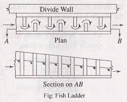
3- Fish ladder-Large rivers have various types of fish, many of which are migratory. They move from one part of the river to another according to the season. In our country generally fish move from upstream to downstream in the beginning of winter in search of warmth and return upstream before monsoon for clearer water. Due to the construction of a weir or barrage across the river such migration of the fish will be obstructed and if no arrangement is made in the weir or barrage for this migration, large scale destruction of the fish life may take place in the river.
4- Under sluices or scouring sluices-They maintain a deep channel in front of head sluice and dispose off heavy silt and a part of flood discharge on the downstream side of the barrage or weir.
5- Silt excluder-Silt excluders are a type of silt control device which functions to exclude silt from water to entering the canal. These devices are particularly provided on the river bed in front of the head regulator. A silt excluder usually consists of a number of rectangular tunnels resting on the floor of the undersluice pocket. The bottom portion of the tunnels is formed by the floor of undersluice pocket. The top level portion of the roof of tunnel is kept same as the level of the crest or sill of the head regulator. The tunnels are constructed with variable lengths. The tunnel nearest to the crest is of same length as the length of the head regulator. But all other successive tunnels have a decreasing length.
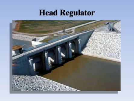
6- Canal head regulator-A head regulator is structures constructed at the head of a canal off take from a reservoir behind a weir or a dam. It may consist of a number of spans separated by piers and operated by gates.
Functions
1- To make the regulation of supply in the canal easy.
2- To shut out river floods.
3- To control the silt entry into the canal.
7- River training works-River training is defined as the various measure adopted on a river to stabilize the river channel along a certain cross section for a particular alignment. These measures are adopted because the rivers in alluvial plane frequently alter their courses and subsequently cause damage to the land and property adjacent to them. Some of the major river training works are explained as below:
Marginal bunds
Marginal bunds or levees are the earthen embankments which are provided to confine the flood water from the river within an allowable cross-section and in between the embankments. Thus the spreading of flood water beyond these marginal bunds is prevented.
Guide banks or Guide bunds
The guide bunds are also a type of earthen embankments provided to confine the flood water of alluvial rivers within a reasonable length of waterway and provide a straight and non-tortuous approach towards the constructions works across the river. They are also used to prevent the river from changing its course and outflanking the construction work. In India the guide banks were first designed by Bell and hence these are also known as Bell’s bunds. The initial design by Bell was later modified by Spring and Gales and this modified design is commonly adopted these days.
The complete design of weir can be divided into two types-
1- Hydraulic design
2- Structural design
Hydraulic Design for the Weir. The 'hydraulic design' involves determining the section of the weir and the details of its u/s cutoff, crest, glacis, floor, d/s cutoff, protection works u/s and d/s, etc. The hydraulic design of weirs on permeable foundations may be classified into : (i) Design for Sub-surface Flow; and (ii) Design for Surface Flow. The. Effects of sub-surface flow or seepage flow on the stability of a hydraulic structure founded on permeable foundations have been thoroughly described earlier and the same hold good for weirs or barrages. Khosla 's method of independent variables is invariably used for determining the uplift pressures exerted by the seeping water on the floor of the' weir. The safety of the structure against piping has to be checked by keeping the exit gradient within safe limits. The maximum uplift pressure shall occur when the pond is full and there is no water flowing down the weir. But when flood water passes over the weir, entirely new conditions are superimposed. The formation of hydraulic jump causes uplift or unbalanced head in the jump trough, which may be larger than that under steady seepage, as explained below.
Length of pucca floor- The total length of the pucca floor is mainly governed by the exit gradient considerations. For a safe exit gradient and a depth of downstream cut-off suitable from scour considerations, the length of the horizontal floor 'b' can be worked out as b =a· d (a is known when GE is fixed). The main turbulence of the hydraulic jump is generally confined to a length equal to five times the jump height. Hence, a pucca floor equal to or more than 5 (y2 - y1) in length is provided after the lowest point of jump formation, i.e. the endpoint of glacis. The glacis should-be sloped down at a slope of3;1 to 5,:1) for maximum dissipation of energy coupled with economy and stability of the jump. The top width of the crest is generally kept as 2.0 to 3.0 metres from practical considerations, and the upstream slope to the crest is kept as 1 : 1 to 3 : 1. The length of the upstream floor may be adjusted so as to provide the necessary total floor length b, calculated above, as b = a.d. · By providing a deeper d/s cut-off;. It is possible to reduce the floor length 'b' and vice,-versa, and hence b and d can be mutually adjusted to provide the most economical and suitable combination and to keep a safe exit gradient.
- It directly depended upon the possibilities of sub soil. As we know that water may seeps through their weir base and subsoil through it. The head loss by creeping water is directly proportional to distance it travels along the base of weir profile.
- The creep length must be made as big as possible so as to prevent the piping action. This can be achieved by providing deep vertical cut offs or vetical sheet piles.
According to Bligh's Theory, the percolating water follows the outline of the base of the foundation of the hydraulic structure. In other words, water creeps along the bottom contour of the structure. The length of the path thus traversed by water is called the length of the creep. Further, it is assumed in this theory, that the loss of head is proportional to the length of the creep. If HL is the total head loss between the upstream and the downstream, and Loss the length of creep; then the loss of head-per unit of creep length (HL/L) is called hydraulic .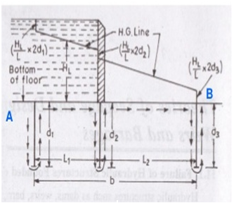


Lane theory of seepage-Bligh’s , in his theory had calculated the length of the creep, by simply adding the horizontal creep length and the vertical creep length, thereby making no' distinction between the two creeps. However, Lane, on the basis of his analysis carried out on about 200 dams all over- the -world, stipulated-that the horizontal creep is less effective in reducing uplift (or in causing loss of head) than the vertical creep. He, therefore, suggested a weightage factor one third for the horizontal creep, .as against 1 for the vertical creep.

The seeping water does not creep along the bottom contour of pucca floor as stated -by Bligh, but on the other hand, this water moves along a set of stream-lines as shown in Fig. 11.3. This steady seepage ln a vertical plane for a homogeneous soil can be expressed by Laplacian equation.

Khosla theory of independent variables-In order to know as to how the seepage below the foundation of a hydraulic structure is taking place, it is necessary to plot the flownet. In other words, we must solve the Laplacian equations. This can be accomplished either by mathematical' solution of the Laplacian equations, or by Electrical analogy method, or by graphical sketching by adjusting the streamlines and equipotential lines w.r.t. The boundary conditions. These are complicated methods and are time consuming. Therefore, for designing hydraulic structures such as weirs or barrages on pervious foundations, Khosla has evolved a simple, quick· and an accurate approach, called Method of Independent Variables.
The complete design of weir can be divided into two types-
- Hydraulic design
- Structural design
Hydraulic Design for the Weir. The 'hydraulic design' involves determining the section of the weir and the details of its u/s cutoff, crest, glacis, floor, d/s cutoff, protection works u/s and d/s, etc. The hydraulic design of weirs on permeable foundations may be classified into : (i) Design for Sub-surface Flow; and (ii) Design for Surface Flow. The. Effects of sub-surface flow or seepage flow on the stability of a hydraulic structure founded on permeable foundations have been thoroughly described earlier and the same hold good for weirs or barrages. Khosla 's method of independent variables is invariably used for determining the uplift pressures exerted by the seeping water on the floor of the' weir. The safety of the structure against piping has to be checked by keeping the exit gradient within safe limits. The maximum uplift pressure shall occur when the pond is full and there is no water flowing down the weir. But when flood water passes over the weir, entirely new conditions are superimposed. The formation of hydraulic jump causes uplift or unbalanced head in the jump trough, which may be larger than that under steady seepage, as explained below.
Length of pucca floor- The total length of the pucca floor is mainly governed by the exit gradient considerations. For a safe exit gradient and a depth of downstream cut-off suitable from scour considerations, the length of the horizontal floor 'b' can be worked out as b =a· d (a is known when GE is fixed). The main turbulence of the hydraulic jump is generally confined to a length equal to five times the jump height. Hence, a pucca floor equal to or more than 5 (y2 - y1) in length is provided after the lowest point of jump formation, i.e. the endpoint of glacis. The glacis should-be sloped down at a slope of3;1 to 5,:1) for maximum dissipation of energy coupled with economy and stability of the jump. The top width of the crest is generally kept as 2.0 to 3.0 metres from practical considerations, and the upstream slope to the crest is kept as 1 : 1 to 3 : 1. The length of the upstream floor may be adjusted so as to provide the necessary total floor length b, calculated above, as b = a.d. · By providing a deeper d/s cut-off;. It is possible to reduce the floor length 'b' and vice,-versa, and hence b and d can be mutually adjusted to provide the most economical and suitable combination and to keep a safe exit gradient.
Design of Protection Works. Protection works are required on the upstream as well as on the downstream in order to obviate the possibility of scour hole travelling close to the pucca floor of the weir and to relieve any residual uplift pressure through the filter. The arrangement consists of
1- inverted filter
2- Launching apron

Reference Books
- Design of Small Dams- United States Department of the Interior, Bureau of Reclamation revised reprint 1974, Oxford and IBH Publishing Co.
- Irrigation and Water Resources Engineering- Asawa G.L- New Age International (P) Ltd. Publishers, first ed, 2005.
- Engineering for Dams- CreagerW.P, Justin J.D, Hinds J -Wiley Eastern Pvt. Ltd., New Delhi, 1968
- Irrigation Engineering and Hydraulic Structures- Garg S.K- Khanna Publishers N.D. 13th ed, 1998.
- Hydraulic Structures, Vol. 1. & Vol. 2- Grishin M.M- Mir Publishers, Moscow, 1982.
- Design Textbook in Civil Engineering: Volume Six: Dams- Leliavsky, Serge – Oxford and IBH Publishing Co. Pvt. Ltd., 1981.
- Roller Compacted Concrete Dams- MehrotraV.K- Standard Publishers Distributors, Delhi, 1st ed, 2004. 8. Irrigation, Water Resources and Water Power Engineering- Modi, P.N. - Standard Book House, New Delhi, 2nd ed, 1990.
- Earth and Earth Rock Dams- Sherard J.L, Woodward R.J. - John Wiley and Sons, inc. 1963.