Unit –6
Cross Drainage Works & River Training Structure
A cross drainage work is a structure carrying the discharge from a natural stream across a canal intercepting the stream. Canal comes across obstructions like rivers, natural drains and other canals. Cross drainage works can be avoided in two ways:
- By changing the alignment of canal water way
- By mixing two or three streams into one and only one cross drainage work to be constructed, making the structure economical.
The following points should be considered while selecting the site of a cross-drainage work:
- At the site, the drainage should cross the canal alignment at right angles. Such a site provides good flow conditions and also the cost of the structure is usually a minimum.
- The stream at the site should be stable and should have stable banks.
- For economical design and construction of foundations, a firm and strong sub-stratum should exit below the bed of the drainage at a reasonable depth.
- The site should be such that long and high approaches of the canal are not required.
- The length and height of the marginal banks and guide banks for the drainage should be small.
- In the case of an aqueduct, sufficient headway should be available between the canal trough and the high flood level of the drainage.
- The water table at the site should not be high, because it will create De-watering problems for laying foundations.
- As far as possible, the site should be selected d/s of the confluence of two streams, thereby avoiding the necessity of construction of two cross-drainage works.
- The possibility of diverting one stream into another stream upstream of the canal crossing should also be considered and adopted, if found feasible and economical.
The following data are required for the design of cross drainage work-
1- Canal- full supply discharge ,bed width,full supply depth,side slopes, full supply level, bed level,rugosity constant.
2- Drainage channel- extent and nature of drainage area, maximum annual rainfall, maximum flood level, longitudinal section of stream, intensity of rainfall, cross sections
3- Design flood- The design discharge of the drainage should be selected considering various factors such as size of drainage, size of canal,type of cross drainage works.
4- Waterways- waterway for cross drainage works is fixed from hydraulic and economic considerations. Topography of the site, slope of the drainage channel.
There are three types of cross drainage works structures:
Type – 1: Cross drainage work carrying canal over the drain
The structures falling under this type are
- Aqueduct
- Syphon Aqueduct
Type – 2: Cross Drainage work carrying Drainage over the canal
The structures falling under this type are
- Super passage
- Canal Syphon
Type –3: Cross drainage works admitting canal water into the canal
The structures falling under this type are
- Level Crossing
- Canal inlets
The above are discussed below here-
TYPE -1 (HFL<FSL)
Aqueduct:
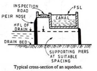
In an aqueduct, the canal bed level is above the drainage bed level so canal is to be constructed above drainage.
A canal trough is to be constructed in which canal water flows from upstream to downstream. This canal trough is to be rested on number of piers. The drained water flows through these piers upstream to downstream.
The canal water level is referred as full supply level (FSL) and drainage water level is referred as high flood level (HFL). The HFL is below the canal bed level.
Aqueduct is similar to a bridge, instead of roadway or railway, canal water are carried in the trough and below that the drainage water flows under gravity and possessing atmospheric pressure.
Syphon Aqueduct:
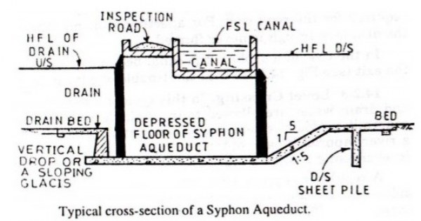
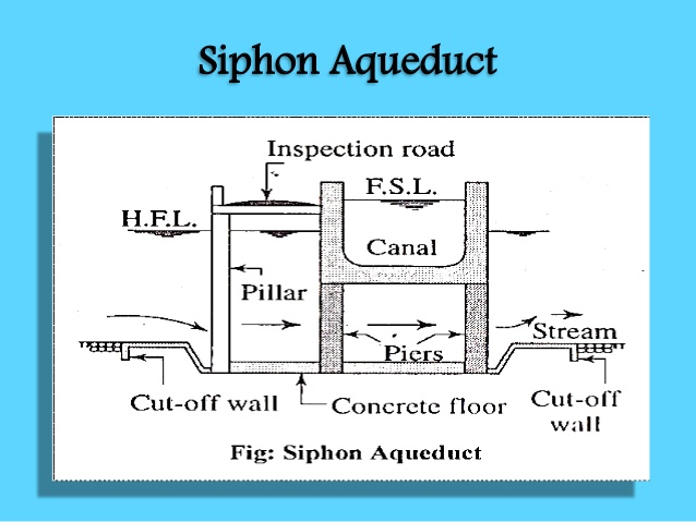
In a syphon aqueduct, canal water is carrier above the drainage but the high flood level (HFL) of drainage is above the canal trough. The drainage water flows under syphonic action and there is no presence of atmospheric pressure in the natural drain.
The construction of the syphon aqueduct structure is such that, the flooring of drain is depressed downwards by constructing a vertical drop weir to discharge high flow drain water through the depressed concrete floor.
Syphonic aqueducts are more often constructed and better preferred than simple Aqueduct, though costlier.
Super Passage:
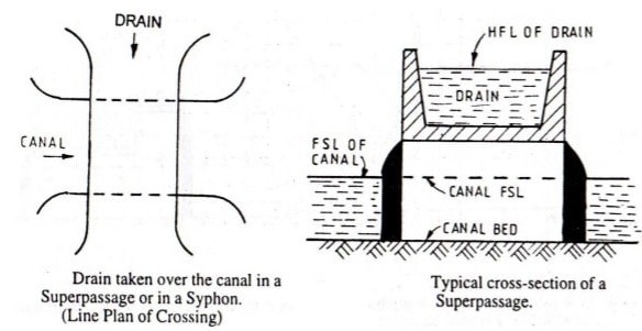
Super passage structure carries drainage above canal as the canal bed level is below drainage bed level. The drainage trough is to be constructed at road level and drainage water flows through this from upstream to downstream and the canal water flows through the piers which are constructed below this drainage trough as supports.
The full supply level of canal is below the drainage trough in this structure. The water in canal flows under gravity and possess the atmospheric pressure. This is simply a reverse of Aqueduct structure.
Canal Syphon:
In a canal syphon, drainage is carried over canal similar to a super passage but the full supply level of canal is above than the drainage trough.so the canal water flows under syphonic action and there is no presence of atmospheric pressure in canal.
When compared, super passage is more often preferred than canal Syphon because in a canal Syphon, big disadvantage is that the canal water is under drainage trough so any defective minerals or sediment deposited cannot be removed with ease like in the case of a Syphon Aqueduct.
Flooring of canal is depressed and ramp like structure is provided at upstream and downstream to form syphonic action. This structure is a reverse of Syphon aqueduct.
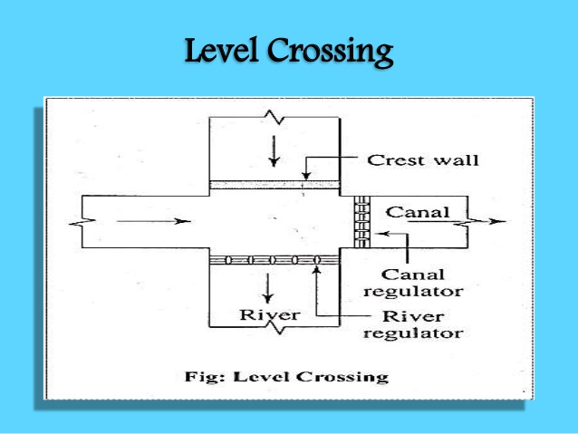
Level Crossing:
When the bed level of canal is equal to the drainage bed level, then level crossing is to be constructed. This consists of following steps:
- Construction of weir to stop drainage water behind it
- Construction of canal regulator across a canal
- Construction of head regulator across a Drainage
Functioning of a level crossing:
In peak supply time of canal water parallel to drainage, both the regulators are opened to clear the drainage water from that of canal for certain time interval. Once the drainage is cleared, the head regulator is closed down. Anyhow, cross regulator is always in open condition throughout year to supply canal water continuously.
Canal inlets:
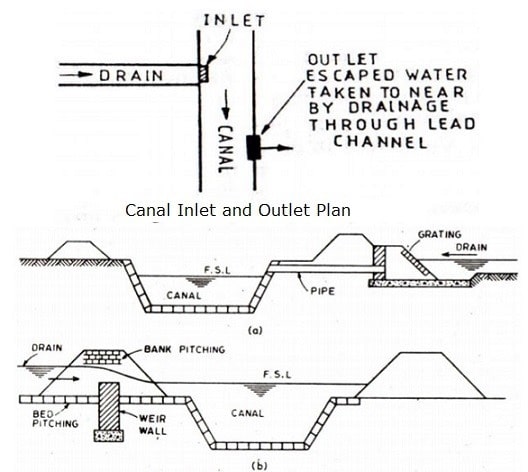
In a canal inlet structure, the drainage water to be admitted into canal is very less. The drainage is taken through the banks of a canal at inlet. And then this drainage mixed with canal travels certain length of the canal, after which an outlet is provided to create suction pressure and suck all the drainage solids, disposing it to the watershed area nearby.
There are many disadvantages in use of canal inlet structure, because the drainage may pollute canal water and also the bank erosion may take place causing the canal structure deteriorate so that maintenance costs are high. Hence this type of structure is rarely constructed.
The following factors should be considered while selecting the most suitable type of the cross-drainage work-
A- Relative levels and discharges-
The relative levels and discharges of the canal and of the drainage mainly affect type of cross-drainage work required. The following are the broad outlines:
- If the canal bed level is sufficiently above the H.F.L. Of the drainage, an aqueduct is selected.
- If the F.S.L. Of the canal is sufficiently below the bed level of the drainage, a super-passage is provided.
- If the canal bed level is only slightly below the H.F.L. Of the drainage, and the drainage is small, a siphon aqueduct is provided. If necessary, the drainage bed is depressed below the canal.
- If the F.S.L. Of the canal is slightly above the bed level of the drainage and the canal is of small size, a canal syphon is provided.
- If the canal bed and the drainage bed are almost at the same level, a level crossing is provided when the discharge in the drainage is large, and an inlet-outlet structure is provided when the discharge in the drainage is small. However, the relative levels of the canal and the drainage can be altered to some extent by changing the canal alignment to have another crossing. In that case, the most suitable type of the cross-drainage work will be selected depending upon the levels at the changed crossing.
B- Performance-
As far as possible, the structure having an open channel flow should be preferred to the structure having a pipe flow. Therefore, an aqueduct should be preferred to a syphon aqueduct. Likewise, a super-passage should be preferred to a canal siphon. In the case of a syphon aqueduct and a canal syphon, silting problems usually occur at the crossing. Moreover, in the case of a canal syphon, there is considerable loss of command due to loss of head in the canal. The performance of inlet-outlet structures is not good and should be avoided.
C- Povision of road-
An aqueduct is better than a super-passage because in the former, a road bridge can easily be provided along with the canal trough at a small extra cost, whereas in the latter, a separate road bridge is required.
D- Size of the drainage-
When the drainage is of small size, a syphon aqueduct will be preferred to an aqueduct as the latter involves high banks and long approaches. However, if the drainage is of large size, an aqueduct is preferred.
E-Materials of construction-
Suitable types of material of construction in sufficient quantity should be available near the site for the type of cross-drainage work selected. Moreover, the soil in sufficient quantity should be available for constructing the canal banks if the structure requires long and high canal banks.
F-Cost of construction-
The cost of construction of cross-drainage work should not be excessive. The overall cost of the canal banks and the cross-drainage work, including maintenance cost, should be a minimum.
G-canal alignment-
The canal alignment is sometimes changed to achieve a better type of cross-drainage work. By changing the alignment, the type of cross-drainage can be altered. The canal alignment is generally finalized after fixing the sites of the major cross-drainage works.
H-Permissible loss of head-
Sometimes, the type of cross-drainage is selected considering the permissible loss of head. For example, if the head loss cannot be permitted in a canal at the site of cross-drainage, a canal syphon is ruled out.
The following steps may be involved in the design of an aqueduct or a syphon-aqueduct-
Step1-determination of maximum flood discharge-
The high flood discharge for smaller drains may be worked out by using empirical formulas ; and for large drains, other reliable methods such as Hydrograph analysis, Rational formula, etc. may be used.
Step2-fixing the waterways requirements for aqueduct & siphon aqueduct-
An approximate value of required waterway for the drain may be obtained by using the Lacey's equation, given by
P= 4.75 √Q
Step3- afflux and head loss through siphon barrels-
It was stated earlier that the velocity through syphon barrels is limited to a scouring value of about 2 to 3 m/sec. A higher velocity may cause quick abrasion of the barrel surfaces by rolling grit, etc. and shall definitely result in higher amount of afflux on the upstream side of the syphon or syphon-aqueduct, and thus, requiring higher and longer marginal banks.
The head loss (h) through syphon barrels and the velocity (V) through them are generally related by Unwin's formula*, given as :
h = [1 + f 1 + f2*L/R+⌡V2/2g-Va2/2g
Step4- fluming of the canal-
The contraction in the waterway of the canal (i.e. · fluming of the canal) will reduce the length of barrels or the width of the aqueduct. This is likely to produce economy in many cases. The fluming of the canal is generally not done when the canal section is in earthen banks. Hence, the canal is generally riot flumed in works of Type I and Type II. However, fluming is generally done in all the works of Type III.
Step5- design of pucca canal trough-
In case of an aqueduct syphon, besides the vertical load of canal water, one more force comes into action i.e. the uplift pressure exerted by the drain water. The roof of the culvert i.e. the bottom-slab of ca.nal should now be designed . To withstand these two forces independently. Although these two forces act in a opposition to each other but still under the worst circumstances, there may-be times when only on of them may be acting.
Step6- design of bottom floor for an aqueduct and siphon aqueduct
Step7- design of bank contraction-two sets of wings are required in aqueduct & siphon aqueduct-
1- Canal wings
2- Drainage wings
Introduction-
The river flowing in alluvial plains meander in wide widths. River discharge also vary widely. When a barrage is constructed across a river,the river is made to forced or guided to flow through it. More ever fluming of waterways ,barrages results in afflux which may sometimes be several feet.
Therefore to insure that the river flows through the barrage and protect the submerging of large tracts of costly land and property upstream , certain works upstream of barrage are constructed. These works are called river training works.
'River training' refers to the structural measures which are taken to improve a river and its banks. River training is an important component in the prevention and mitigation of flash floods and general flood control, as well as in other activities such as ensuring safe passage of a flood under a bridge .
1-on the basis of topography-
- River in hills(upper reaches)
- River in alluvial plains(lower reaches)
River in hills- these rivers takes off from the mountains flow through hilly region , finally entering into the plains. These are classified as-
- Rocky river
- Boulder river
In rocky river the flow channel is generally formed by the process of degradation.
In boulder river ,the river bed contains of a mixture of boulder, gravel,shingle ,created by the soils.
River in alluvial plains- they are various types-
- Aggrading
- Degrading
- Stable river
- Deltaic
Aggrading river- it is a silting river in which increase in bed slope.
Degrading river- if the river bed is constantly getting scoured to reduce and dissipate excess available slope then the river is known as degrading river.
Stable river- when the slope ,regime, alignment does not change significantly it is known as stable river.
Deltaic river- A river before it joins the sea , gets divided into branches . Thus a shape of delta is formed is called deltaic river.
2-on the basis of source-
1- Flashy river
2- Virgin river
Flashy river-if rise and fall in a river is sudden then it is called flashy river.
Virgin river- in arid region a river ,may completely dry before it gains another river in the oceans .such type of river is called virgin river.
3- on the basis of regime conditions in india-
1- Himalayan rivers
2- Non Himalayan rivers
Himalayan rivers-the river takes off from Himalayas and flow through alluvial plains. These rivers are perennial.Ex- Indus, Jhelum,Chenab, ravi, beas,Sutlej, ganga, kosi etc.
Non Himalayan rivers- these are non perennial rivers. They receive their water supply only in rainy seasons. Ex-chambal, Mahanadi, godawari, tapti, narmada etc.
Behaviour Of Rivers-
We shall now discuss the behaviour of the rivers in special situations,such as in bends, meanders and cutoffs, in details.
Straight Reaches. In a straight reach of a river, the river cross-section is in the shape of a trough, with high velocity flow in the middle of the section.
Bends. Every alluvial river tends to develop bends, which are characterized by scouring on the concave side and silting on
The convex side.
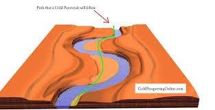
Meanders. When once a river deviates from its axial path and a curvature is developed (either due to its own characteristics or due to the impressed external forces), the process moves
Downstream by building up shoals on the convex side by means
Of secondary currents. The formation of shoals on the convex side, results in further shifting of the outer bank by erosion on the concave side.
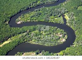
Cutoff- In a meandering river a particular bend may sometimes be abandoned by formation of straighter and shorter channel. The process whereby this chord channel developed is called cut off. The cut off reduces the river length.
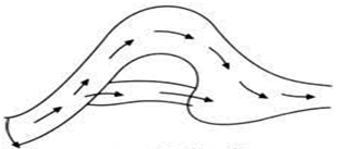
- To provide and non-tortuous approach to weir.
- To prevent the river from out-flanking the weir.
- To prevent additional area to be submerged due to afflux.
- To prevent erosion of the river banks (protective works).
- To ensure smooth and axial flow of water, to prevent the river from out ------ the works due to change in its course.
- Stability of river banks is achieved by training methods, such as stone pitching or lining of banks.
They are 3 types-
1- High water training (training for discharge)
2- Low water training(training for depth)
3- Mean water training (training for sediment)
High water training or Training for discharge- High water training is under· taken with the primary purpose of flood control. It, therefore, aims at providing sufficient river cross-section for the safe passage of maximum flood, and Is concerned with making the adjoining area flood-proof, by construction of dykes or levees, etc.
Low water training or Training for depth- Low water training is undertaken with the primary purpose of providing sufficient water depth in navigable channels during low water 'periods. It may be accomplished, by concentrating and enhancing the
Flow in the desired channel by closing other channels, by the process of bandalling by contracting the width of the channel with the help of 'groynes ', etc.
Mean water training or Training for sediment-Mean water training aims at efficient disposal of suspended load and bed load, and thus, to preserve .the channel in good shape. The maximum accretion capacity of a river occurs in the vicinity of mean' water or dominant discharge. Therefore, the changes in the river bed are attempted in accordance with that stage of flood flow. The mean water training is the most important type and forms the basis on which the former two are planned.
PURPOSE OF RIVER TRAINING WORKS- it has following purpose-
1- Protection of bed and banks of river from erosion.
2- Directing the river flow in desired direction.
3- Maintenance of river channel for navigation.
4- Protection of surrounding land from flooding.
5- Protection of important hydraulic structures.
6- To prevent the river from changing its course. When a river changes its course surrounding valuable property falls in the river course. Thus, the useful land is turned useless.
Some of the river training structures are discussed here-
- Marginal embankments or levee
- Guide banks
- Groynes
- Artificial cut offs
- Pitched islands
- Miscellaneous methods such as sill
1-Marginal Embankment of levee-
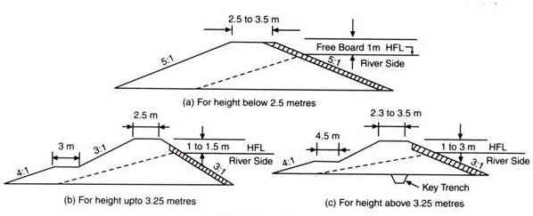
The floods may be prevented from submerging the country by constructing earth embankments. They are generally constructed up to a height of 12 m. They are designed and constructed in the same way as an earth dam. The embankments are generally constructed parallel to the river channel.
The marginal embankments are constructed as close to the banks as possible to restrict the flood water from submerging the area behind them. Figure shows the position of marginal embankments.

They are designed to hold up the water up to a maximum anticipated HFL without the possibility of overtopping and with a view to withstand all external pressures. This condition is met with by providing sufficient freeboard, bed width, top width and stone protection on adequate slopes.
Advantages-
(i) They are very widely used river training work.
(ii) It is cheaper and quick as well as simple in construction. They can be constructed with locally available material.
(iii) Maintenance of embankments is similar to canal bank maintenance and does not involve intricate methods.
(iv) Embankment can be constructed reach by reach to extend extent of protection.
(v) They protect large areas by comparatively small investment.
Rivers in flood plains submerge very large areas during flood periods. Naturally when some structure is to be constructed across such a river (for example, bridge, weir, etc.), it is very expensive to construct the work spanning whole width of the river. To economies some training work may be constructed to confine the flow of water within a reasonable waterway.
Guide banks are meant for guiding and confining the flow in a reasonable waterway at the site of the structure. The design of the guide banks is based on the theory developed by Mr. Bells. Hence, guide banks are also known as Bell’s bunds. This river training work has been devised from a study of the natural river channel in alluvial reach.
The river has a tendency to meander over large width of low lying land thereby flooding it occasionally. But it was observed that the same stream passes through narrow and deep sections where high and stiff permanent banks are available on either side without appreciable afflux or abnormal velocity.
The guide banks guide the river flow past a bridge or any other hydraulic structure without causing damage to the work and its approaches. The guide banks are constructed parallel or approximately parallel to the direction of flow. They extend both upstream and downstream of the abutments of the hydraulic structure. The guide banks may be provided on either side of the hydraulic structure or on one side as required.
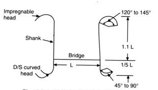
The guide banks consist of four parts mainly:
i. Upstream curved head or impregnable head,
Ii. Downstream curved head,
Iii. Shank or a straight portion which joins the two curved heads, and
Iv. Slope and bed protection, it includes apron.
Selection of Site and Section of Guide Banks:
The site for guide banks should be selected in such a way that there is no side channel flowing parallel to the guide banks. The side channel if present may breach the approach embankment. The guide banks should be so designed that no swirls are produced.
The top width of bank should not be less than 3 m. Side slopes should be 2:1 and free board 1.25 to 1.50 meters. While providing the free board due weightage should be given for heading up of the water and also for settlement of banks (generally 10 per cent of height). The inside slope should be protected with stone pitching and outside slope with good earth.
The waterway is given by Lacey’s regime perimeter formula:
Pw = 4.825 Q1/2
Where Pw is waterway in metres and
Q is discharge in cubic metres/sec. The length of upstream part of the guide bank should be 10 per cent more than the length of a bridge or any other structure between the abutments. The length of downstream part of the guide bank should be 1/5 of the structure.
They are the structures constructed transverse to the river flow. They extend from the bank into the river.
Groynes serve following purposes:
a. They protect the river bank by keeping the flow away from it.
b. They create still pond along a particular bank with the aim of silting up the area in the vicinity.
c. They train the river to flow along a desired course by attracting, deflecting or repelling the flow.
d. They contract the wide river channel for improving the navigation depth.
Classification of Groynes:
Various classifications of spurs or groynes may be given as mentioned below:
1. Classification according to the method of construction.
(a) Permeable, and
(b) Impermeable.
2. Classification according to the height of the spur below high water.
(a) Submersible, and
(b) Non-submersible.
3. Classification according to the functions served.
(a) Attracting type,
(b) Deflecting type,
(c) Repelling type, and
(d) Sedimenting type.
Impermeable Groynes:
The groynes may be aligned either perpendicular to the bank or inclined, pointing upstream or downstream. When a groyne points upstream then it is called a repelling groyne. The reason being, this type has a property of repelling the river flow away from the bank (Fig 14.8) .This is accomplished by creation of a still pond on the upstream. Obviously the river starts following beyond the still pond and in the process the river flow goes away from the bank.
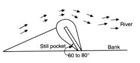
On the contrary, when a groyne points downstream it is called an attracting groyne as. It attracts the river flow towards the bank from which it takes off (Fig. 14.9).
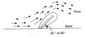
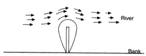
In this case the groyne actually provides a body against which the river current keeps hugging. The river flow thus remains along the bank permanently. When a groyne of short length is taken perpendicular to the bank, it only deflects the flow locally. Hence, it is called deflecting groyne
.
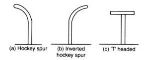
After successfully conducting model experiments various designs for groyne heads have been evolved. A groyne with head normal to the groyne direction of called ‘T’ headed groyne
6.14-Artificial Cut Offs
Sometimes alluvial river flowing along curves or bends abandons a particular bend and establishes its main flow along a comparatively straight and short channel which is called cutoff.
At times, it is advantageous to make an artificial cutoff by excavating a pilot channel of small cross-section and letting it develop by itself in due course of time so that the river in that region abandons the curved path and adopts the new course along the artificial cutoff.
Artificial cutoff avoids the chaotic or non-equilibrium conditions which prevail during occurrence of natural cutoff. Artificial cutoffs shorten the travel distance, and increase ease of maneuvering of a navigating vessel. Artificial cutoff also diverts the river from a curved path which might be endangering important land area.
Development of Cut-Off:
Cut-off develops due to following reasons:
i. Development of Bars at Infliction:
The flow through the main channel is reduced because of the growth of bars at inflections. This induces flow through already existing shallow side channels. Discharge is main channel being reduced continues to silt and more and more discharge gets diverted to the side channel which ultimately leads to the formation of cut-off.
Ii. Formation of Drops at the Junction of Main Channel with Side Channel.
The side channel usually has a smaller velocity and smaller length with the same head difference as the channel. It, therefore, joins the main channel at a local drop. This local drop cuts back into the side channel and tends the development of a cut-off.
Iii. Steep Slope and Unfavourable Cross-Section:
The steep slope of the side channel along with unfavourable cross-section generate such velocities which cause erosion of the bed and bank of the side channel.
Iv. Bend Erosion:
Erosion of the concave banks increase the curvature of the river. The erosion might occur to such an extent that the arms of a loop cut into one another and cut-off occurs.
v. Duration of Flood:
The duration of flood should be sufficient so that stream may erode its bed and banks
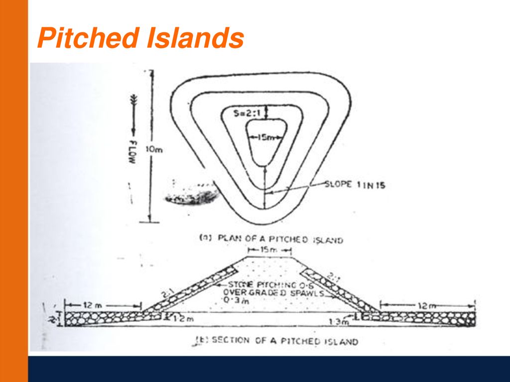
A 'pitched island' is an artificially constructed island in the river bed and is protected by stone pitching on all sides. Because of the turbulence generated by the island in its vicinity, the river channel around the island gets deepened and thus, attracting the river towards itself and holding it permanently. Pitched islands may therefore, help in attracting the current towards themselves and thus, reduce undue concentration on the opposite banks.
(i) Submerged Dikes (called Sills) are used as a river training measure in particular situations. Sometimes, a river may create deep channels in the vicinity of certain pucca structures and are required to be corrected. In such situations, sills are placed across the scoured portion of the bed, with their top levels at or slightly below the designed bed level aspired to be achieved after correcting the deep scours. They are spaced closely, so as to ensure their proper functioning.
(ii) Closing Dykes are sometimes used to close a particular flow, so that the river flow may be directed in some other desired direction.
Reference Books
- Design of Small Dams- United States Department of the Interior, Bureau of Reclamation revised reprint 1974, Oxford and IBH Publishing Co.
- Irrigation and Water Resources Engineering- Asawa G.L- New Age International (P) Ltd. Publishers, first ed, 2005.
- Engineering for Dams- CreagerW.P, Justin J.D, Hinds J -Wiley Eastern Pvt. Ltd., New Delhi, 1968
- Irrigation Engineering and Hydraulic Structures- Garg S.K- Khanna Publishers N.D. 13th ed, 1998.
- Hydraulic Structures, Vol. 1. & Vol. 2- Grishin M.M- Mir Publishers, Moscow, 1982.
- Design Textbook in Civil Engineering: Volume Six: Dams- Leliavsky, Serge – Oxford and IBH Publishing Co. Pvt. Ltd., 1981.
- Roller Compacted Concrete Dams- MehrotraV.K- Standard Publishers Distributors, Delhi, 1st ed, 2004. 8. Irrigation, Water Resources and Water Power Engineering- Modi, P.N. - Standard Book House, New Delhi, 2nd ed, 1990.
- Earth and Earth Rock Dams- Sherard J.L, Woodward R.J. - John Wiley and Sons, inc. 1963.