Unit 4
Laminar & Turbulent flow through pipes
Characteristic of Laminar Flow
Laminar is characterized by smooth streamlines and highly ordered motion. Under most practical conditions, the flow in a circular pipe is laminar for Re < 2000.
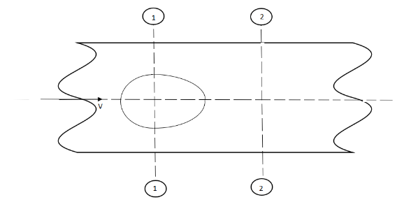
In fully developed laminar flow, each fluid particle moves at a constant axial velocity along a streamline and the velocity profile remains unchanged in the flow direction.
The steady laminar flow of an incompressible fluid with constant properties in the fully developed region of a straight circular pipe.
Laminar flow in a straight pipe may be considered as the relative motion of a set of concentric cylinders of fluid, the outside one fixed at the pipe wall and the others moving at increasing speeds as the center of the pipe is approached.
Smoke rising in a straight path from a cigarette is undergoing laminar flow. After rising a small distance, the smoke usually changes to turbulent flow, as it eddies and swirls from its regular path.
Examples
Laminar flow is common only in cases in which the flow channel is relatively small, the fluid is moving slowly, and its viscosity is relatively high.
Oil flow through a thin tube or blood flow through capillaries is laminar.
Most other Kinds of fluid flow are turbulent except near solid boundaries, where the flow is often laminar, especially in a thin layer just adjacent to the surface
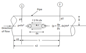
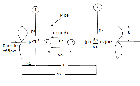
Fig: Shows a horizontal circular pipe of radius R, having the laminar flow of fluid through it.
Consider a small concentric cylinder of radius r and length dx as a free body.
If  is the shear stress, the shear force F is given by
F =  x 2
x 2  r x dx
Let P be the intensity of pressure at left end and the intensity of pressure at the right end be (
Thus, the force acting on the fluid element is:
i) the shear force,  x 2
x 2 r x dx on the surface of a fluid element.
ii) The pressure force, P x  on the left end.
iii) The pressure force, ( on the right end.
For steady flow, the net force on the cylinder must be zero.
 [ p x
[ p x  - (
- ( ] –
] – 
 -
-  -
-

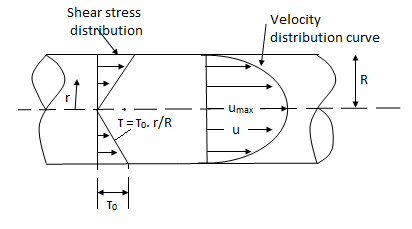
Shear stress is zero at the center of pipe (r = 0) and maximum at the pipe wall given by
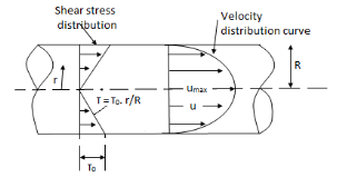
 (
( )
)
From Newton’s Law of viscosity.

In this equation, the distance y is measured from the boundary. The radial distance r is related to distance y by the relation.
y = R-r or dy = -dr

Comparing two values of 
 =
= 
 du =
du =  (
( )r.dr
)r.dr
Integrating the above equation w. r. t. ‘r’ we get
 u =
u =  .
.  r2 + C --------------- (ii)
Where C is the constant of integration and its value is obtained from the boundary conditions.
At r = R, u = 0
 0 =
0 =  .
.  R2 + Cor C =
  .
.  R2
R2
Substituting this value of C in eqn. (ii) we get,
 u =
u =  .
.  r2
r2 .
.  R2
R2
 u = -
u = -  .
.  (R2 – r2)
Shows that the velocity distribution curve is a parabola.
The maximum velocity occurs, at the center and is given by.
 umax = -
  R2
R2
The instantaneous velocity at the given point can be expressed as
u =  + u’
+ u’
u = instantaneous velocity
 = time average for temporal mean velocity and
u' = velocity fluctuation (fluctuating component)
Similarly, v =  +v’
+v’
w =  + w’
+ w’
And p = + p’
+ p’
From the definition of average velocity is we have,


where T = large interval of time.
The magnitude of Turbulence = Arithmetic means of root means the square value of turbulent fluctuations in the three directions.

Intensity of turbulence

Where  = Line average resultant velocity at that point.
Instantaneous Velocity:
Temporal Mean Velocity:

Scale of turbulence


Intensity of turbulence

Where  &
& are the fluctuations of the velocity vector components
 = Line average resultant velocity at that point.
According to Prandtl, the mixing length (l) is defined as the average lateral distance through which a small mass of fluid particles would move from one layer to the other adjacent layers before acquiring the velocity of the new layer.
He assumed that components u' and v' are of the same order and the velocity fluctuation in the x-direction is related to the mixing length as


When the viscous action is also included, the total shear stress may be expressed as

Above equation is used for most of the turbulent flow problems for determining the shear stress.
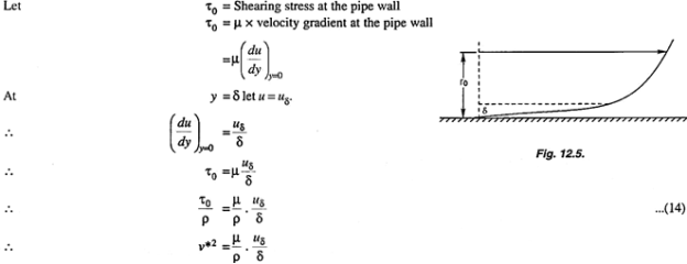
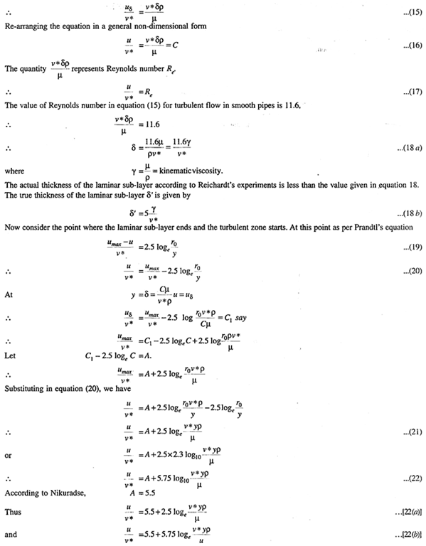
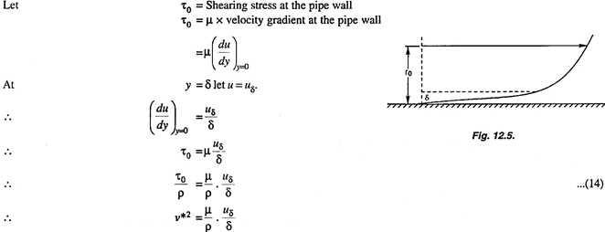
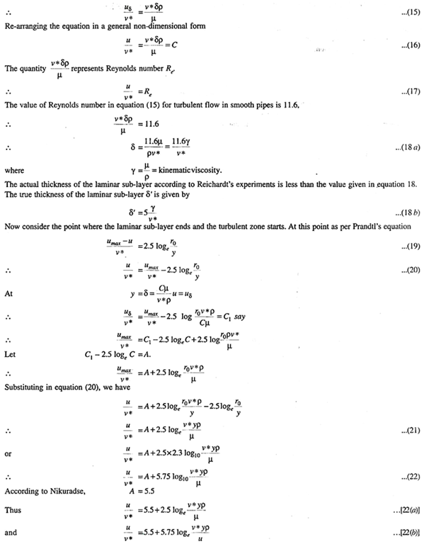
Prandtl’s universal velocity distribution equation is valid in the central region of the pipe where the turbulent flow is fully developed. But in the regions close to the pipe wall the flow is not fully turbulent, and is more close to laminar flow. There exists a distance  from the surface of the wall up to which the velocity varies linearly as shown in fig.
This thickness is the thickness of the laminar sub-layer and is very small compared with the pipe radius r0.
2. Velocity Distribution for Turbulent Flow in Rough Pipes
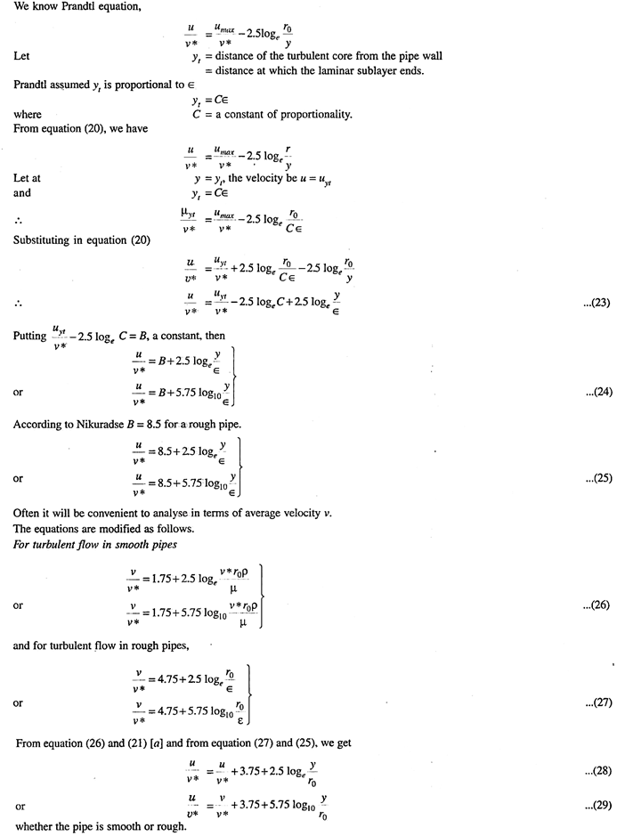
The roughness of the pipe wall is due to the undulation of the surface or uneven projection of the surface. Let ϵ be the average height of protuberance (projection), and r0 the radius of the pipe. If ϵ > laminar sublayer the pipe is considered as a rough pipe. The distribution of velocity in this case can be derived as follows.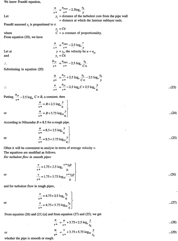
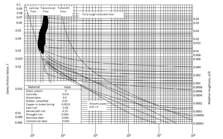
Variation of friction factor f for laminar flow
The friction of factor f for laminar flow in pipes is given by

The equation shows that for laminar flow the friction factor f varies inversely with Re and it is independent of K/D ratio.
Variation of friction factor f for turbulent flow
For the fully developed turbulent flow, the friction factor f is a function of Re or K/D ratio or both, depending on whether the boundary is hydrodynamically smooth or rough or it is in transition.


where D = Diameter of the pipe
 = Density of the fluid.
 = Dynamic viscosity of the fluid.
K= average height of pipe wall roughness protrusions.
The term K / D is commonly known as relative roughness.
The equation 1 general equation applies to laminar as well as the turbulent flow in pipes.
Variation of friction coefficient f for smooth pipe-


Nikuradse’s experimental result for turbulent flow in smooth pipeFor Re = 5×10⁴ to Re as high as 4 × 10⁷ for f is

f = 
Variation of friction coefficient f for rough pipes


where f1 (friction factor) = 4f (friction coefficient)


When water flows in a pipe, it experiences some resistance to its motion, due to which its velocity and ultimately the head of water available is reduced.
Major energy losses
This loss is due to friction.
Darcy – Weisbach formula
The loss of head in pipes due to friction is calculated from Darcy-Weisbach formula which is given by

where, hf = loss of head due to friction,
f = co-efficient of friction,(a function of Reynolds number, Re)
f =  for Re varying from 4000 to 106
=  for Re < 2000 (laminar/ viscous flow)
L = Lengthof the pipe
V = Mean velocity of flow, and
D = Diameter of the pipe.
Minor Energy Loses
The minor loss of energy (or head) includes the following cases :
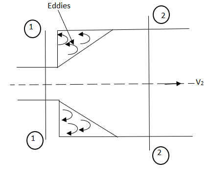
- Consider a liquid flowing through a pipe that has sudden enlargement as shown in fig.
- =


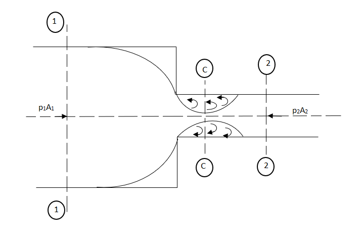
- Consider a liquid flowing in a pipe that has a Sudden Contraction in the area as shown in fig.
- =
 [
[ ]2
]2
- This is the loss of energy which occurs when a liquid enters a pipe that is connected to a large tank or reservoir.

- This is the loss of head due to the velocity of the liquid at the outlet of the pipe which is dissipated either in the form of a free jet or it is lost in the tank or reservoir.

- Whenever there is an obstruction in a pipe, the loss of energy takes place due to the reduction of the area of the cross-section of the pipe at the place where the obstruction is present.
a = Maximum area of obstruction
A = Area of pipe
V = Velocity of liquid in the pipe
 [
[  ]2
]2
- When there is any bend in a pipe, the velocity of the flow changes, due to which the separation of the flow from the boundary and also the formation of eddies takes place.


- The loss of head in various pipe fittings such as valves, couplings, etc. is expressed as


The basic approach to all piping systems is to write the Bernoulli equation between two points, connected by a streamline, where the conditions are known. For example, between the surface of a reservoir and a pipe outlet.
Equation for major losses in pipe
Major loss in pipe flow is because of Friction.
Friction losses are a complex function of the system geometry, the fluid properties and the flow rate in the system. By observation, the head loss is roughly proportional to the square of the flow rate in most engineering flows (fully developed, turbulent pipe flow). This observation leads to the Darcy-Weisbach equation for head loss due to friction:
Equation for minor losses in pipe
The minor losses are any head loss present in addition to the head loss for the same length of straight pipe.
Like pipe friction, these losses are roughly proportional to the square of the flow rate. Defining K, the loss coefficient, by

allows for easy integration of minor losses into the Darcy-Weisbach equation. K is the sum of all of the loss coefficients in the length of pipe, each contributing to the overall head loss.
Although K appears to be a constant coefficient, it varies with different flow conditions. Factors affecting the value of K include:
To calculate losses in piping systems with both pipe friction and minor losses use
in place of the Darcy-Weisbach equation. The procedures are the same except that the K values may also change as iteration progresses.
Pipes in series
L1, L2,L3 = Length of pipes 1, 2 and 3 respectively
d1, d2, d3 = diameters of pipes 1, 2, 3 respectively
v1, v2, v3 = velocity of flow through pipes 1, 2, 3
f1, f2, f3 = coefficients of frictions for pipes 1, 2, 3
H = difference of water level in the two tanks
The discharge passing through each pipe is the same


The difference in liquid surface levels is equal to the sum of the total head loss in the pipes.

If minor losses are neglected, then the above equation becomes as

Pipe in parallel

In this arrangement, the loss of head for each branch pipe is the same.
Hence, Loss of head for branch pipe 1 = Loss of head of the branch pipe 2

Equivalent pipe
L1= length of pipe 1 and d1 = diameter of pipe 1
L2 = length of pipe 2 and d2 = diameter of pipe 2
L3 = length of pipe 3 and d3 = diameter of pipe 3
H = total head loss
L = length of equivalent pipe
d = diameter of equivalent pipe
Total head loss in the compound pipe, neglecting minor losses
 --------- 1
f1 = f2 = f3 = f


Substituting these values in equation 1, we have

 --------- 2
Head loss in the equivalent pipe, 
Where 
 --------- 3
Head loss in the compound pipe and the equivalent pipe is same hence equating equations 2 and 3, we have

or 
 --------- 4
Equation 4 is known as the Dupuit equation
This method is applicable to closed-loop pipe networks. The outflows from the system are assumed to occur at the nodes, where a node is the end of each pipe. This assumption would therefore result uniform flow in the pipelines distribution systems.
The Hardy-Cross analysis is based on the principles that

2. Head balance criterion: algebraic sum of the head losses around any closed-loop is zero.

For a given pipe system, with known junction outflows, the Hardy-Cross method is an iterative procedure based on initially estimated flows in pipes. Estimated pipe flows are corrected with iteration until head losses in the clockwise direction and in the anticlockwise direction are equal within each loop.
2. With the assumed value of Q, the head loss in each pipe is calculated according to the equation

Where
 : Head loss
r: head loss per unit flow
n: flow exponent
3. The net head loss around each loop is calculated.
4. If the net head loss due to assumed values of Q round the loop is zero, then the assumed values of Q in that loop are correct. If this is not the case, then the assumed values of Q are corrected by including a correction ï„Q for the flows till the circuit is balanced.
5. The correction factor ï„Q is obtained by

6. For turbulent flow, the value of n=2 and hence the correction factor becomes

7. If the value of ï„Q is positive, then it is added to the flow in the clockwise direction and subtracted from the flows in the anticlockwise direction.
8. After the corrections have been applied to each pipe in a loop and to all loops, a second trial calculation is made for all loops. This procedure is repeated till ï„Q becomes negligible.

Reference books:
1. Engineering Fluid Mechanics by R. J. Garde and A.J Mirajgaonkar, Pub: SCITECH Publications( India )Pvt. Ltd, Chennai
2. Fluid Mechanics and its Applications, Vijay Gupta, Santosh K Gupta, New Age International Pvt. Ltd, New Delhi,
3. Fluid Mechanics, Fundamentals, and applications by Yunus. A Cengel and John. M Cimbala, Mc Graw Hill International, New Delhi.
4. Fluid Mechanics by Streeter, Wylie, and Bedford – Pub: McGraw Hill International, New Delhi.
5. Open Channel Hydraulics by Ven Tee Chow, Pub: Mcgraw- Hill Book Company- Koga.
6. A Text-Book of Fluid Mechanics and Hydraulic Machines- by Dr. R K Rajput Pub: S Chand and Co Ltd. New Delhi