Unit 6
GVF in Open Channel Flow & Fluid flow around Submerged Objects
Introduction
The flow in an open-channel is termed as gradually varied flow (GVF) when the depth of flow varies gradually with longitudinal distance. Such flows are encountered both on upstream and downstream sides of control sections.
Analysis and computation of gradually varied flow profiles in open-channels are important from the point of view of safe and optimal design and operation of any hydraulic structure.
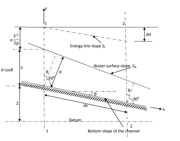
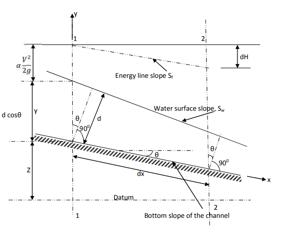
In the above figure, H = total energy (or head); E = specific energy; Z = vertical distance of the channel bottom above the datum in meters; d = depth of flow section normal to the bed in meters; θ = channel bottom slope angle; α = kinetic energy correction factor; V = mean velocity of flow through the section in m/s.
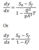
The dynamic equation for GVF for small bed slopes-
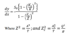
In terms of section factor the dynamic equation can be written as-
Z is the section factor at depth y and Zc is the corresponding section factor at critical
depth Yc. This equation is commonly used with direct integration technique.
In terms of Energy equation, the dynamic equation can be written as-
This is called the differential energy equation of gradually varied flow. This equation is very useful in developing numerical techniques for the gradually varied flow profile computation.
Classification of channel bed slopes
For a given channel with a known Q = Discharge, n = Manning coefficient, and S0 =Channel bed slope, yc = critical water depth and y0 = Uniform flow depth can be computed. There are three possible relations between y0 and yc as 1) y0 > yc , 2) y0 < yc ,3) y0 = yc .
For horizontal (S0 = 0), and adverse slope ( S0 < 0) channels,
Horizontal channel, S0 = 0→ Q = 0,
Adverse channel , S0 < 0 , Q cannot be computed,
For horizontal and adverse slope channels, uniform flow depth y0 does not exist.
Based on the information given above, the channels are classified into five categories as
indicated in Table

Various GVF profiles
The surface curves of water are called flow profiles (or water surface profiles).
Depending upon the zone and the slope of the bed, the water profiles are classified into 13 types as follows:
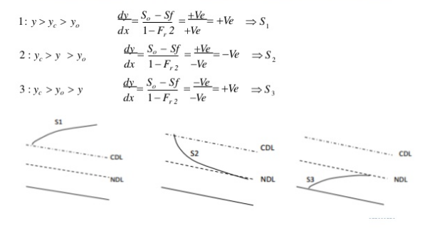
In all this curves, the letter indicates the slope type and the subscript indicates the zone.For Ex. S2 curve occurs in the zone 2 of the steep slope.
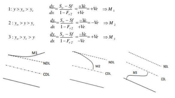
-Classification of Surface Profiles
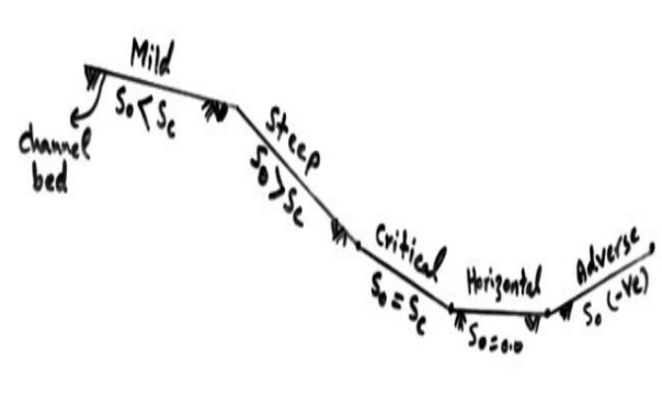
1) Mild slope (M)
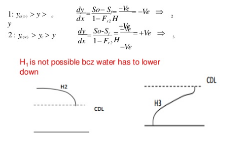
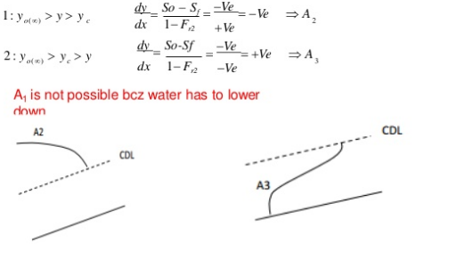
Y0 > Yc Type 1: If the stream surface lies above both
the normal and critrical depth of flow
(M1,S1)
S0 < Sc
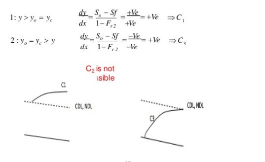
2)Critical slope (C)
Y0 = Yc Type 2: If the stream surface lies between
the normal and critrical depth of flow
(M2,S2)
S0= Sc
3)Steep slope (S)
Y0 < Yc Type 3: If the stream surface lies below both
the normal and critrical depth of flow
(M3,S3)
S0 > Sc
3)Horizontal slope (H)
S0= 0
4)Adverse slope (A)
S0= -ve

B. Steep Slope (S)
C. Critical Slope (C)
D. Horizontal Slope (H)
E.Adverse Slope (A)
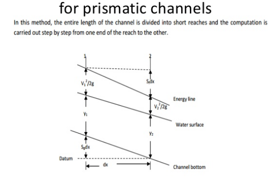
6.4 Methods of GVF computations:
1) Grphical Integration method
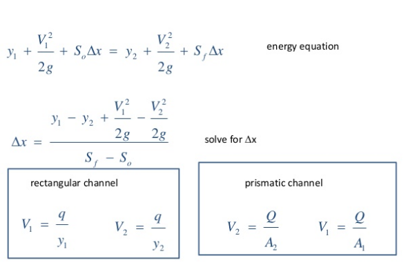
2) Direct step method
3) Standard step method
Direct step method
6.5 Fluid Flow around Submerged Objects:
When a body is placed in a moving fluid, a force is exerted on the body by the moving fluid. Similarly when a body moves within a fluid at rest then also a force is exerted on the body by the fluid. Motion of submarines, torpedos and aeroplanes are examples of this kind.
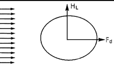
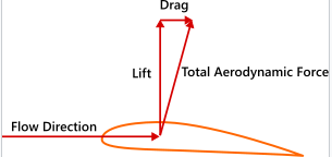
Consider a body placed in a fluid which is moving at a velocity U. The moving fluid will exert a force F on the body which can be resolved into two components namely the drag force exert a Fd in the direction of motion and the lift force FL normal to the direction of motion.
When the fluid is in motion the drag force acts on the body tending to move the body or drag the body in the direction of motion of the fluid. On the contrary when the body moves in the fluid, the drag force acts as a resistance to the motion of the body.
Definition of drag and lift:
Expressions for drag and lift :
Pressure force equal to ‘p dA ‘normal to area dA
Shear force equal  dA along the tangent to dA
dFD = Drag force on the element
=Component of ‘ p dA' in the horizontal direction
+Component of  dA ‘in horizontal direction
=p. dA cos  +
+
 dA sin
FD= FD =
FD =  dA.cos
 +
+  dA. Sin


in case of a flat plate held parallel to the stream = 90", cos
 = 0, sin
  =1 and hence
FD = only friction drag


hence
FD = only pressure drag.
= -p.dA.sin +
+ . dA. cos
FL =  dA.sin
 +
+  dA. Cos
Drag force : FD =CD x A x
Lift force : FL =CL x A x
FR = +
+
Coefficient of drag:
=pdA cos  +
+  dA cos (90° -
 )
)
= pdA cos +
+ dA sin


= cos
cos  dA +
dA +  sin
sin  dA.
dA.


FD =CD x A x
CD=Coefficient of drag
Coefficient of lift :
=-pdA sin  +
+  dA sin (90° -
 )
)
=- pdA sin +
+ dA cos
FL = dA cos
  +
+  dA sin
  .
.
FL =CL x A x
FL=Coefficient of lift
Type of drag:
1.Skin friction drag
2.Pressure drag
3.Profile drag
4.Deformation drag
5.Wave drag
6.Induced drag.
1.Skin Friction Drag :
2.Pressure Drag:

3.Profile Drag or Total Drag:
4.Deformation Drag:
5.Wave Drag :
6.Induced Drag :
Drag on a sphere:
Let U = Velocity of the flow of fluid over the sphere,
D = Diameter of the sphere.
p = Mass density of the fluid, and
H = Viscosity of fluid.
FD =3
Thus, Skin friction drag, F =
= FD =
FD =
 3
3 = 2
= 2
pressure drag, F =
= FD =
FD =
 3
3 =
= 
(i) Expression of Cd, for Sphere, when Reynolds Number is less than 0.2:
FD =CD x A x
FD =3


3 CD x
CD x 

= =
= 
The equation is called 'Stoke's law'.
(ii) Value of CD, for Sphere when Re, is between 0.2 and 5:
CD = 

 ]
]
is called Oseen formulae and is valid for R, between 0.2 and 5.
(iii) Value of CD for Re, from 5.0 to 1000:The drag co-efficient for the Reynolds number from to 1000 is equal to 0.4.
(iv) Value of CD for Re, from 1000 to 100,000: In this range, Cp is independent of the Reynolds number and its value is approximately equal to 0.5.
(iv) Value of CD for Re, more than  : The value of C, in approximately equal to 0.2 for Reynolds number more than
  .
.
Drag on a cylinder:
1. When Reynolds number (Re)< 1, the drag force is directly proportional to velocity and hence the drag coefficient (CD) is inversely proportional to Reynolds number.
2. With the increase of the Reynolds number from 1 to 2000, the drag coefficient decreases and reaches a minimum value of 0.95 at Re = 2000.
3.With the further increase of the Reynolds number from 2000 to 3 x  , the coefficient of drag increases and attains maximum value of 1.2 at Re = 3 x
  .
.
4. The value of the coefficient of drag decreases if the Reynolds number is increased from 3 x  to 3 x
  At Re = 3 x
  ,the value of CD = 0.3
5.If the Reynolds number is increased beyond 3 x , the value of CD increases and it becomes equal to 0.7 in the end.
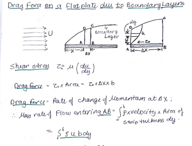
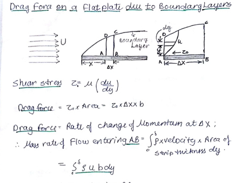
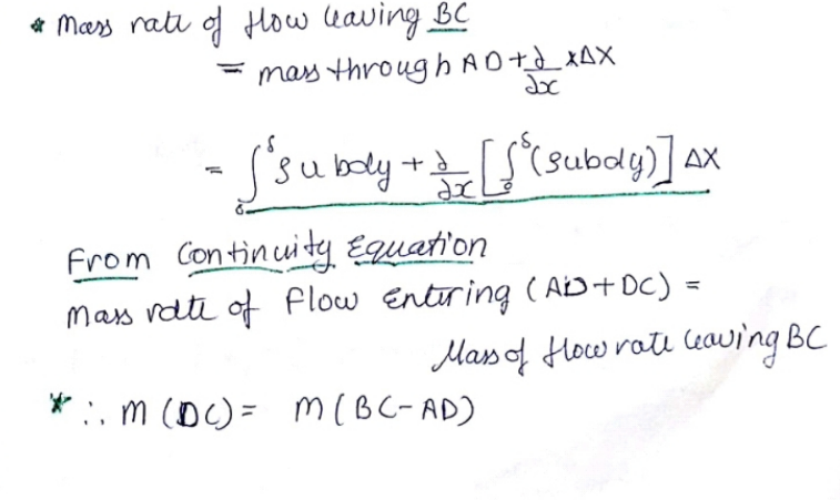
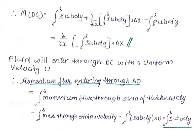
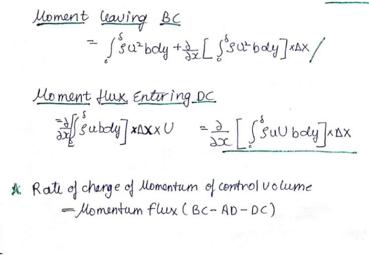
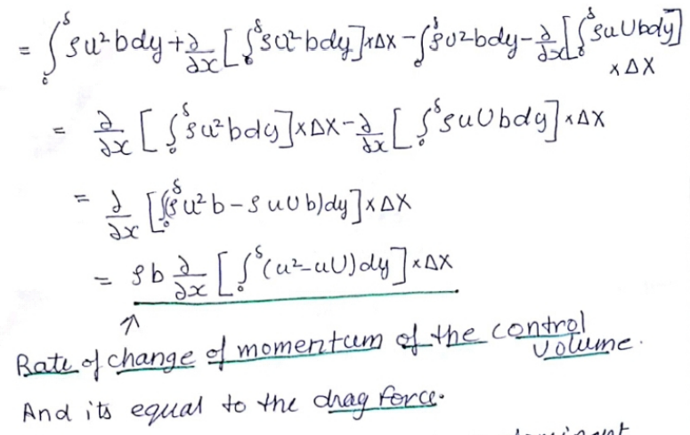
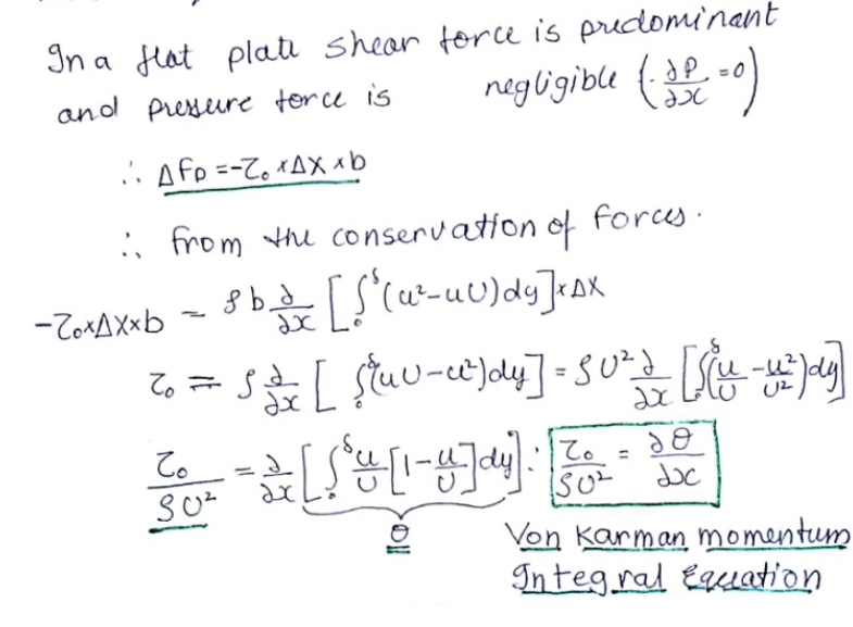
Drag on a flat plate:
Drag on aerofoil:
The drag force acting on a body in fluid flow can be calculated
FD = cD 1/2 ρ v2 A
where
FD = drag force (N)
cD = drag coefficient
ρ = density of fluid (kg/m3)
v = flow velocity (m/s)
A = body area (m2)
Required Thrust Power to overcome Drag Force
The thrust power required to overcome the drag force can be calculated
P = FD v (3)
where
P = power (W)

(i)Symmetrical configuration which is not stable at all and
(ii) Staggered configuration

Ut = = circulation around the vortex
f = 0.198  [1-
[1- ]
]
f  = 0.198 [1-
 ]
]

Lift on an aerofoil:
Chord Length 'C': It is the length of the line joining the leading edge and the trailing edge.
Span 'L': It is the length of the aerofoil, normal to the cross-section.
The angle of Attack (a): It is the angle made by the incoming flow with the underside of the aerofoil or with the chord length of the aerofoil.
Aspect Ratio 'AR': It is the ratio of span to the chord length of the aerofoil.
AR = 
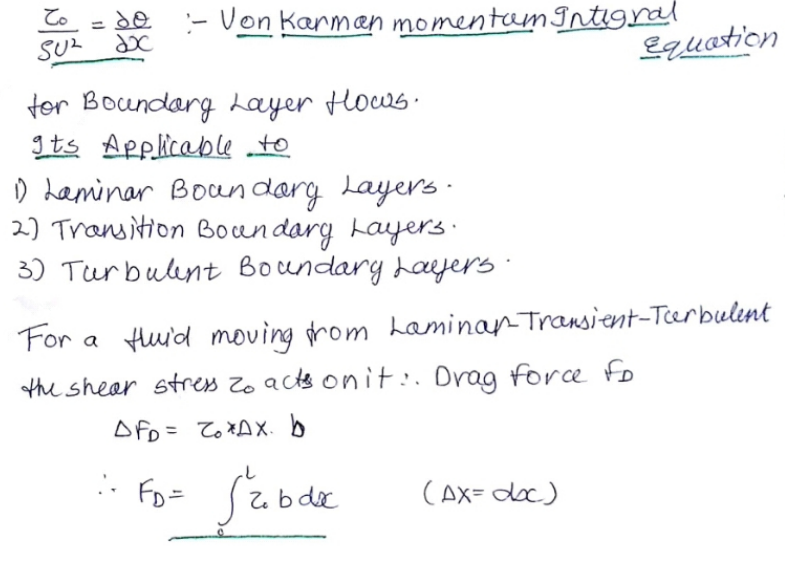
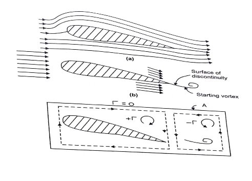


we get FL = pUL
= pU L( CU sin
  )
)
= 2  sin
sin  (LC)
(LC) 



defined by the following expressions: : FD =CD x LC x
FL =CL x LC x
OR
The lifting force acting on a body in a fluid flow can be calculated
FL = cL 1/2 ρ v2 A
where
FL = lifting force (N)
cL = lifting coefficient
ρ = density of fluid (kg/m3)
v = flow velocity (m/s)
A = body area (m2)
6.9 Development of lift
A fluid flowing around the surface of an object exerts a force on it. Lift is the component of this force that is perpendicular to the oncoming flow direction. It contrasts with the drag force, which is the component of the force parallel to the flow direction. Lift conventionally acts in an upward direction in order to counter the force of gravity, but it can act in any direction at right angles to the flow.
A fluid flowing around the surface of an object applies a force against it. It makes no difference wheather the fluid is flowing past a stationary body or the body is moving through a stationary volume of fluid. Lift is the component of this force that is perpendicular to the oncoming flow direction.
Lift is always accompanied by a drag force, which is the component of the surface force parallel to the flow direction.
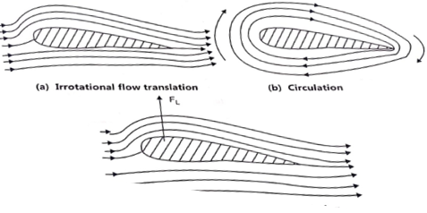
Lift is a result of pressure differences and depends on angle of attack, airfoil shape, air density, and airspeed.
Pressure differences-
Pressure is the normal force per unit area exerted by the air on itself and on surfaces that it touches. The lift force is transmitted through the pressure, which acts perpendicular to the surface of the airfoil. Thus, the net force manifests itself as pressure differences. The direction of the net force implies that the average pressure on the upper surface of the airfoil is lower than the average pressure on the underside.
These pressure differences arise in conjunction with the curved airflow. When a fluid follows a curved path, there is a pressure gradient perpendicular to the flow direction with higher pressure on the outside of the curve and lower pressure on the inside. This direct relationship between curved streamlines and pressure differences, sometimes called the streamline curvature theorem, was derived from Newton's second law by Leonhard Euler in 1754:
The left side of this equation represents the pressure difference perpendicular to the fluid flow. On the right hand side ρ is the density, v is the velocity, and R is the radius of curvature. This formula shows that higher velocities and tighter curvatures create larger pressure differentials and that for straight flow (R → ∞) the pressure difference is zero.
Lift on a Circular Cylinder:
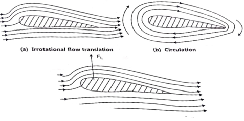
1. In the case of an ideal fluid passing past a circular cylinder, the flow pattern is symmetrical and hence there is no lift acting on the cylinder. The velocity at any point on the l or hE cylinder along the tangent to the cylinder is given by,
u = 2.U. sin 
2. If a constant circulation is imparted to the cylinder, the flow pattern around the cylinder will consist of streamlines in the form of concentric circles. In this case, the peripheral velocity is given by,
 =
=
3. The flow over a circular cylinder with constant circulation can be analyzed by the superimposition of the above two cases. The resultant flow pattern. The velocity at any point on the surface of the cylinder can be obtained by vectorial addition of the above two velocities as :
u = 2.U.sin +
+ 
4. For the upper half of the cylinder,  varies from 0° to 180° and sin e is positive and hence 2.U.sin e is positive. For the lower half, 2.U.sin
  is negative since sin e is – ve as
 varies from 180
 to 360°.
5. Thus the velocity around the upper half of the cylinder is higher than that on the lower half. Application of the Bernoulli's equation shows that the pressure on the lower half is higher than that in the upper half. As such there will be a force acting on the cylinder in the direction normal to the direction of flow.

1. The ratio of lift to drag is the slope of the line joining origin and point on the curve for which the ratio is to be found out.
2. The maximum value of lift to drag is given by the slope of the line tangent to curve drawn from origin.
3. The curve also shows the points of zero lift and point of minimum drag.
Reference books:
1. Engineering Fluid Mechanics by R. J. Garde and A.J Mirajgaonkar, Pub: SCITECH Publications( India )Pvt.Ltd, Chennai
2. Fluid Mechanics and its Applications, Vijay Gupta, Santosh K Gupta, New Age International Pvt. Ltd, New Delhi,
3. Fluid Mechanics, Fundamentals, and applications by Yunus. A Cengel and John.M Cimbala, Mc Graw Hill International, New Delhi.
4. Fluid Mechanics by Streeter, Wylie, and Bedford – Pub: McGraw Hill International, New Delhi.
5. Open Channel Hydraulics by Ven Tee Chow, Pub: Mcgraw- Hill Book Company- Koga.
6. A Text-Book of Fluid Mechanics and Hydraulic Machines- by Dr. R K Rajput Pub: S Chand and Co Ltd. New Delhi
