Unit - 1
Simple Stresses and Strains
1) Wood:
Wood or more appropriately timber is a fibrous product achieved from tress. Wood has been used as a binding material since ages in the form of boards, Planks or similar materials. Due to environment-friendly nature, it helps to build construction despite severity in climatic conditions.
Incredible properties associated with woods such as flexural strength under loads and sturdiness while bending. Wood holds diversified properties as a variation in climates and their sources. In earlier times woods has found its applications into sleepers of railways, building supports or braces.
Advantages:-
2) Glass:
Glass isn’t new material as we think about, it was invented in 3600 B.C. An excellent material prepared by heating Sand and Silicates at high temperature, lead to the discovery of this magnificent material. Glass has been helping humans to prepare to see through windows along with decorative purposes.
Innovations in glass have made it brittle proof and energy-efficient material in the construction industry. Glass has its extensive applications in creating “Space Frame”.
3) Ceramics:
Interior decorative material such as tiles and fixtures come under ceramics. Their prominent application could be found as covering a certain part of buildings or setting up fixtures. In general the most common of all them are walls paints, counter-tops, ceramic floors and even fall-ceilings come under ceramics.
A significant number of countries worldwide use ceramic flooring to cladding to buildings. In ancient time, ceramics were restrained to a special type of kiln manufacturing. In modern times, ceramics has technically as well functionally involved.
Advantages:
4) Paints:
Paint is a liquid surface coating which forms as a thin film on drying.
There are different types of paints, each of them chosen as per the requirement. Out of them, Oil paints, water paints, cement paints, bituminous paints and special paints such as fireproof paints, luminous paints, chlorinated rubber paints (for protecting objects against acid fumes) excessively used in the building construction, which in turn makes Paint is an important building material for the construction.
5) Polymeric Materials:
Rubbers, Plastics and resins used for the construction purpose are made with the polymeric materials. Polymers are macromolecules with high molecular weight having colloidal dimensions (10–3 to 10–6 mm in diameter) Small molecules called monomers undergo polymerisation reaction and form macromolecules.
6)Concrete:
The material of “Future”. World Most consumed material after water. Well, that’s how much significant concrete is. The combination of aggregate, sand and cement. Hydration of concrete leads to its hardening like a stone.
The consistent innovations in concrete have opened various untouched opportunities for customized concrete.
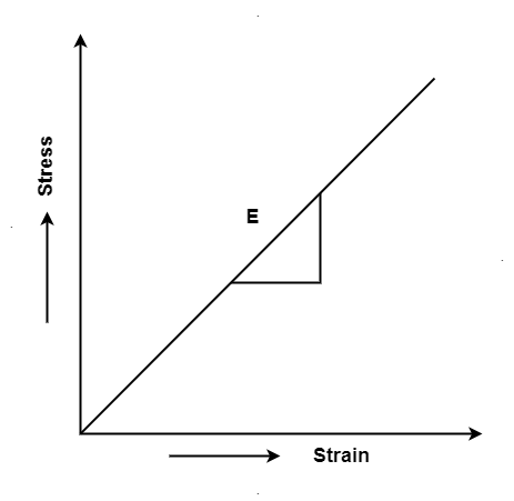
Hooke's law states that the strain of the material is proportional to the applied stress within the elastic limit of that material.
When the elastic materials are stretched, the atoms and molecules deform until stress is been applied and when the stress is removed, they return to their initial state
i.e., σ = E
Where,
σ is the stress
E is the modulus of elasticity also known as Young’s modulus
ε is the strain
When the stress is removed from the material, there are two types of deformation that can take place: plastic deformation and elastic deformation
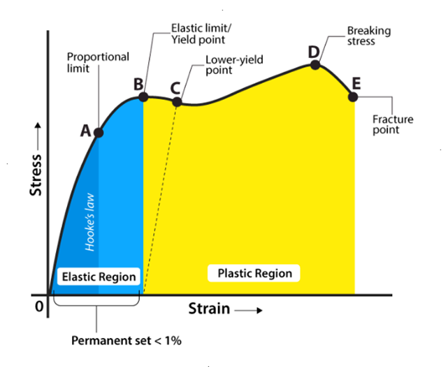
Explaining Stress-Strain Graph
The stress-strain graph has different points or regions as follows:
Proportional limit
Elastic limit
Yield point
Ultimate stress point
Fracture or breaking point
(i) Proportional Limit
It is the region in the stress-strain curve that obeys Hooke’s Law. In this limit, the ratio of stress with strain gives us proportionality constant known as young’s modulus. The point OA in the graph is called the proportional limit.
(ii) Elastic Limit
It is the point in the graph up to which the material returns to its original position when the load acting on it is completely removed. Beyond this limit, the material doesn’t return to its original position and a plastic deformation starts to appear in it.
(iii) Yield Point
The yield point is defined as the point at which the material starts to deform plastically. After the yield point is passed, permanent plastic deformation occurs. There are two yield points (i) upper yield point (ii) lower yield point.
(iv) Ultimate Stress Point
It is a point that represents the maximum stress that a material can endure before failure. Beyond this point, failure occurs.
(v) Fracture or Breaking Point
It is the point in the stress-strain curve at which the failure of the material takes place.
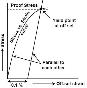
Above fig. shows a graph of stress against strain for brittle material when subjected to tension.
As already seen mild steel is the only material that shows a well-defined curve at each point.
Brittle material like concrete, aluminium, and cast iron has very low proportional limit and do not show the yield point.
In such a case where the yield point is not clearly defined it is taken as the point of some definite amount of permanent strain generally 0.2%. It is obtained by the offset method as shown in fig. The stress corresponding to the point B is called yield stress.
For brittle material the stress strain graph is continuous curve from the beginning itself as shown in fig. The ultimate stress is not well defined but breaking stress at the point A is well defined.
A brittle material has a relatively small tensile strain upto the point of rupture.
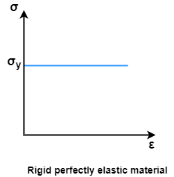
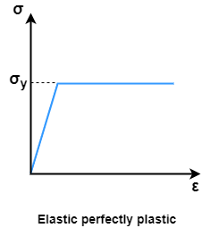
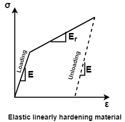
The stress analysis of the material based on linear elastic behaviour is insufficient increasing large number of technical problems.
To minimise problems, various stress strain curve are in used.
The three idealized stress strain curve is not commonly adopted as shown in fig.
You may have noticed that certain objects can stretch easily, but stretching objects like an iron rod sounds impossible, right? In this article, we will help you understand why few objects are more malleable than others.
Mainly, we will be discussing Stress-strain curves because they are useful in understanding the tensile strength of a given material. We shall learn how force applied to a body generates stress. In this article, let us learn about stress and strain definition and relationship between the stress-strain.
What is Stress?
In mechanics, stress is defined as a force applied per unit area. It is given by the formula
σ=F/A
Where,
σ is the stress applied
F is the force applied
A is the area of force application
The unit of stress is N/
Stress applied to a material can be of two types. They are:
● Tensile Stress: It is the force applied per unit area which results in the increase in length (or area) of a body. Objects under tensile stress become thinner and longer.
● Compressive Stress: It is the force applied per unit area which results in the decrease in length (or area) of a body. The object under compressive stress becomes thicker and shorter.
What is Strain?
According to the strain definition, it is defined as the amount of deformation experienced by the body in the direction of force applied, divided by initial dimensions of the body. The relation for deformation in terms of length of a solid is given below.

Where,
 is the strain due to stress applied
 is the change in length
L is the original length of the material.
The strain is a dimensionless quantity as it just defines the relative change in shape.
Depending on stress application, strain experienced in a body can be of two types. They are:
● Tensile Strain:
It is the change in length (or area) of a body due to the application of tensile stress.
● Compressive Strain:
It is the change in length (or area) of a body due to the application of compressive stress
When we study solids and their mechanical properties, information regarding their elastic properties is most important. These can be obtained by studying the stress-strain relationships, under different loads, in these materials.
1) Linear strain

i.e.
 Strain
 change in the length of the body
 original length of the body
2) Lateral strain

Lateral strain  or
or =
= 
3) Shear strain
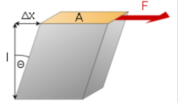

4) Volumetric strain


Where  change in volume and
 original volume
 by partial differentiation


i.e, 
i.e, 
where 


A. Uni - Axial Loading:
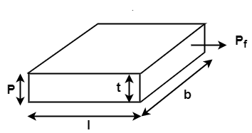
Case - I: Volumetric strain in Rectangular Bar:
Let L = Length of bar
b = width of the bar
t = thickness of the bar
p = Load applied in  dim
dim
(i) Stresses:

(ii) Strain:


 Volumetric strain of Rectangular bar is


B. Biaxial stresses:
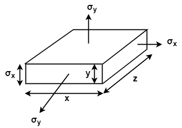
Consider a Rectangular member which is subjected to stresses in two dims  due to forces
  acting on it


C. Tri – Axial loading:
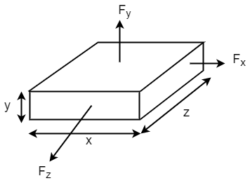
Let  be stresses in three dimension


Different elastic constants are as follows:
1. Young’s Modulus
According to Hooke’s law, when a body is subjected to tensile stress or compressive stress, the stress applied is directly proportional to the strain within the elastic limits of that body. The ratio of applied stress to the strain is constant and is known as Young’s modulus or modulus of elasticity.
Young’s modulus is denoted by letter “E”. The unit of modulus of elasticity is the same as the unit of stress which is megapascal (Mpa).
1 Mpa is equal to 1 N/mm2.

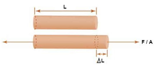
Fig: Body Subjected to Tensile Stress
2. Bulk Modulus
When a body is subjected to mutually perpendicular direct stresses which are alike and equal, within its elastic limits, the ratio of direct stress to the corresponding volumetric strain is found to be constant.
This ratio is called bulk modulus and is represented by letter “K”.
Unit of Bulk modulus is Mpa.

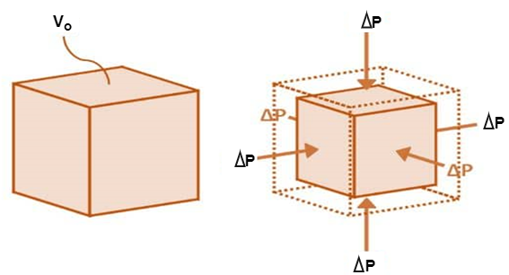
Fig: Volumetric Change of Body
3. Rigidity Modulus
When a body is subjected to shear stress the shape of the body gets changed, the ratio of shear stress to the corresponding shear strain is called rigidity modulus or modulus of rigidity.
It is denoted by the letters “G” or “C” or “N”.
Unit of rigidity modulus is Mpa.

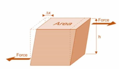
Fig: Shear Deformation of Body
4. Poisson’s Ratio
When a body is subjected to simple tensile stress within its elastic limits then there is a change in the dimensions of the body in the direction of the load as well as in the opposite direction.
When these changed dimensions are divided with their original dimensions, longitudinal strain and lateral strain are obtained.
The ratio of the lateral strain to the longitudinal strain is called Poisson’s ratio.
It is represented by the symbol “µ”. Poisson’s ratio is maximum for an ideal elastic incompressible material and its value is 0.5.
For most of the engineering materials, Poisson’s ratio lies between 0.25 and 0.33. It has no units.
5. Relationship between Elastic Constants


1. Temperature Strain:
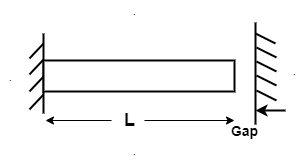
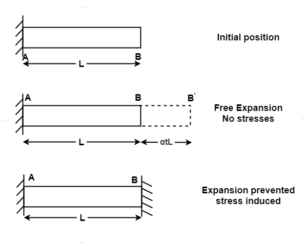
The Ratio of free expansion prevented to the original length of member is called as Temperature strain.


If supports are yield

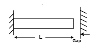
2. Temperature stress:
When Temp falls, the stresses induced are Tensile in nature
We know , 


Where, = Coefficient of thermal expansion in 1 C or 1
 k
k
T = Temperature Variation in  or K.
or K.
E = Young’s Modulus,
1. Temperature Stress in Members in Parallel [Composite Section]
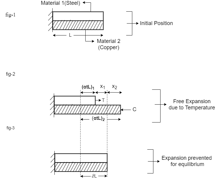
Consider a composite member formed by joining a steel rod and copper rod as strain in fig (1)
If both the materials are allowed to expand freely then change in length of copper will be  and in steel
  .
.
Let  Refer fig (2)
When Equilibrium is reached, the tensile force exerted by copper on steel will be equal to compressive force exerted by steel on copper Refer fig (3).
For a composite section final deformation is same. i.e., If  and temperature rises.
Compression in Material 1 = Tension in Material 2

Total elongation of steel = Total elongation copper
 [Elongation due to Temperature + Elongation due to Tensile force
 [Elongation due to Temperature - Elongation due to Composite force

Total Strain 
Deformation 
2. Composite Member in Series:
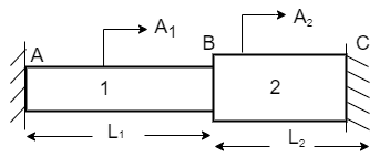
Consider a member ABC is held in supports at A and C as shown in figure (1).
When temperature is raised compressive stresses are developed in each portion and when temperature is lowered tensile stresses are developed in each portion.
Let  Young’s Modulus of portion 1 & 2.
 Coefficient of linear expansion in 1 and 2.
Free Expansion due to temperature variation.
BB’ and CC’ is the free expansion of member 1 and 2.
 Free expansion =
  (a)
(a)
Let R be the re exerted by the supports
Deformation due to reaction  (b)
(b)
 Equation of Compatibility,
Free Expansion – Deformation due to reaction =0
Free Expansion = Deformation due to reaction

If supports are yields,
Free expansion due to temperature – Gap =Deformation due to reaction

References: