Unit - 3
Shear and Bending Stresses
1. Concept of shear:
The shear force at the cross section of a beam is defined as the algebraic sum of all the unbalanced vertical forces either left or right of the section.
SF = (∑ Fy)L = (∑ Fy) R
Sign convention for shear force:
An upward force to the left of section or downward force to the right of a section will be considered as a positive shear force.
When the force is downward to the left side of section and upward on the right of a section, will be considered as a negative shear force.
2. Complimentary shear:
Principle of complementary shear stresses
In order to balance the rectangular block, there must be one more couple of similar intensity acting over the rectangular block in opposite direction i.e. in anti clockwise direction.
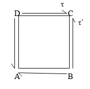
Let us keep in mind a square block ABCD as displayed in following figure. Let us expect that a fixed of shear stresses (τ) of contrary course, as displayed in following figure, is implemented over the other surfaces of square block i.e. AB and CD.
Now if we keep in mind the impact of this set of shear stresses (τ) of contrary course, we are able to effortlessly say that there could be 0 internet pressure performing over the square block however there will be one couple performing over the square block in clockwise course.
In order to stability the square block, there need to be one greater couple of comparable depth performing over the square block in contrary course i.e. in anti-clockwise course. Therefore, there could be one greater set of shear stresses (τ’) of identical depth performing over the relaxation contrary surfaces of square block and this set of shear stresses could be termed as complementary shear.
3. Derivation of shear stress formula:
Consider a small portion ABCD of length dx of a beam with bending moment varying from m to m=dm due to udl over its length dx
The distribution of compressive stresses due to bending moment shown in fig
Let
M = bending moment at AB
M + dM = bending moment at CD
F = shear force at AB
F+ dF = shear force at CD
Consider element strip EF at a distance y from the neutral axis as shown in fig.
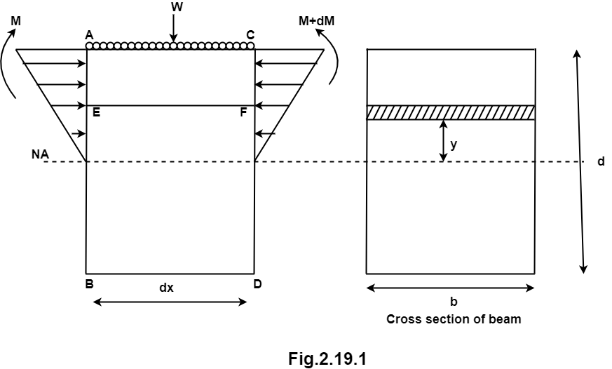
Let
σ = bending stress across AB at a distance y from neutral axis
σ + d σ = bending stress across
I = moment of inertia
By using flexural formula

On face AB, 
On face CD, 
Face acting across AB 
Similarly, force acting across CD, 
Net unbalanced force on the strip

The load unbalanced force F above neutral axis can be found out by integrating from 0 to d/2


 But ∫ y x dA= first moment of area under consideration from neutral axis= Ay
 F = dM/ I x Ax y
This unbalanced force is balanced by a shearing stress 𝜏 acting along the length dx and width b,
Shear stress = shear force/ shear area


But 

Where,
S = shear force at the section under consideration
A = area above or below the layer under consideration
 y = distance of centroid of area under consideration from neutral axis
b = width at the layer under consideration
I = moment of inertia of the section.
1. Shear stress distribution over a circular section:
Consider a circular section of diameter d as shown in fig.
Diagram
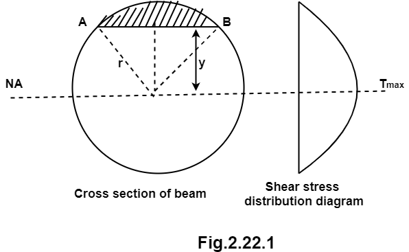
The shear stress on a layer AB at a distance is given as,

Width of strip AB in a circular section

Where, r= radius of circular section
Area of shaded strip =
Moment of area about neutral axis =
The moment of whole shaded area about neutral axis

But 

Again, 
Squaring both side
2b db = 4(-2y) dy

Substituting the value of y.dy in equation (i)

We know that, when y= r. and b = 0
The limit of integration may be changed from y to r, from b to 0 in equation (i)


Now substituting Ay in shear stress formula


Observations from above equation
From Equation (iii) shear stress 𝜏 increases as y decreases
At y = 𝜏 𝜏 = 0
At y = 0 𝜏 is maximum

Put r= d/2

put I = 𝛑/64 d4


Therefore,


2. Shear stress distribution over a rectangular section:
Consider a beam of a rectangular section of width b and depth d as shown in fig.

Shear stress at any layer CD of beam at a distance y from the neutral axis

Where,
S = shear force at the section
A = Area of beam above y
 y = Distance of centroid of shaded area from neutral axis
I = Moment of inertia of the section
b = Width of section CD
Area of shaded portion 
Distance of centroid of area from neutral axis


Moment of inertia 
Shear stress at any layer CD


From above equation we can observe that,
𝜏 increases as y decrease
Variation of 𝜏 is parabolic as the equation in of second degree
When y = d/2, 𝜏 = 0
When y= 0, 𝜏 is maximum
The variation of shear stress across the depth of the beam is parabolic.
Shear Stress
At top and bottom, y= d/2 
At neutral axis, y= 0


Where

Example 1]
A beam of rectangular section is 100 mm wide and 200 mm deep. If the section is subjected to a maximum shear force of 10000 N. find the maximum shear stress. Also draw the shear stress distribution across the section.
Solution:
Given: b= 100 mm, d = 200 mm, S = 10000 N
To find: 
Moment of inertia


Maximum shear stress


1. Theory of simple or pure bending:
When the beam is subjected to a constant bending moment no shear stresses are induced in that portion of beam is called as simple bending or pure bending.
A simply supported beam ABCD subjected to two equal point load w at equal distance ‘a’ from each support.
In this chapter we are considering the beam is subjected to pure bending only. i.e. shear force neglected.
In shear force diagram the shear force between portion BC is zero.
In bending moment diagram the bending moment between portions BC is constant. The portion BC is said to be under pure bending.


2. Assumptions:
1. The material of beam is homogeneous and isotropic. (isotropic means having the properties same in all direction.)
2. The beam is straight before loading.
3. The beam is uniform cross section throughout its length.
4. Transverse section which is plane before loading remains plan even after loading.
5. The material is elastic and hooks law is applicable.
6. The effect of shear is neglected therefore the analysis is meant for pure bending.
7. The modulus of elasticity E has same value in tension and compression.
8. Each layer is free to expand or compact having no influence in the neighboring layers for their extraction and contraction.
9. The beam is initially straight and all longitudinal filaments bend into circular area with a common center of curvature.
3. Derivation of flexural formula:

Fig. Before Bending
Consider any two normal sections AB and CD of a beam for a small length ‘dx’ apart as shown in fig. After the application of the transverse loading on the beam will be bends A B
Let AB and CD intersect each other at ‘O’

Fig. After Bending
Let,
R = Radius of curvature of the neutral layer EF
θ = subtended angle at ‘O’
Consider a layer GH at a distance y from neutral axis
Stain in layer GH due to bending
e = change in length/ original length
 = GH-GH
GH
But GH = EF
From Fig.
Length of arc = subtended angle x radius
Original length EF = EF = R θ
Length of layer GH = (R + y) θ
Change in length = GH - GH = (R + y) Θ - R θ


By definition, modulus of elasticity,

From equation (i) and (ii)


Since E and R are constant, the stress is directly proportional to the distance from neutral axis (N, A)
Now consider cross section of the beam consider an elementary strip at ‘y’ from N.A. and area of the strip ‘dA’
Force on the strip = stress on the strip x area on the strip


Moment of this force about N.A


Total moment of whole section about N.A

But  = Moment of inertia about neutral axis


From equation (iii) and (iv) we get,

This is known as bending formula or flexural formula
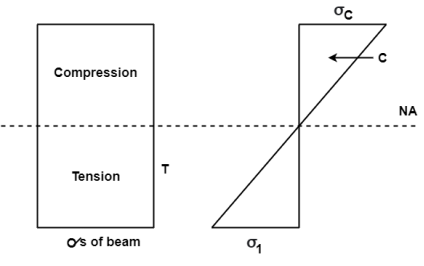
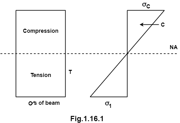
Whenever a member subjected to transverse loading, the nature of stresses above and below neutral axis is changes. The variation of bending stress is linear and maximum at extreme fiber. The diagram showing variation in stress across the depth of member is called as bending stress distribution diagram.
The couple which produced tensile stress on tensile zone and compressive stress on compressive zone of the beam to resist the bending moment due to external loading is called as moment of resistance. It is denoted by M.R.
Moment of resistance is always opposite to the bending moment
When the bending moment is greater than moment of resistance the member will fails.
For equilibrium bending moment is always equal to moment of resistance.
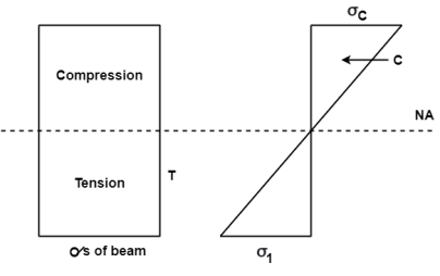
B.M = M.R


It is also defined as the product of sectional modulus and allowable bending stress.
References: