Unit - 4
Torsion of Circular Shaft and Principal Stresses and Strain
1. Theory of torsion:
2. Assumption made in the theory of torsion:
3. Derivation of torsion formula:
Consider a shaft of radius R and length L is subjected to torque T on the free end and other end is fixed.
Initially the line of the shaft is horizontal AB before twisting and after twisting it takes position AB’ as shown in fig.
Shear strain <BAB’ =  and Angle of twist <BOB’ =
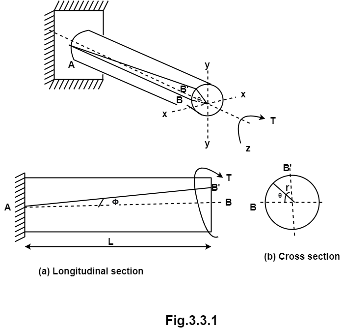
For longitudinal section,
tan  =
=  tan
tan =
= 
BB’=L ………………..(i)
From cross-section,
Length of arc = Radius  Angle tan
BB’=r …………….(ii)
From equation I and ii
L = r
= r
 ………….(iii)
By definition shear modulus,
G= =
=
 ……..(iv)
Equation for (iii) and (iv),

 =
=  …………….(v)
Maximum shear stress occurs at radius R.
 =
= 
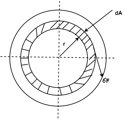
Now consider elemental ring of area dA at radius r from centre O.
Shear force on elemental ring = Stress  Area
Area
dF = 
 dA
dA
Torsional moment on ring,
dT = dF  r =
r = 
 rdA)
rdA)
dT =  dA
dA
Now torsional moment on whole sectional,
 =
=  dA
dA
But we know,  dA = polar moment of inertia = J
T = 
 J
J
 =
= 
From equation (vi) and (vii), we get,
 =
=  =
= 
Ans:
Given:
Tensile test: D = 15mm P = 40KN
 = 0.5 mm L = 500 mm

 = 45Mpa D = 50 mm
 = 0.4
= 0.4 L = 300mm
To find: 
(i) Modulus of elasticity from tension test.
E =  =
=  = 226.35
 Mpa
Mpa
(ii) Shear modulus from torsion test:
G =  = 77.35
  Mpa
Mpa
(iii) Passions ratio
E = 2G(1+ )
)


 = 1.463-1 = 0.463
2. A hallow circular of 200mm external diameter, thickness of metal 20mm is rotating at 180rpm. The angle of twist of 3m length was found to be 0.7 . Calculate the power transmitted and maximum shear stress induced in the material. Take G = 80
 Mpa.
Mpa.
Ans:
Given
D = 200 mm
t = 20 mm
N = 180 rpm
L = 3m = 3000 mm
 = 0.01222 radian

Internal diameter d= D – 2t = 200 - 2 20 = 160 mm
 =
= 
T = 30.2208 
 N.M
N.M
Power p =  = 569.65 KW
It is the average torque and corresponding angle turned per unit duration of time.
Power = Average torque  Angle of rotation/sec.
P = T 

P = 
Where, T = Average (mean) torque in N-m.
N = No. of revolution per minute(rpm)
2. Principal stress:
3. Major Principal stress:
4. Minor Principal Stress:
5. Major Principal Plane:
A plane which carries major principal stresses is called as major principal plane.
6. Minor Principal Plane:
A plane which carries the minor principal stress is called minor principal plane.
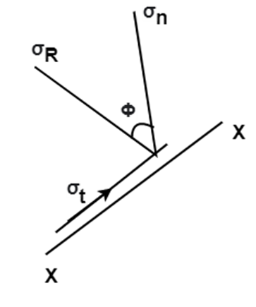
The resultant of the normal stress and the tangential stress is called as resultant stress. It is denoted by  .
.

Where, 
 = Tangential stress
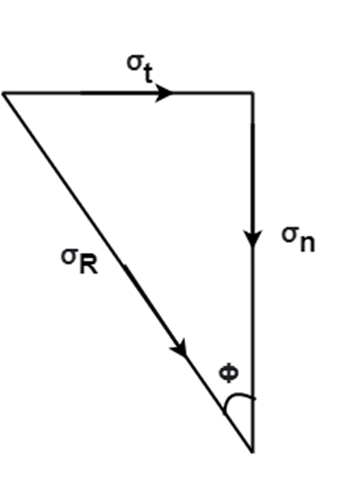
The angle made by the resultant stress with the normal stress is called as angle of obliquity.
It is denoted by 
tan =
= 
2. Stresses on oblique section of body
Following are the various cases, for determination of stresses on an oblique section of a body:
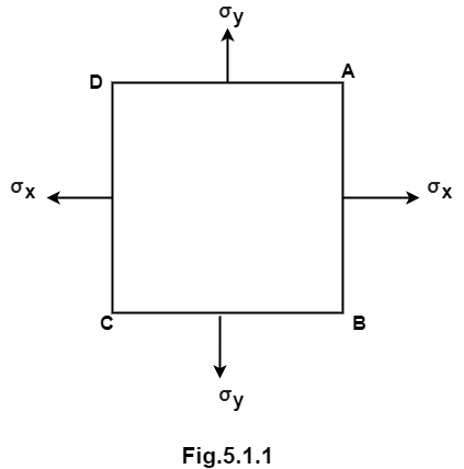
Consider a rectangular element ABCD of uniform cross-sectional area and unit thickness as shown in fig.
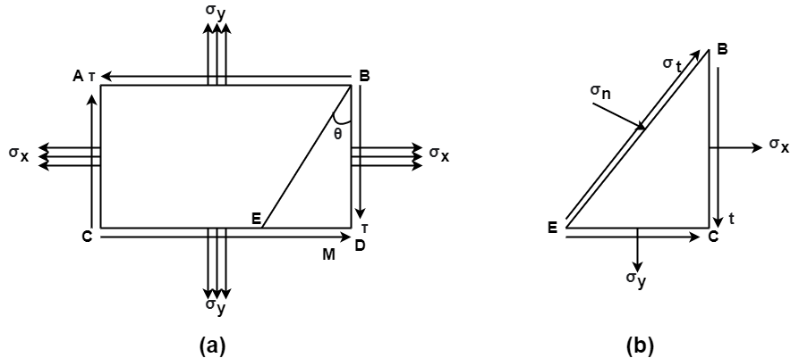
It is subjected to two normal stresses  and
and  and a shear stress
  .
.
Consider a plane BE inclined at an angle  to face BC as shown in fig.
Horizontal force on face BC = Stress on BE  Area =
  (BC
(BC  1)
1)
Vertical force on CE =  (CE
(CE  1)
1)
Vertical force on BC due to,
Shear Stress  =
= 
 BC
BC  1
1
Horizontal force on CE due to shear stress =
 CE
CE  1
1
From fig.

 Resultant normal forces,
 =
=  (BC
(BC )
) +
+  (CE
(CE  1)
1) +
+  (BC
(BC  +
+  (CE
(CE  1)
1) …………(i)

 =
= 
 =
=  +
+  +
+  +
+ 
 =
=  +
+  +
+  sin2
sin2 ……………(ii)
Resultant tangential force on plane BE, along x-axis.
 =
=  =
= 
 -
- 
 -
-  +
+ 
 =
=  sin2
sin2 -
- 
Resultant stress,  =
= 
Angle of obliquity  =
= 
2. Member subjected to direct stresses on two mutually perpendicular plane accompanied with shear stress.
Select the co-ordinate system representing direct stress on x-axis and shear stress on y-axis with origin at O.
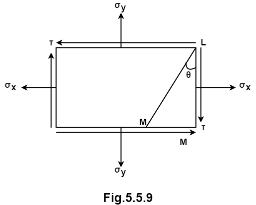
Locate point P and Q, OP =  and OQ =
Locate point R ( and S(
 )
)
Joint RS intersecting the x-axis at point C
 CP = CQ =

Radius of circle, R = 
The circle intersect abscissa at point A and B shear stress is zero.
References: