Unit - 6
Slope and Deflection of Beams and Trusses
1. Determinate Beam: the determinate beam is that the beam in which unknown support reactions can be calculated by using static equilibrium equations only.
Example: simply supported beams, cantilever beams, single and double overhanging beams.

2. Slope and Deflection of beams
Macaulay’s method
(Double ∫∫ method)
(Integration)
3. Basics:
1. Elastic curve: Deformed shape of beam is called as elastic curve.
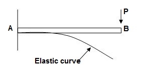
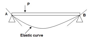
2. Slope: Angle made by tangent joint to the elastic curve with x-axis is called as slope.
3. Deflection: Translation of cross-section normal to the longitudinal axes of member is called as deflection.
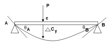
4. Reference System:
Left end of beam is taken as origin and reference system is as below.

5. Sign conventions:
(A). Slope
ϴ + dy/dx = Anticlockwise rotation of tangent
dy/dx = clockwise rotation of tangent
(B) Deflection
+y = upward Deflection
-y = downward Deflection
6. Flexural Rigidity = (EI)
Product of young modulus of elasticity and moment of inertia of cross-section is called as Flexural rigidity (FI).
Unit: KN.m2
Note: Slope and deflections are inversely proportional to FI.
7. Boundary conditions:
These are nothing but support conditions.
i) At fixed end:

dy/dx = 0
y = 0
ii) At hinged and roller end
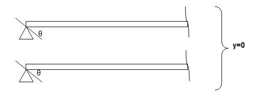
Q. Write boundary conditions for following beams
1) 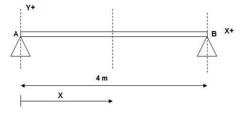
At x = 0; yA = 0
x = 4m; yB = 0
2)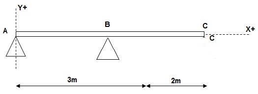
At x = 0; yA = 0
x = 3m; yB = 0
3)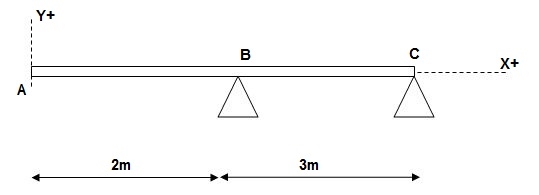
At x = 2m; yB = 0
At x = 5m; yC = 0
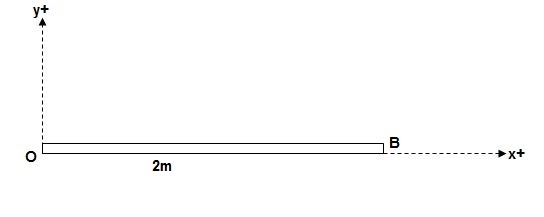
At x = 0; {dy/dx}A = 0
X = 0; yA = 0
8. Concept of Macaulay’s Method
We have,
M/I = 6/y = E/R
Where; R = Radius of curvature
= {1 + (dy/dx)2 }3/2 / d2y/dx2
For beams values of dy/dx are very small
R ≈ 1/d2y/dx2
M/I = E/R, E/1/d2y/dx2 = Ed2y/1 x dx2
M/I = Ex (d2y/dx2)
M = EI.d2y/dx2 = - - - - F(x) = BM eqn
ϴ = EI (dy/dx) = ----------- +c1 = slope eqn
Deflection EI(y) = --------- + C1(x) + C2 = Defneqn
‘’ (Eqn of elastic curve)
9. B.M equations:
Note:
For writing BM equation always consider section at a distance x from origin, placed in right extreme zone.
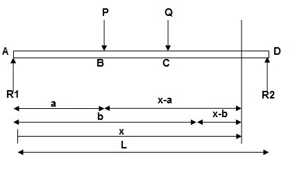
EI (d2y/dx2) = BMx = R1(x) | - P(x-a) | - Q(x-b)
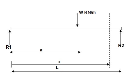
EI (d2y/dx2) = BMx = R1x | - w(x-a)2/2
EI (d2y/dx2) = BMx = R1(x) | - wx2/2 | + w(x-a)2/2
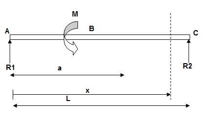
EI(d2y/dx2) = BMx = R1(x) | - M(x-a)
10. Procedure for Macaulay’s method:
i). Find support reactions
ii). Equations
iii). Find constants C1& C2 using boundary conditions
iV). Find slope &deflection
Notes:
1] Value of FI shall be substituted at the end of calculation in KN m2.
2] Answer for slope will be in radians and deflection in meter (m).
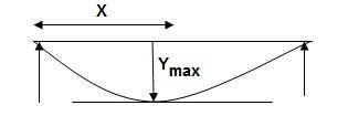
3] For simply supported beam at a section where deflection is maximum, slope is zero.
Example:
1) Given:
E = 200 GPa = 200 x 103MPa / N/mm2 = 200 KN/mm2
I = 3 x 108 mm4
EI = 200 x 3 x 108 KNmm2
EI = 600 x 102 KNm2
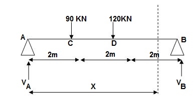
Reactions,
∑MA = VB(6) – 90 x 2 – 120(4) = 0
VB = 660/6
VB = 110 KN
∑Fy = VA + VB – 90 – 120 = 0
VA = -110 +90+120
VA = 100 KN
∑Fx = HA = 0
EI (d2y/dx2) = 100(x) | - 90(x-2) | -120(x-4) ---(1)
EI (dy/dx) = C1 + 100x2/2 | - 90(x-2)2/2 | -120(x-4)2/2 ---(2)
EI(y) = C1(x) + C2 + 100x3/6 | - 90(x-2)3/6 | -120(x-4)3/6 ---(3)
Boundary conditions:
At x=0 | yA = 0, put in (3)
C2 = 0
At x = 6m, yB = 0, put in (3)
6C1 + 100 x 36 – 90 x (4)3/6 – 120 x 23/6 = 0
6C1 + 3600 – 960 – 160 = 0
6C1 = -2480
C1 = (-) 413.33
Slope &Deflection:
X = 0, in (2),
(dy/dx)A = (-) 413.33/EI = (-)4133.33/600 x 102
 = 6.88 x 10⁻³ rad( )
X = 6m in (2),
EI(dy/dx)B = (-)413.33 + 100(6)2/2 – 90(4)2/2 – 120 x (2)2/2
= - 413.33 + 1800 – 720 – 240 = 426.67
 (dy/dx)B = 7.11 x 10⁻³rad( )
X = 2m in (3),
Yc = -413.33 x 2 + 100 x 23/6
= - 826.66 + 133.33
= -693.22/EI = -693.32/600 x 102 = -11.55
 Yc = -11.55 mm( )
X = 4m in (3)
yD = -413.33 x 4 + 100 x 43/6 – 90 x 23/6
= -706.6/EI = -706.6/600 x 102
= - 11.77 mm
 yD = 11.77 mm( )
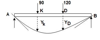
For maximum deflection
Let X > 2m
< 4m - zone CD
EI(dy/dx)CD = - 413.33 + 100/2x2 – 90(x-2)2/2 = 0
-413.33 + 50 x2 – 45(x-2)2 = 0
-413.33 + 50x2 – 45(x2-4x+4) = 0
-413.33 + 5x2 + 180x – 180 = 0
5x2 + 180x – 593.33 = 0
X = 3.03 >2m
<4m
Assumption is correct.
X = 3.03m in (3)
Ymax = -413.33 x 3.03 + 100(3.03)3/6 – 90 x (3.03-2)3/6
= -1252.38 + 463.63 – 16.39
= - 805.14/EI
2]. Given:
EI = 4 x 10⁴ Kn.m2
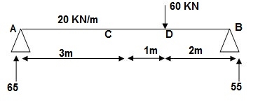
Reactions:
∑MA = 0
VB x 6 – 20 x 3 x x 1.5 – 60 x 4 = 0
VB = 55KN
∑Fy = 0
VA + VB – 60 – 20 x 3 = 0
VA = 65 KN
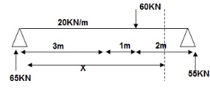
EI (d2y/dx2) = 65 x x | - 20 x x2/2 | + 20 x (x-3)2/2 | - 60(x - -(1)
EI {dy/dx} = C1 + 65x2/2 | - 20 x x3/6 | + 20(x - 3)3/6 | - 60(x - 4)2/2 - - (2)
EI(y) = C1(x) + C2 + 65x3/6 | - 20 x x4/24 | + 20(x-3)4/24 | -60(x-4)3/6 --(3)
Boundary conditions:
At x=0, yA = 0, put in (3)
C2 = 0
X = 6m, yB = 0 put in 3
C1 x 6 + 65 x 62 – 20 x 63/4 + 20 x 34/24 – 60 x 23/6 = 0
C1 = -207.91
Slope &deflection:
X = 3m in (2)
(dy/dx)c = -207.91 + 65 x 32/2 – 20 x 33/6 = -5.41/EI
= -1.35 x 10⁻⁴
 (dy/dx)c = 1.35 x 10⁻⁴ rad( )
X = 3m in 3
yC = -207.9 x (3) + 65 x (3)3/6 – 20 x 34/24 – 398/EI
= - 9.967 x 10-3
= -9.967mm
 yC = 9.967 mm( )
x = 4m in (3)
yD = -207.9 x 4 + 65 x 43/6 – 20 x 43/24 + 20/24
= - 350.7/EI
 = 8.76 mm ( )
3]. Given:
EI = 32.5 x 10³ Kn.m2

Reactions:
∑MA = 0
VB (5) – 45 x 3 x 1.5 + 30 = 0
VB = 34.5 KN
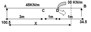
EI {d2y/dx2} = 100.5 x x – 45x2/2 | + 45 x (x-3)2/2 | -30(x-4)0 -- (1)
EI {dy/dx} = C1 + 100.5x2/2 – 45x3/6 | + 45 x (x-3)3/6 | - 30(x-4) --(2)
EI(y) = C1(x) + C2 + 100.5x3/6 – 45x4/24 | + 45 x (x-3)4/24 | - 3(x-4)2/2 --(3)
Boundary conditions:
At x=0; yA = 0 put in eqn3
C2 = 0
At x=5; yB = 0
5C1 + 100.5 x 53/6 – 45(5)4/24 + 45(2)4/24 – 30/2 = 0
C1 = (-) 187.375
Slope &Deflection:
X=3m in (2)
(dy/dx)c = -187.375 + 100.5 x 32/2 – 45(3)3/6
= 62.375/32.5 x 103
 (dy/dx)c = 1.919 rad( )
X = 3m in (3)
yC = -187.375 x 3 + 100.5 x 33/6 – 45 x 34/24
= - 261.75/32.5 x 103
= - 8.053mm
 yC = 8.053mm( )
x = 4m in (3)
yD = -187.375 x 4 + 100.5 x (4)3/6 – 45 x (4)4/24 + 45/24
= - 155.625/32.5 x 103
= - 4.78 mm
 yD = 4.78 mm( )
4]. Given:
E = 200 GPa
I = 6.2 x 107mm4
EI = 200 x 6.2 x 107 KN.mm2
= 200 x 6.2 x 107 x 10-6 KNm2
EI = 12400 KNm2
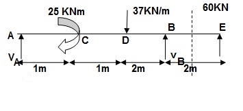
Reactions:
∑MA = 0
VB x 4 – 25 – 37(2)(3) – 60(6) = 0
VB = 151.75 KN
VA + VB – 60 – 37 x 2 = 0
VA = (-)217.75 KN
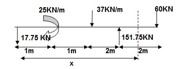
EI {d2y/dx2} = -17.75 x | + 25(x-1)0 | - 37 x (x-2)2/2 | + 151.75(x-4)2/2 | + 37 x (x-4)2/2 --(1)
EI {dy/dx} = C1 – 17.75x2/2 | + 25(x-1)| - 37(x-2)3/6 | + 151.75(x-4)2/2 | + 37(x-4)3/6 --- (2)
EI(y) = C1x + C2 – 17.75 x3/6 | +25(x-1)2/2 | -37(x-2)4/24 | + 151.75(x-4)3 | + 37(x-4)4/24 ---(3)
Boundary condition:
At x=0; yA=0 C2 = 0 (in eqn (3))
At x=4;yB=0 put in eqn(3)
4C1 – 17.75 x 43/6 + 25 x 32/2 – 37 x 23/6 = 0
C1 = 25.4
Slope and deflection:
X = 2m in (2) & (3)
(dy/dx)D = 25.4 –17.75 x 2 + 25
= 14.9/EI
 (dy/dx)D = 1.201 x 10⁻³rad( )
yD = 25.4 x 2 – 17.75 x 23/2 + 25/2
= 39.63/12400
 yD = 3.196 mm( )
x = 6m in (2) & (3),
(dy/dx)E = 25.4 – 17.75 x 62/2 + 25 x 5 – 37(4)3/6 + 151.75(2)2/2 + 37 x 23/6
= -210.183/12400
 = 0.017 rad( )
YE = - 341.7/12400 = 27.5mm
Key takeaways
1. Find support reactions
2. Equations
3. Find constants C1& C2 using boundary condition.
4. Find slope &deflection
the elastic force is an internal force in an elastic body that has certain special features which makes it distinct from most other forces including gravitational force in most cases in involving force the force ‘f’ is not a function of the displacement are of its p[point of application and hence the work done is given by a simple product of F and the scalar component of r in the direction F however in the case of an elastic body such as spring the displacement an the elastic force are mutually depends and are bound by a functional relationship for the purpose of computing “work” we usually treat the elastic deformation as the dependent variable and elastic force as the dependent variable as the deformation build a from zero to a maximum value the elastic force increases in sum definite a proportion in other word unlike other situation the elastic force is not a constant but varies while the displacement caused by it takes place.
Q] Find strain energy?
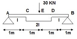
∑MA = 0
30 x 2 – RB x 4 = 0
RB = 15
VA = VB = 15 KN
BMC = BMD = 15(1) = 15 KN.M
BMC = 15(2) = 30 KN.M
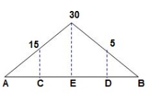
‘M/EI’ Dia.
C.B
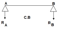
A1 = 1 / 2 x 1 x 15/EI = 7.5/EI
A2 = 2 x 7.5/EI = 15/EI
A3 = 1 /2 x 2 x 7.5/EI = 7.5/EI
A4 = 1 / 2 x 15/EI x 1 = 7.5/EI
Analysis of conjugate beam
∑MA = -RB (4) + 1/EI {7.5(2/3 x 1) + 15(2) + 7.5(2) + 7.5(3 + 1/31)} = 0
= - RB x 4 + 1/EI [5 + 30 + 15 + 25 ] = 0
RB x 4 = 75/17250
RB = 18.75/EI
∑fy = 0
-RA + RB + A1 + A2 + A3 + A4 = 0
RA = 18.75/EI
RA = RB = ½{A1 + A2 + A3 + A4} = 18.75/EI
Slope & Deflection
(ϴA)R.B = (SFA)C.B = (-)18.75/EI

 = 18.75/EI xC = 1.086 x 10⁻³rad xC

 (ϴB)R.B = (SFB)C.B = 18.75/EI xC = 1.086 x 10⁻³ rad xC
(ΔE)R.B = (BME)CB
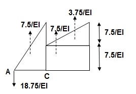
(BME)CB= 1/EI { -18.75 + 7.5(1 + 1/3 x 1) + 7.5(0.5) + 3.75 (1/3 x 1)}
=1/EI{-22.5}

 ΔE = 22.5/EI xC = 1.304 mm xC
Example:
1]. Find ϴC&ΔC= ?
Real Beam:
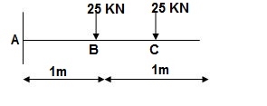
BMD :
BMA = -25(1) – 25(2) = -75KNm
BMB = -25(1) = -25KNm
BMC = 0
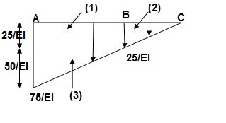
A1 = 25/EI x 1 = 25/EI
A2 = 1/2 x 1 x 25/EI = 12.5/EI
A3 = 1 / 2 x 50/EI x 1 = 25/EI
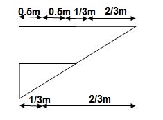
Conjugate beam:
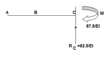
When force downward reaction is upward & when moment is clockwise in conjugate beam the moment is anticlockwise.
∑Fy = RC – 1/EI{25 + 12.5 + 125} = 0
RC = 62.5/EI
∑MC = - MC + 1/EI{25(1.5) + 12.5(2/3) + 25(1 + 2/3)} = 0
MC = 87.5/EI
Slope & Deflection
ϴC at Real Beam
(ϴC)RB = (SFC)C.B
=(-)62.5/EI
 ϴC = 62.5/EI ( )
(ΔC)RB = (BMC) CB
ΔC = (-) 87.5/EI
 ΔC = 87.5/EI ( )
2] Find: ϴA, ϴBand Δ centre= ?
Real Beam:
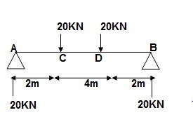
BMD : VA = VB = 20 KN
BMA = BMB = 0
BMC = BMD = 20 x 2 = 40 KNm
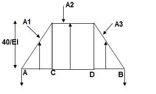
A1 = 40/EI = A3
A2 = 160/EI
Conjugate beam:
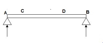
Reactions of CB:
RA = RB = ½(A1 + A2 + A3)
= 1/2EI (40 + 160 + 40 )
= 240/2EI
= 120/EI
Slope &Deflection:
(ϴA)RB = (SFA)CB = (-)120/EI
 ϴA = 120/EI ( )
(ϴB)RB = (SFB)CB = (+)120/EI
 ϴB = 120/EI ( )
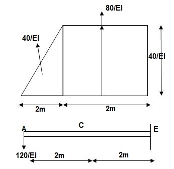
Shear force is zero -> Maximum BM(C.B)
BME = 40/EI x (2 + 1/3) + 80/EI(1) – 120(4)
= (-) 293.3/EI
 ΔE = 293.3/EI ( )
3] Propped cantilever and fixed beams by strain energy method
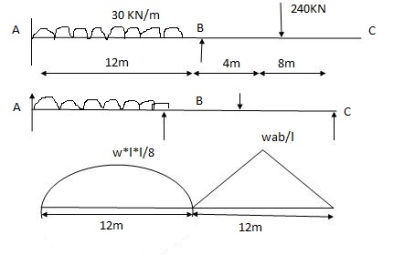


 A1 = 2 x wl2 x 12 = 2 x 30 x 122 x 12 = 4320 mm2
3 3 8


 x1 = l1 = 12 = 6 = 6m
2 2
A2 = 1 x wab x 12 = 1 x 240 x 4 x 8 x 12 = 3840 mm2


 2 2 12


 x1 = l2 = 12 = 6m x1 = L + a x2 = l +b


 2 2 3 3
Key takeaways:
It states that displacement at a point of application of load in the direction of load is equal to partial derivative of strain energy of structure with respect to load.
1]. ӘU/ӘQi = Δj
U = strain energy
Qj = Force in the direction j
Δj = Displacement in the direction j
2]. Strain energy: Uaxial force = ∫L0P2dx/2EA
UB.M = ∫L0M2dx/2EI
U Torsion = ∫L0T2dx/2GJ
Deflection = translation
3]. Procedure of displacement analysis by Castiglione’s theorem:
Step 1:
Apply imaginary load ‘Q’ at section where displacement is required.
Note:
1]. For horizontal translation apply
‘Q’ in horizontal direction
For vertical translation apply force Q in vertical direction
2]. For finding ‘slope’ (rotation) apply couple Q.
Step 2:
Find support reactions and draw member F.B.D’s
Step 3:
Prepare table:
Zone origin limits EI M ӘM/ӘQ
Step 4:
Find displacement using Δj = ∫L0M/EI{ӘM/ӘQj} dx
Find ΔB:

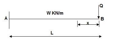
Zone Origin Limits EI M ӘM/ӘQ
BA B 0 to L EI –Q(x) – W(x2/2) -x
ΔB = ∫L0 M/EI(ӘM/ӘQ)dx = ∫L0{-W(x2/2)}(-x)dx
= W/2EI{x4/4}L0
 ΔB = WL4/8EI ( )
Examples:
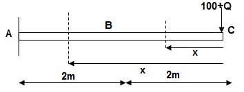
1]. Find Vertical deflection at ‘c’,
EI = constant
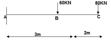
M Diagram
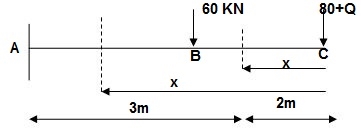
From above Fig:
Table
Zone Origin limits EI M ӘM/ӘQj
CB C 0-2 EI -(80 + Q)x - x
BA C 2-5 EI -(80 + Q)x - x-60(x-2)
ΔC = ∫20-(80)x/EI {-x}dx + ∫52{80x – 60(x-2) (-x)dx/EI}
= ∫2080x2/EIdx + ∫52{80x2 – 60x2 + 2x}dx/EI
= 1/EI {213.33 + 4200}
 ΔC = 4413.33/EI ( )
2] Find deflection at ‘C’
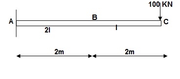
Solution:
M Diagram
Zone Origin Limit EI M ӘM/ӘQ
CB C 0 – 2 EI - (100 + Q)x -x
BA C 2 – 4 EI -(100 + Q)x -x
ΔC = ∫20 – 100x/EI(-x)dx + ∫42 -100x/EI(-x)dx
= ∫20100x2/EIdx + ∫42100x2/2EIdx
= 266.66 + 1866.6/2
= 266.66 + 933.33
For cantilever always write load from free end. For simply write load from supports.
ΔC = 1200/EI
3] Find slope at ‘A’, deflection at ‘C’.
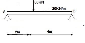
Solution:
M Diagram
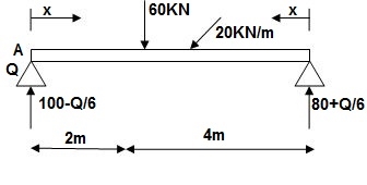
Reaction M dia.
∑MA = VB 6) – 20 x 6 x 3 – 60(2) – Q = 0
VB = 80 + Q/6
∑Fy = VA + VB – 60 – 20 x 6 = 0
VA = 100 – Q/6
Zone Origin limits EI M ӘM/ӘQ
AC A 0 – 2 EI (100-Q/6)(x) 1 – x/6+ Q – 20(x2/2)
BC B 0 – 4 EI (80+Q/6)(x)-20x2/2 x/6
ϴA = ∫20{100(x) – 10x2}{1-x/6} dx/dEI + ∫40{80x – 10x2}x/6dx/EI
= 1/EI{135.55 + 177.78}
 ϴA = 313.32/EI( )
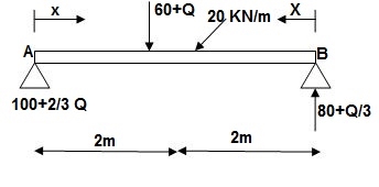
∑MA = VB (6) – 20(6)(3) – (60 + Q)2 = 0
VB = 80 + Q/3
∑Fy = VA + VB – (60 + Q) – 20(6) = 0
VA = -80 – Q/3 + 60 + Q + 120 = 0
VA = 100 + 2/3Q
4]. Find deflection at ‘C’

Solution:
i) M Diagram
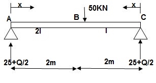
Zone Origin Limit EI M ӘM/ӘQ
AC A 0 – 2 EI (25 + Q/2)x x/2
BC B 0 – 2 EI (25 + Q/2)x x/2
ΔC = ∫20(25x)x/2dx/EI + ∫2025x(x/2)dx/2EI
= 33.33 + 16.66/EI
 ΔC = 50/EI( )
4] Slope & Deflection of Beams and frames by Castiglione’s 1st Theorem:
Q]. Find deflection at D
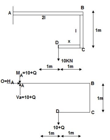
∑MA = MA – (10+Q)(1) = 0
MA = 10 + Q
∑Fy = VA – (10 + Q) = 0 VA = 10 + Q
∑Fx = HA = 0
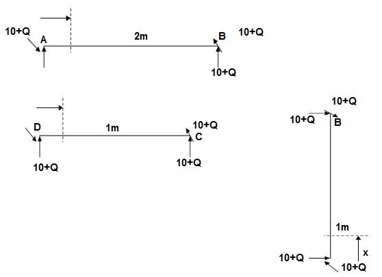
Zone origin limits EI M ӘM/ӘQ
AB A 0 – 2 2EI (10+Q)x-(10+Q) x-1
CB C 0 – 1 EI -(10 + Q) -1
DC D 0 – 1 EI -(10 + Q)x - x
ΔDy = ∫2 0(10x - 10) (x-1)dx/2EI + ∫10 -10(-1)dx/EI + ∫10 -10x(-x)dx/EI
= 3.33 + 10 + 3.33/EI
 ΔDy = 16.66/EI ( )
Key takeaways
1]. ӘU/ӘQi = Δj
2]. Strain energy: Uaxial force = ∫L0P2dx/2EA
3]. Procedure of displacement analysis by Castiglione’s theorem:
Step 1: Apply imaginary load ‘Q’ at section where displacement is required.
Step 2: Find support reactions and draw member F.B.D’s
Step 3: Prepare table: Zone origin limits EI M ӘM/ӘQ
Step 4: Find displacement using Δj = ∫L0M/EI{ӘM/ӘQj} dx, Find ΔB:
1. Unit load method:
The unit load method helps us in finding the displacement Dj at the j co-ordinate in a structure whose deformation are either known as or can be derived. in just rigid structure the internal displacement field is generally known in problems of indirect loading, such as due to environmental effect and constructional errors and it is desired to find a joint displacement that is compatible with the deformation more commonly we in counter problems involving direct actions where the deformations are not given but can be derived from the internal force response for example we can calculate bar elongations in truss members if we know the axial force in the bars similarly from the bending moment distributions in flexural members we can derived curvatures
Assuming linear elastic behavior we have the following well known relationships
Ei= fi X Ni
Where the subscript I refer to the ith bar whose axial flexibility fi is given by
Fi= li / (EA)
b. Between curvature  =
=  and bending moment m(x) in a flexural member.

2. Application of trusses:
Consider a truss with some displacement field which may be caused by direct or indirect loading. The elongation e in the bars known and it is desired to find some joint displacement Dj at the jth coordinate. If the cause is loading by direct action, the bar force Ni can be analyzed and the corresponding bar elongation ei are easily obtainable by applying ei= fi Ni
Diagram:
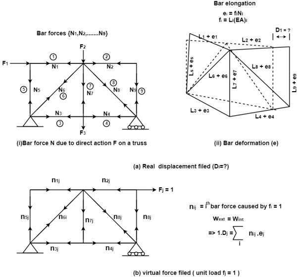
Fig. Application of unit load method to a truss
Now consider the some truss and apply a virtual unit load Fi=1 at the jth coordinate as shown fig. analyses the truss and arrive at all the virtual bar forces nj the force in the ith bar may be denoted as n0
Combining the real and virtual force field
External work
W ext. = Fj. Dj = 1.Dj= Dj
Internal work
W int. =∑ny ei
Applying the principle of virtual work W ext. = W int.
Dj = ∑ nij. ei
Note: that Dj has the same unit as ei is dimensionally homogeneous because the bar force nij is dimensionless having the unit KN/KN
Example:
Consider the pin jointed truss in fig. with bars member as indicated. Due to certain environmental changes bars 1 and 2 increase in length by 1.5 mm bars ‘3’ and ‘4’ increase in length by 3mm and bar 5 reduces in length by 1mm find the horizontal of (i) the roller support at D and (ii) the joint C.
Solution:
As the truss is jst rigid the environmental changes will be freely accommodated by the bars adjusting them self’s without introducing any force response. The bar elongation given from part of a real displacement field with
{e} = { + 1.5, + 1.5, + 3, + 3. – 1}t mm
The required horizontal joint displacement at D and C is identified as D1 and D2 resp. using the coordinate system so in fig.
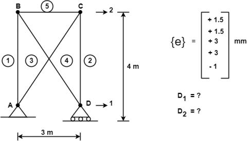
Applying unit load method, we create two separate virtual force fields with
F1 = 1 and F2 = 1 as indicated in fig.
Diagram
By the unit load method
D1 = ∑ni1 ei , D2 = ∑ni2 ei
Where ni1 and ni2 are the forces in the ith bar due to F1 = 1 and F2 = 1
Analyzing the truss for the two-unit load system we obtained the bar forces as


 {n1} = -4/3 {n2} = 0
-4/3 -4/3
+5/3 +5/3
+5/3 0
-1 0
Diagram:
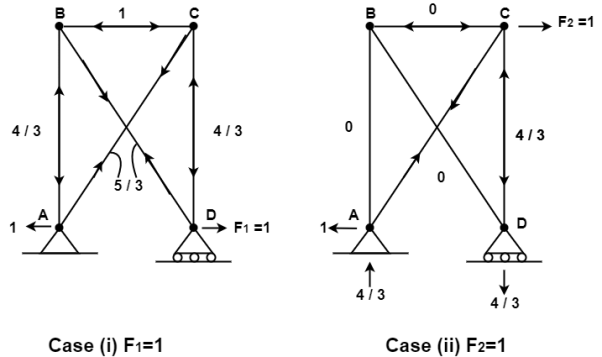
Therefore, the horizontal movement at the roller support is given by
Case (i) Horizontal deflection D1 of the support D
D1 = ∑ ni1 ei
= ( -4/3) ( 1.5+1.5) + ( 5/3) (3+3)+ (-1) (-1)
D1 = -4+10+1= +7mm
 D1 = +7mm ( )
Case (ii) Horizontal deflection D2 of the joint C
D2 = ∑ ni2 ei
= (-4/3) (+1.5) + (+5/3)(+3)
= -2+5= +3mm
 D2 = +3mm ( )
References: