UNIT - 3
PROPERTIES AND TESTING OF HARDENED CONCRETE
Introduction to Hard Concrete:
- The compressive strength of hard concrete is one of the most important and useful properties of concrete. In many structural applications, concrete is used primarily to withstand joint pressure. In cases where shear strength or tension is significant, compressive strength is often used as a measure of these properties. Concrete properties of composite ingredients are usually measured in terms of composite strength. It is also used as a quality measure for some hard concrete structures.
- There is no direct quality relationship between compressive strength and other factors such as strength, flexural strength, modulus elasticity, wear resistance, flexibility and fire resistance. However, some mathematical or solid relationships have been established between them for use in the field ministry. This relationship provides a limited number of these properties. It should be noted that the indicated strength of the concrete increases as the size of the template decreases, and the stiffness modulus falls.
- The modulus of elasticity therefore does not follow the compressive force. In cases where the concrete is subjected to cold and melting, the compressive strength does not reflect other useful properties of the concrete. Concrete containing about 6% of the air intake is very weak in compressive strength, but on the other hand it has been found to be much stronger than dense and durable concrete.
- The strength of concrete is a measure of its resistance to grief. Concrete strength can be measured as strength, compression, flexural or shear strength. All of these forces indicate a specific method of testing.
- When concrete fails under pressure, failure is actually a combination of crushing and shaving failure. Mechanical failure to resist concrete creates unity and internal conflict between the two. The development of cohesiveness and internal conflict with concrete is simultaneously the function of a single amount of water / cement.
The composition of the cement and the combination of the energy produced by the usable, well-balanced mix of ingredients are affected by the following:
(a) Water / cement ratio
(b) Cement / aggregate ratio
(c) Maximum size of aggregate
(d) Surface texture, shape, grading, Strength etc. Of aggregate particles.
Of the above factors, the water / cement ratio is the first factor affecting the strength of concrete. Some substances affect the water / cement ratio, thus indirectly affecting energy.
Water / Cement ratio:
The water / cement ratio can be indicated by weight and volume as well. By weight, the amount of water to be used per unit of cement (1 kg) is known as the water / cement ratio. If 500 grams of water are used per kilogram of cement, the water and cement ratio will be 0.5. Normally the water / cement ratio above 1.0 is not used. In terms of volume of water used per liter each bag of cement (50 kg) is considered as a measure of water / cement by volume.
Suppose 25 liters of water are used in each bag of cement, and the water / cement ratio is 0.5. In fact, the water / cement ratio is an indication of the strength of concrete. The strength of the concrete depends largely on the strength of the cement adhesive, and the strength of the cement adhesive depends on refining the cement cake. In other words the strength of the cement adhesive increases with the cement content and decreases with water and air content
In fully reinforced concrete, its strength is considered to be equal to the amount of water / cement that is equal. The normal curve of energy compared to the water / cement ratio is shown in the diagram. 8.1.
Abram's Water / Cement law
The great importance of concrete buildings was introduced after World War I and given additional pressure to build cheaper building materials. To maintain this objective it is considered that Duff Abram conducted extensive research and on the basis of his experimental results raised the relationship between the compressive strength of concrete and water / cement ratio in 1919
Kay takeaways
- The compressive strength of hard concrete is one of the most important and useful properties of concrete. In many structural applications, concrete is used primarily to withstand joint pressure. In cases where shear strength or tension is significant, compressive strength is often used as a measure of these properties. Concrete properties of composite ingredients are usually measured in terms of composite strength. It is also used as a quality measure for some hard concrete structures.
01. Water / Cement Measurement
The weight of the water and the weight of the cement is called the Water / Cement ratio. It is very important to find the strength of concrete. A low w / c ratio leads to a higher concrete strength. Generally, a water / cement ratio of 0.45 to 0.60 is used. Too much water leads to separation and leaves the concrete. The Water / Cement ratio is the opposite of the concrete strength. As shown in the chart below when the w / c ratio increases the concrete strength decreases and when the w / c ratio decreases and the strength of the concrete increases.
02. Concrete Compression
Concrete compaction increases concrete compaction because it is a process in which air void is released from newly formed concrete which makes the concrete cohesive and thick. The presence of air spaces in concrete greatly reduces its power. About 5% of air spaces can reduce energy by 30 to 40%. As we can see from the chart above, even the same amount of water / cement ratio differs in different assembly details. In fully compacted concrete, the strength is higher than sufficiently compacted concrete.
03. Concrete Ingredients
The main ingredients of concrete are cement, sand, composite and Water. The quality of each item affects the strength of the concrete. All materials, therefore, must carry out the normal process of concrete use such as,
(a) Type and Quantity of Cement
The amount of cement greatly affects the strength of concrete. High cement content increases the tendency for shrinking cracks when concrete is cured and hardened. Cement types have a significant impact on reinforced concrete structures. According to IS 456 2000, the minimum cement content is set to range from 300 to 360 kg per cubic meter of concrete of different exposure conditions and different grades of concrete. The high cement content of concrete is also limited to 450 kg per cubic meter of concrete. The level of cement - eg grade 33, grade 43, grade 53 will also affect the strength of concrete. The higher the distance, the higher the power especially the initial strength.
(b) Types and quantities of integration
The strength of concrete depends on the strength of the composite. The low quality of the mix reduces the strength of the concrete. The density of the joints also affects the areas of hard concrete. In regular cement content, a higher amount of composite reduces the strength of the concrete. The shape and arrangement of the joints play a major role in relation to the strength of concrete anxiety.
(c) Water Level
Water quality plays an important role in laying and strengthening the concrete process. Acid, oily, silty, and seawater should not be used in concrete mixes. Water pollution adversely affects concrete strength. Therefore, drinking water frequently used in concrete mixes, especially those impure water can lead to cracking, carbonation attacks or acid attacks, and, therefore, reduce the life of the concrete.
04. Concrete Healing
Concrete curing is very important to prevent plastic shrinkage, temperature control, increase strength and durability. The treatment provides the desired humidity and temperature at depth and near the surface after laying and finishing the energy-enhancing concrete. In other words, curing provides enough water for the concrete to complete the hydration process without significant disruption to energy development. A typical 7-day treatment is equivalent to 70% strength of the compression force. The healing time depends on the type of cement and the nature of the work. Generally, about 7 to 14 days of Ordinary Portland Cement. There are many healing methods such as immersion and immersion, spraying and covering with a complete wet cover etc.
So please remember, use as little water as possible during the mixing of concrete and use as much as possible after mixing.
05. Integration Status
There are many types of combinations such as angular, cubical, side, side and flaky, flaky, irregular and rounded.
Angular aggregates are easily engraved, and circular aggregates are smoothly engraved. Therefore, the round joint, creates the problem of lack of bonding between the concrete and the adhesive. Angular aggregates show a better concrete connection effect, but angular aggregate contains a larger number of voids. For this, you need a well-planned combination. The position of the aggregates is particularly important in the case of high strength and high concrete when a very low w / c ratio is used. In such cases, a combination of cubical shape with the same grading is required for better performance.
06. Maximum Aggregates
Larger size aggregates provide less energy because they have a lower potential to build a gel bond that is responsible for energy. The large size makes the concrete different. It will not distribute the same load when pressed. Due to internal bleeding, the problem of the development of small cracks in the concrete occurs when large-sized aggregates of concrete are used.
07. Placement of integration
Collection placement determines the particle size of the composite distribution. It is very important in the mixing of concrete. There are three types of Gap Graded Aggregate combined, poorly organized aggregate and Well-graded aggregate.
A well-placed collection contains all the particles of compound particles. Therefore, they have a small number of voids. The use of well-structured composites gives higher strength to concrete.
08. Weather
The weather also affects the strength of concrete for a variety of reasons. In cold weather, the outer concrete is subjected to repeated freezing and shaking due to sudden changes in the weather. It produces deterioration of concrete. With the change of moisture content, items are expanded and contracts. Produce cracks in concrete.
09. Temperature
With a certain increase in temperature, the level of the hydration process rises there, gaining energy faster. Sudden temperature changes create a hot gradient, which causes cracking and cracking of the concrete. In order, the final strength of the concrete is at a very high temperature.
10. The rate of loading
The strength of concrete increases with increasing load because at higher loading rates there is less time to skip .Creep produces continuous twists in the structure in regular loading. Thus, failure occurs in the weight limits rather than pressure. For fast loading, load resistance is better than slow loading.
11. Concrete Age
With the increasing years of concrete, the level of hydration will be greater. Hydration process is a chemical reaction of water and cement. Hydration produces a gel that plays a key role in the synthesis of concrete particles. Therefore, the strength of concrete increases with age .Generally, concrete strength doubles after 11 years as long as there are no adverse features.
Information on concrete strengths helps in many ways especially during construction, concrete construction choices, awareness of different weather conditions, choosing different composite methods, aiming for better structural health, lower building maintenance after construction, longer durability and better performance etc.
Key takeaways
Following are the factors affecting strength
01. Water / Cement Measurement
02. Concrete Compression
03. Concrete Ingredients
04. Concrete Healing
05. Integration Status
06.Maximum Aggregates
07. Placement of integration
08. Weather
09. Temperature
10. The rate of loading
11. Concrete Age
- Micro-Cracking concrete can be defined as the separation of individual concrete elements leading to obsolete materials. Depending on the size of the crack it can be divided into micro cracks, micro cracks, and semi-micro cracks.
- Geographically, cracks can be classified as bond cracks, mud cracks, and composite cracks. Bond cracks are formed in the visible mud connector and mortar, in which the cracks and mortar cracks are formed in the mud and on the scale, respectively.
- The knowledge of small cracks in concrete contributes significantly to the understanding of its non-clay nature, the descending part of the stress curve, the strength under the combined, repeated and continuous loading, etc.
- The continuous cracking of the concrete by the growing type is determined indirectly by measuring lateral-contraction expansion, surface cracking and sonic methods. The exact type of cracks and the problems that occur in them provide precise details about how to crack.
Minor effects of cracking with strong concrete
- The bond strength between the compound and the mud will be minimal.
- The compressive strength of the concrete will be small but does not affect the strength of the concrete.
- Continuous cracks are produced, concrete handling capacity will be reduced.
- With continuous cracking of the concrete, increasing stiffness with lateral increases and after occasional compression will form.
- These cracks have very small cracks inside the concrete so the life of the concrete will be reduced.
- You need to understand something about micro cracking for two reasons. First, the water resistance of the concrete may be affected by the degree of micro cracking. The water flowing through these small channels apparently moves slowly, but when there is a lot of micro cracking where it occurs, the concrete object shrinks. That is especially important when the chloride ion in water can reach the hardening of the metal embedded in the concrete and cause corrosion problems.
- Another reason to be aware of this situation is that micro cracking can serve as a starting point for the development of large cracks. If you are deeply interested in this subject, a full explanation can be found in ACI 446.1R-91, “Fracture Mechanics of Concrete”. But the main point is that overloading or demolishing jobs can lead to a significant reduction in concrete. That facilitates the formation of large cracks and the repair of failures.
Cracking of concrete
- ACI 546R-04, "Guide to Concrete Removal," describes local microcrack manufacturing that may arise from concrete removal operations. Removal of concrete using impact tools may result in minimal microcracking damage (called damage) to the surface of the remaining concrete surface. Unless the damaged layer is removed, a weak plane can occur in the parent concrete under the repair bond.
- The repair guideline states that when "aggressive impact methods," such as breaker-mounted breakers, are used to remove concrete before repair, "left concrete must be repaired using a second method, such as cracking, damage blasting, or high water pressure, to remove any remaining material. also damaged.
- Micro cracking is also a nuisance when hitting solid concrete, such as doses or anchors. The comment was given to ACI 318-08, "Requirements for the Building Concrete Construction Code". Specifically he notes that "digging holes for anchors installed in the back can cause micro cracking," explaining that this is due to the limited range of distance requirements on the edge of the anchor.
Key takeaways
- Micro-Cracking concrete can be defined as the separation of individual concrete elements leading to obsolete materials. Depending on the size of the crack it can be divided into micro cracks, micro cracks, and semi-micro cracks.
- Geographically, cracks can be classified as bond cracks, mud cracks, and composite cracks. Bond cracks are formed in the visible mud connector and mortar, in which the cracks and mortar cracks are formed in the mud and on the scale, respectively.
Stress strain relationship
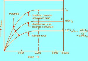
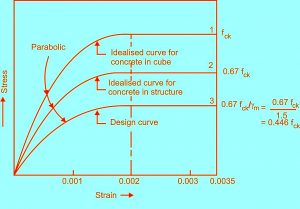
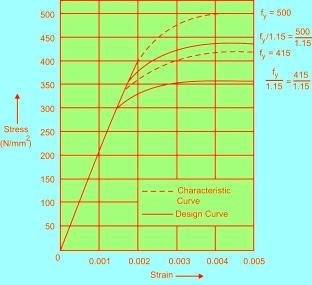
- Stress Strain Relationships with Concrete: Experimental or Real Stress Concrete Curve is very difficult to use in construction Therefore, IS code 456: 2000 has simplified or simplified
|
Fig no 1 Stress strain curve
- For design purpose, the compressive strength of the concrete in a structure is considered to be 0.67 times the strength of the element. The 0.67 element is introduced to justify the difference in strength shown by the test of the cube and the strength of the concrete in the actual structure.
- A fixed safety factor (rmc), equal to 1.5 was used in addition to this 0.67 factor.
- The first part of the curve is parabolic. After a hardness of 0.002 (0.2%), the pressure is constant with increasing load, up to 0.0035 and here it is indicated that the concrete has failed.
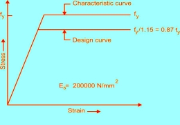
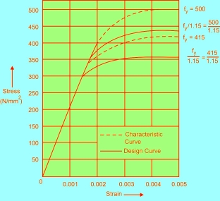
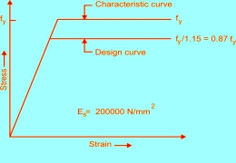
- Relationship of Stress Strain Iron: Pressure curve of mild steel, Fe 415 and Fe 500
|
|
Fig no 2 Stress strain curve for mild steel | Fig no 3 Stress strain curve of high strength deformed bars |
Relation between tensile and compressive strength
- The pressure of the concrete is eight times greater than its strength.
- This refers to the established relationship between the compressive strength and the strength of the concrete. In fact there is a close relationship but not a direct relationship.
- The degree of stiffness and pressure is low at high pressures.
- Experimental results also showed that concrete in stress and stress (both direct and indirect tension) is highly correlated but the relationship does not have a direct equation.
- The degree of strength and durability depends on the strength of the concrete.
- Thus, the increase in tensile strength, increases the tensile strength, but the rate of increase in tensile strength decreases steadily.
- The strength of concrete is more sensitive to improper treatment than to compressive strength.
This is possible for two reasons:
(a) The formation of a low-grade gel due to improper treatment.
(b) The formation of multiple shrinking cracks due to improper treatment. The use of pozzolanic materials showed an increase in strength.
- The Central Road Research Institute Delhi has conducted extensive research to build a relationship between the strength and durability of concrete in the construction of concrete roads.
- Based on the research experimental data, CRRI suggested the following relationship between flexural strength and concrete compression strength:
|
- Where is the compressive strength of M Pa concrete and x and its flexibility. This relationship depends on the size of the coarse aggregate. Energy is available to vary in type and quantity of composite.
Relationships are renewed below:
(a) With a crushed stone of 20 mm y = 15.3 x - 9.0 (b) 20 mm Natural Graval y = 14.3 x - 10.4 (c) For 40 mm Crushed Stones y = 9.9 x -5.5 (d) 40 mm Natural Graval y = 9.8 x - 2.5 |
Key takeaways
- The pressure of the concrete is eight times greater than its strength.
- This refers to the established relationship between the compressive strength and the strength of the concrete. In fact there is a close relationship but not a direct relationship.
- Abrasion resistance means the ability of building materials and structures to withstand scratches. It’s a way of dressing down or rubbing through a collision. This ability helps to maintain the true shape of the object and its appearance. Abrasion resistance is mechanical wear. Scratch-resistant materials are useful in both moving parts and adjusted to settings where wear is a problem.
- Abrasion resistance is very close to the compressive strength of the concrete. Strong concrete can withstand scratches than weak concrete. Resistance to abrasions of materials and building materials can be tested by a variety of testing methods.
- Abrasion resistant materials help prevent wear and tear on equipment. They can be used in the construction of spacecraft. Resistance to scratches of effective concrete is high. This silica-fume concrete is useful for paving the concrete road where heavy or severe congestion is found.
- Abrasion resistance is a material that allows the material to resist wear. Resistance to abrasion helps to withstand mechanical damage and often prevents the removal of the object from its surface. This allows the tool to maintain its integrity and maintain its shape. This can be especially important when the type of material is critical to its function, as seen when moving parts are carefully machined to make them more efficient. Abrasion resistance can be measured using an abrasion cleaning tester.
- Abrasion resistance can be controlled by:
- She uses appropriate cosmetics
- Covering objects with something that is resistant to abrasion
- Controlling the cause of the abrasion
- Wrong coverage is used
There are two types of abrasions in the uterus:
- Slide - to pass the area close to the rubber surface.
- Impingement - the wear of rubber by the hollow particles of sand.
When the rubber is not able to withstand the forces of society, scratches and wear can occur
Key takeaways
- Abrasion resistance means the ability of building materials and structures to with stand scratches. It’s a way of dressing down or rubbing through a collision. This ability helps to maintain the true shape of the object and its appearance. Abrasion resistance is mechanical wear. Scratch-resistant materials are useful in both moving parts and adjusted to settings where wear is a problem.
- Creep and thinning concrete are the two most visible features of concrete. The shrinkage of concrete, derived from calcium silicate hydrate (C-S-H) in a hardened Portland cement compound (which is responsible for mineral compounds), is quite different from the tilt of metals and polymers.
- Unlike metal cracks, it occurs at all levels of stress and, within the service level of stress, depends on what is stressed if the pore water content remains the same.
- In contrast to the eruption of polymers and metals, it exhibits several months of aging, caused by chemical hardening due to hydration that strengthens the formation of micro-organisms, and age-old aging, resulting in long-term resting of small equal pressure in nano- low CSH formation. When the concrete is completely dry, it does not move, but it is almost impossible to dry the concrete completely without severe cracking.
- Changes in water content in the pore due to dryness or watering processes cause significant changes in the volume of the concrete in non-load-bearing species. They are called shrinkage
- The age-old insect varies logarithmically over time (except for the final asymptotic value), and over normal life spans can receive values 3 to 6 times larger than the initial stretch problem. When deformation formation is abruptly induced and held inconsistently, the movement causes a break in the pressure produced in moderation. After discharge, increased recovery occurs, but in part, due to aging.
- In practice, travel during drying is inseparable from diminishing. The flow rate increases with the rate of change of pore humidity (e.g., vapor pressure associated with the pores). In the size of a small model, the penetration during drying far exceeds the total reduction of load without load and the penetration of the closed-loop template. The difference, called the drying creep or Pickett effect (or pressure-induced decrease), represents a hygro-mechanical between pore changes and pore humidity.
- The drying of the high humidity is mainly due to the pressure pressures on the solid microstructure that measure the increase in capillary tension and the surface tension in the pore walls. At low pore humidity (<75%), the shrinkage is caused by a decrease in the binding pressure across all nano-pores less than 3 nm in diameter, filled with indicated water.
- The chemical processes of Portland cement hydration lead to another type of shrinkage, called automatic shrinkage, which is detected in closed specimens, i.e., without loss of moisture. In part, this is due to changes in chemical volume, but especially energy loss due to the loss of water used by the hydration reaction.
- It achieves only about 5% of the dryness in normal cones, which self-desiccate about 97% of pore humidity. However, it can be equivalent to the reduction of drying in today's high-strength concrete containers with very low cement levels, which can cause the floor to have a humidity of less than 75%.
- The creep comes from calcium silicate hydrate (C-SH) attached to Portland cement. It is caused by slips due to breakage of bonds, by restoration of bonds in nearby areas. C-SH is highly hydrophilic, and has a colloidal microstructure separated from a few nanometers upwards. The paste has a porosity of about 0.4 to 0.55 with a large internal surface, about 500 m2 / cm3. Its main component is tri-calcium silicate hydrate gel (3 CaO · 2 SiO3 · 3 H20, abbreviated C3-S2-H3). The gel forms particles of colloidal size, which are weakly bound by van der Waals forces.
- How it works and modeling is still debated. The structural model in the following scales is not only available but at the moment has a very solid theoretical basis and fits very well with the full range of test data available.
Key takeaways
- Changes in water content in the pore due to dryness or watering processes cause significant changes in the volume of the concrete in non-load-bearing species. They are called shrinkage
- The compression take a look at indicates the exceptional feasible electricity concrete can gain in best conditions.
- The compression take a look at measures concrete electricity withinside the hardened state.
- Field concrete samples are organized, cured and examined consistent with ASTM preferred procedures.
- Specimens are organized from concrete taken from exclusive creation sites.
- Following methods and calculations are used for measuring compressive electricity of cylindrical concrete specimens.
Test Procedure
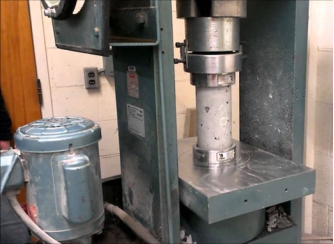
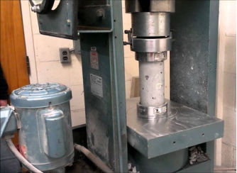
- Placing the Specimen — The plain (decrease) bearing block is located, with its hardened face up, at the desk of the trying out device without delay beneath the spherically seated (top) bearing block. The bearing faces of the top and decrease bearing blocks are wiped clean and the take a look at specimen is located at the decrease bearing block.
- Zero Verification and Block Seating— previous to trying out the specimen, it's far demonstrated that the weight indicator is ready to zero. If the indicator isn't always well set to zero, it's far adjusted.
- Rate of Loading— the weight is implemented constantly and without shock.
- Standards specify that for trying out machines of the screw type, the shifting head shall tour at a charge of about zero.05in. (1mm)/min while the device is jogging idle .While for hydraulically operated machines, the weight will be implemented at a charge of motion (platen to crosshead measurement) similar to a loading charge at the specimen in the variety of 20 to 50 psi/sec (0.15 to 0.35 M Pa/sec).
- During the software of the primary 1/2 of of the expected loading phase, a better charge of loading is allowed.
- No adjustment is made with inside the charge of motion of the platen at any time at the same time as a specimen is yielding swiftly right away earlier than failure.
- Load is implemented till the specimen fails, and the most load carried via way of means of the specimen all through the take a look at is recorded. The form of failure and the arrival of the concrete also are noted.
|
Fig no 4 Compression Testing Machine
Calculations:
Concrete Cylinder Loading Samples Compressive energy of the specimen is calculated through dividing the most load carried through the specimen all through the check with the common cross-sectional area.
Determine and specific the end result to the closest 10 psi (0.1 M Pa).
Key takeaways
1. The electricity of air-dried cores is on common 14 percentage large than the electricity of soaked cores.
Objective:
- To decide the Flexural Strength of Concrete, which comes into play whilst a avenue slab with insufficient sub-grade guide is subjected to wheel masses and / or there are extent modifications because of temperature / shrinking.
Equipment & Apparatus:
- Beam mildew of length 15 x 15x 70 cm (whilst length of mixture is much less than 38 mm) or of length 10 x 10 x 50 cm (whilst length of mixture is much less than 19 mm)
- Tamping bar (forty cm long, weighing 2 kg and tamping phase having length of 25 mm x 25 mm)
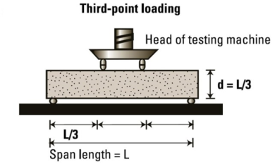
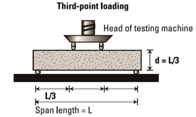
- Flexural take a look at gadget– The mattress of the checking out gadget will be furnished with metal rollers, 38 mm in diameter, on which the specimen is to be supported, and those rollers will be so hooked up that the space from centre to centre is 60 cm for 15.0 cm specimens or forty cm for 10.0 cm specimens.
- The load will be implemented via comparable rollers hooked up on the 1/3 factors of the assisting span that is, spaced at 20 or 13.3 cm centre to centre.
- The load will be divided similarly among the 2 loading rollers, and all rollers will be hooked up in this sort of way that the burden is implemented axially and without subjecting the specimen to any torsion stresses or restraints.
|
Fig no 5 Flexural testing machine
Procedure:
- Prepare the check specimen via way of means of filling the concrete into the mold in three layers of about identical thickness.
- Tamp every layer 35 instances the use of the tamping bar as distinct above.
- Tamping have to be disbursed uniformly over the whole cross section of the beam mildew and in the course of the intensity of every layer.
- Clean the bearing surfaces of the assisting and loading rollers , and get rid of any free sand or different cloth from the surfaces of the specimen in which they may be to make touch with the rollers.
- Circular rollers synthetic out of metallic having pass phase with diameter 38 mm may be used for presenting assist and loading factors to the specimens.
- The duration of the rollers will be at the least 10 mm greater than the width of the check specimen.
- A general of 4 rollers will be used, 3 out of which will be able to rotating alongside their very own axes.
- The distance among the outer rollers (i.e. span) will be 3d and the gap among the internal rollers will be d.
- The internal rollers will be similarly spaced among the outer rollers, such that the whole gadget is systematic.
- The specimen saved in water will be examined right away on elimination from water; while they may be nevertheless wet.
- The check specimen will be positioned with inside the device efficiently targeted with the longitudinal axis of the specimen at proper angles to the rollers.
- For mould specimens, the mold filling route will be ordinary to the route of loading.
- The load will be implemented at a price of loading of 400 kg/min for the 15.0 cm specimens and at a price of 180 kg/min for the 10.0 cm specimens.
Calculation:
O r
|
Where,
a = the gap among the road of fracture and the closer assist, measured at the middle line of the tensile aspect of the specimen
b = width of specimen (cm)
d = failure factor intensity (cm)
l = supported duration (cm)
p = max. Load (kg)
Safety & Precautions:
- Use hand gloves while, protection footwear on the time of check.
- After check transfer off the device.
- Keep all of the uncovered metallic elements greased.
- Keep the manual rods firmly constant to the bottom & pinnacle plate.
- Equipment have to be wiped clean very well earlier than trying out & after trying out.
Key takeaways
1. Beam mildew of length 15 x 15x 70 cm (whilst length of mixture is much less than 38 mm) or of length 10 x 10 x 50 cm (whilst length of mixture is much less than 19 mm)
- Indirect dynamic strength changes were tested from six samples: three dry samples and three samples exposed to water.
- During the indirect strength test, the sample is attached between two load strips and loaded freely at a speed of 50mm / min.
- The maximum load on the crack is measured. The relationship of energy values before and after water storage is determined, and is called the Indirect Tensile Strength Ratio (ITSR).
- Similar to the indirect strength test, a single-axial direct tensile test was initiated to investigate the strength structures of the study. Also, the strength was determined before and after preparing the test sample in the bath water according to EN 12697-12 B.
- The test samples used in this study included prismatic samples of the asphalt compound, as well as rods extracted from the rock and glued together with bitumen film.
- In the testing of dominant asphalt beams, every six beams are cut into slabs of composite asphalt composite (three dry, three wet). Adapters are attached with adhesives to the two parts of the sample surface.
- This is required to load samples into the machine. Strength strength is applied at a speed of 1.5mm / min at a temperature of 15 ° C. After the sample cracking, the strength of the strength is determined from high pressure, and the exact amount of strength strength (DTSR) accordingly.
- Similarly, direct strength testing was also applied to the extruded walls. on the rock covered and glued together the bitumen film.
- The power test is performed with different loading speeds and test temperatures. The broken sample.
- The materials investigated in this study include various types of bitumen (50/70, 70/100), bitumen modified polymer (PmB 40 / 100-65H, PmB 45A), of a wide range of natural materials from adhesive adhesives to adhesive markers. fine (basalt, Taunusquarzite, limestone, granite, gabbro), and four types of asphalt mixtures (AC 11, AC 16, SMA 11, PA 8).
- Details of the composite, bitumen-aggregate composites, types of asphalt composites and related tests. Preliminary tests have shown that high image quality is very important for reproduction, because both the base installation and the descent frame depend on contrast of the image brightness.
- Therefore, image quality was guaranteed by the introduction of low levels of brightness, contrast, and sharpness of the image as measured by DSA1 software.
- About 10% of the images produced failed to meet these standards and were not included in further analysis. A small number of usable metrics are defined as 30 data points per bit bitumen.
- The data only show slightly different outputs for multiple samples, with the exception of PE6506, and the standard deviation (SD) of the method generally compared the differences between the contact angles of different locations.
- To determine whether communication angles are very different or not, statistical testing methods have been used. The first Shapiro- Wilk test was used for standardized testing. It confirms the general distribution of data. Subsequently, variance analysis (ANOVA), in particular data was subjected to the F test.
- Including all samples tested, the F test rejected the absurd notion that communication angles are very different, i. e. a group of mediators is very different from each other.
- As the mean values of PE6506 deviated significantly from the data of other bitumen, the test was repeated without PE6506. The result shows that in this experiment only PE6506 can be separated from a number of other samples, which can also be separated between them.
- Pendant suction measurements are performed using five bitumen and bitumen precursors. Excess power is measured as a heat function.
- Linear regression analysis can be used in addition to other adjacent conditions because the samples show a very similar pattern at higher temperatures, but a different tendency to deal with lower.
- For example, the two releases include a 95% confidence interval time. Places are very advanced. The results of the addition of all the bitumen studied including error bars, which are found in the external confidence interval.
- The general overlap indicates that this method cannot distinguish between the tested samples. Therefore, the development of testing in relation to rebirth is necessary. The use of small glass slides as a basic model of bitumen-mineral aggregate interface has several advantages.
- First, the surface is perfectly smooth and chemically uniform. Second, the chemical properties of glass are similar to the composition of highly acidic minerals, which usually have a very high content of SiO 2.
- To test the strength of this test, two samples of bitumen (50/70 and 70/100) and a mixture of these bitumen and adherence agent were tested (50/70 + and 70/100 +). New drops of bitumen in the glass gave the same effect to all bitumen.
- After being stored at 70 ° C for 30 minutes, in addition to the bitumen softening points (50/70 and 50/70 +: 48 ° C; 70/100 and 70/100 +: 45 ° C) the results were different. Communication angles are very different from each other. The contact angles of pure bitumen are around 6 ° below the mixtures.
- This means, however, that wettabilities are worse with bitumen containing the input. The final variation of this test was the introduction of static water storage.
Key takeaways
- Indirect dynamic strength changes were tested from six samples: three dry samples and three samples exposed to water.
- During the indirect strength test, the sample is attached between two load strips and loaded freely at a speed of 50mm / min.
- Basic concrete testing is the most popular and well-established test method for the compressive strength of hard concrete. Critical concrete testing makes visual inspections of the internal parts of the concrete member also related to strength limitations Portable coring enables the inspection of other reinforced concrete structure structures with solid concrete testing
- In any case, the need to perform basic concrete tests often stems from the failure of concrete cubes / cylinders to get a realistic view of the strength of concrete as it exists in construction materials
Sampling of concrete core
It is very important that basic concrete samples are taken according to the guidelines given below
- Cores should be taken using pieces of diamond-filled spinal cord.
- Cores tested for power structures should have a minimum diameter three times the size design size of a rated set or 50 mm. whoever is great
- Where possible, cores tested for energy structures should be at least twice their length width
- As far as it is concerned that the reinforcing metal should not be inserted into the spine to be tested for strength. The size, number, and location of the metal reinforcement in the proposed primary area can be determined by using magnetic resonance imaging such as a retrieval meter (cover meter) or by ground-based radar testing or by using a pull-out radar system. If the spine contains a flexible reinforcing steel, a certain effect on the strength should be expected There is a possibility of a decrease in the strength of the concrete slab depending on the position of the steel. This effect is especially important when the metal is very far from the end of the set.
- As far as possible, the foundation pit should penetrate completely into the concrete section. This prevents spinal fractures and facilitates their removal. On the other hand, if drilling is not possible due to the size and configuration of the building in the area where the coring is planned, an additional 50 mm should be bound as a share of potential damage to part of the context.
- One root should not be used to diagnose a specific problem. When cores are taken gain power, a minimum of three characters need to be removed from each location. The amount of concrete strength in the hole should be taken as the benefit of these grains
- Special care needs to be paid when choosing a place for the concrete for standing concrete members such as walls, deep beams, etc. This is due to the differences in high-rise concrete structures due to differences in laying and mixing processes, separation, and bleeding. It is known that in general, the strength of concrete decreases as its height within the placement of membership increases.
- The exact history of structural treatment is often difficult to obtain so the effect of cooling the ammunition is also uncertain. When there is no wet treatment, no power expectations should be expected
- The direction of the ball also affects the strength of the bullets. Horizontally bound cores usually have lower power than direct bound calls,
- When cutting the core, the integrity of the concrete structure in the full section (c / s) is possible is affected to some degree. This feature should be taken into account when selecting a location where the file the core should be taken
Concrete Test procedure
Concrete pieces are usually cut with rotating cutting tools with diamond pieces. The cylinder sample is obtained by concluding its unequal pieces of equal parts, square, and embedded.
Cores are inspected visually to pay attention to the distribution of the composite, the compaction of concrete (non-air visibility), and the presence of metal, etc. The concrete slab should be soaked in water, soaked in melted sulfur so that it ends up parallel to the right angle. It is also tested on a pressure-testing machine in wet conditions in accordance with BIS 1881: Part 4: 1970 or ASTM 42-77.
Use of concrete core sample
- Water or gas leakage
- Chemical analysis
- ASHTO chloride permeability testing
- Determination of strength and resilience
- Depth of concrete installation
- Petro graphic Analysis
Key takeaways
- Cores should be taken using pieces of diamond-filled spinal cord.
- Cores tested for power structures should have a minimum diameter three times the size design size of a rated set or 50 mm. whoever is great
- Where possible, cores tested for energy structures should be at least twice their length width
Objective:
- The rebound hammer technique might be used for:
- assessing the possibly compressive electricity of concrete with the assist of appropriate correlations among rebound index and compressive electricity,
- assessing the uniformity of concrete,
- assessing the excellent of the concrete in relation to traditional requirements, and
- Assessing the excellent of 1 detail of concrete when it comes to another.
Principle:
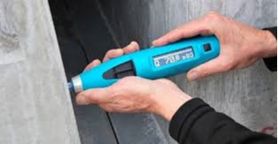
- When the plunger of rebound hammer is pressed in opposition to the floor of the concrete, the spring controlled mass rebounds and the volume of such rebound relies upon up on the floor hardness of concrete.
- The floor hardness and consequently the rebound is taken to be associated with the compressive strength of the concrete.
- The rebound is examine off alongside a graduated scale and is unique as there sure variety or rebound index.
Procedure:
- For trying out, smooth, easy and dry floor is to be selected. If loosely adhering scale is present, this have to be rubbed of with a grinding wheel or stone. Rough surfaces due to incomplete compaction, lack of grout, spalled or tooled surfaces do now no longer deliver dependable outcomes and have to be avoided.
- The factor of effect is to be at the least 20 mm far from any facet or form discontinuity.
- For taking a measurement, the rebound hammer is to be held at proper angles to the floor of the concrete member. The check can as a result be performed horizontally on vertical surfaces or vertically upwards or downwards on horizontal surfaces. If the state of affairs demands, the rebound hammer may be held at intermediate angles additionally, however in every case, the rebound variety may be unique for the equal concrete.
- Rebound hammer check is performed round all of the factors of remark on all on hand faces of the structural detail. Concrete surfaces are very well wiped clean earlier than taking any measurement.
- Around every factor of remark, six readings of rebound indices are taken and common of those readings after deleting outliers as consistent with IS: 8900-1978 turns into the rebound index for the factor of remark.
|
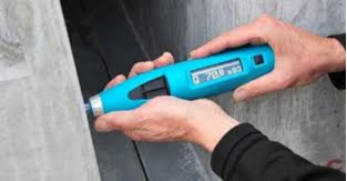
Fig no 6 Showing Rebound Hammer
Interpretation Of Result:
- The rebound hammer technique offers a handy and speedy indication of the compressive energy of concrete via organism appropriate correlation among the rebound index and the compressive energy of concrete. The process of acquiring such correlation is given in 4.2.
- It is likewise mentioned that rebound indices are indicative of compressive energy of concrete to a constrained intensity from the floor. If the concrete in a selected member has inner micro cracking, flaws or heterogeneity throughout the cross-section, rebound hammer indices will now no longer imply the equal.
- As such, the estimation of energy of concrete with the aid of using rebound hammer technique can't be held to be very correct and in all likelihood accuracy of prediction of concrete energy in a shape is ±25 percent.
- If the connection among rebound index and compressive energy may be checked with the aid of using assessments on center samples acquired from the shape or well known specimens made with the equal concrete substances and blend proportion, then the accuracy of consequences and self belief thereon are substantially increased.
Key takeaways
- The rebound is examine off alongside a graduated scale and is unique as there sure variety or rebound index.
- This take a look at is accomplished to evaluate the nice of concrete with the aid of using ultrasonic pulse pace technique as according to IS: 13311 (Part 1) – 1992. The underlying precept of this take a look at is –
- The technique includes measuring the time of journey of an ultrasonic pulse passing via the concrete being tested. Comparatively better pace is acquired whilst concrete nice is ideal in phrases of density, uniformity, homogeneity etc.
- Procedure to decide energy of hardened concrete with the aid of using Ultrasonic Pulse Velocity:
- Preparing for use: Before switching at the ‘V’ meter, the transducers ought to be linked to the sockets marked “TRAN” And ” REC”.
- The ‘V’ meter can be operated with either:
a) The inner battery,
b) An outside battery or
c) The A.C line.
- Set reference: A reference bar is supplied to test the tool zero. The pulse time for the bar is engraved on it. Apply a smear of grease to the transducer faces earlier than putting it on the other ends of the bar. Adjust the ‘SET REF’ manage till the reference bar transit time is acquired at the tool read-out.
- Range selection: For most accuracy, it's miles endorsed that the 0.1 microsecond variety be decided on for route duration up to 400mm.
- Pulse pace: Having decided the maximum appropriate take a look at factors at the fabric to be tested, make cautious dimension of the route duration ‘L’. Apply couplant to the surfaces of the transducers and press it tough onto the floor of the fabric. Do now no longer flow the transducers whilst a analyzing is being taken, as this could generate noise indicators and mistakes in measurements. Continue keeping the transducers onto the floor of the fabric till a steady analyzing seems at the show, that's the time in microsecond for the ultrasonic pulse to journey the distance ‘L’. The imply price of the show readings ought to be taken whilst the gadgets digit hunts among values.
Pulse pace= (Path duration/Travel time)
- Separation of transducer leads: It is really helpful to save you the 2 transducer leads from getting into near touch with every different whilst the transit time measurements are being taken. If this isn't always accomplished, the receiver lead would possibly pick-up undesirable indicators from the transmitter lead and this will bring about an wrong show of the transit time.
Interpretation of Results:
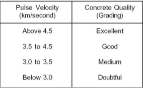
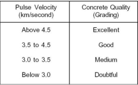
- The nice of concrete in phrases of uniformity, occurrence or absence of inner flaws, cracks and segregation, etc, Indicative of the extent of expertise employed, can as a consequence be assessed the use of the recommendations given below, that have been advanced for characterizing the nice of concrete in systems in phrases of the ultrasonic pulse pace.
|
Fig no Table of pulse velocity
Key take ways
2. Set reference: A reference bar is supplied to test the tool zero. The pulse time for the bar is engraved on it. Apply a smear of grease to the transducer faces earlier than putting it on the other ends of the bar. Adjust the ‘SET REF’ manage till the reference bar transit time is acquired at the tool read-out.
PULLOUT TEST
The principle
This test is based on the principle that the force required to extract a metal coating embedded in concrete is equal to the strength of the concrete.
Test Process
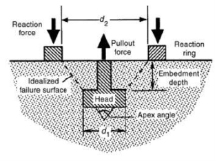
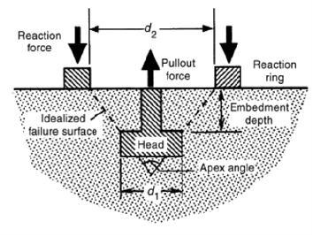
Remove the insert (shown on the fig tree) embedded in the empty concrete during pouring. When power is required to be determined, power is applied to the embedded end. The power required to issue a meeting is measured.
|
Fig no Pull out the concrete test
Limitations
The steel assembly should be embedded in concrete at the time of pouring so testing may not be carried out in the years to come.
Damage to damaged concrete is required.
Evaluation
- The extraction assembly is pulled by a concrete cone, which is responsible for friction and shaving and the force required to exit is related to the cutting strength of the concrete and not the compressive force.
- The rate of dissipation in the compression force decreases slightly with increasing power level.
- Removal cannot be performed until complete. It is sufficient to insert a fixed power into the embedded pole and if not removed, the supplied power is assumed to exist.
- According to Malhotra, the output test is higher than the Schmidt hammer and the input test because a large volume and depth of concrete are involved in the test. Post-test concrete repairs are also required. The relationship between the force of gravity and gravity is shown in the figure below.
IMPACT ECHO TEST
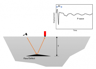
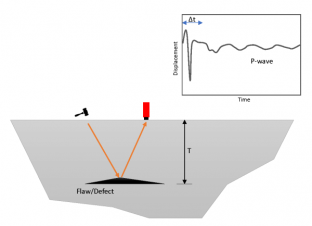
Impact-Echo is a non-destructive exploration method for exploring concrete structures and stone structures. The test uses pressure waves (sound) that are usually made of impact-impact concrete, and to record thinking and emissions from internal errors and other parameters (Echo). Typically, a heartbeat is performed with an effect in one place. The resulting wave of depression is spreading in all directions. In this regard, the generated wave does not have a directional pulse generated by a large transducer (as in the case of ULTRASONIC PULSE VELOCITY). As the reflection reaches in all directions, the test method works well for thin objects, such as piles where the outer boundary directs the wave to the pile. In this particular application, the test is set as the low-level strength test. Learn more about the PILE INTEGRITY TEST.
Concept Behind Impact-Echo Method
The concept of Impact-Echo testing is shown in Figure. The mechanical impact of the concrete surface is used to produce a pressure wave. The production pulse creates a spread across the concrete next to circular waves such as P- and S-waves. Another is the surface wave (R) that moves over.
|
Fig no Impact echo method
As the P- and S waves propagate inside the concrete object, they are indicated by internal interactions (concrete-split, air-concrete, concrete -rebar) or external boundaries. The arrival of these echo in the face causes migration. This migration can be measured by placing a sensitive transducer (which converts the transmission or acceleration of electrical energy). Data is recorded through a data acquisition and data entry system.
Analyzes Impact-Echo data
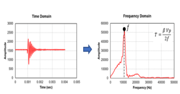
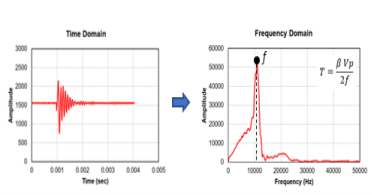
Data analysis can be done in Time Domain, or Frequency Domain. While time domain analysis seems to be the best way to define sensitive data (as in the case of bulk testing), it can be a much more complex approach in the case of small slabs .In these sections, signal analysis in the domain of frequency is popular.
|
Fig no Analysis of impact echo method
The Fast Fourier transform (FFT) process is used to analyze digital frequency frequency recordings. In this way, the wave form can be represented as a total of sine curves, each with a certain height, frequency and phase shift. According to N. J. Carino .This method is used to calculate the amplitude magnitude of a frequency form, which gives the relative height of the fractional frequencies in the wave form.
Impact-Echo Technique Applications
Impact-Echo is an effective test solution with a variety of applications in assessing the condition of concrete structures. The test can be used to:
1- Measure the thickness of the concrete labs and walls
2- Measure the thickness of the concrete walls and the tunnel line
3- Identify deformities such as delamination in concrete books.
4- Measure the storage condition of concrete, dams, tunnel lamps, sea walls.
Key takeaways
- This test is based on the principle that the force required to extract a metal coating embedded in concrete is equal to the strength of the concrete.
- Impact-Echo is a non-destructive exploration method for exploring concrete structures and stone structures. The test uses pressure waves (sound) that are usually made of impact-impact concrete, and to record thinking and emissions from internal errors and other parameters (Echo).
References
1. Concrete Technology by M L Gambhir, Tata McGraw Hill. 3. Concrete technology by A. M. Neville. 1. Brooks, Pearson,
2. Microstructure and Properties of Conctete by P. Kumar Mehta, Prentice Hall.
3. Durability Design of Concrete Structures, by A. Sarja and E. Vesiari. E & FN Spon Publication, 1996.
