Back to Study material
GE

Unit - 1

Introduction and Index Properties


  • According to Dr. Terzaghi (1948) 'Soil mechanics or Geotechnique is the application of laws of mechanics and hydraulics to engineering problems dealing with sediments and other unconsolidated accumulations of solid particles produced by the mechanical and chemical disintegration of rocks regardless of whether or not they contain an admixture of organic constituents.
  • Thus, one can say that soil mechanics or geotechnique is a branch of civil engineering that deals with application of principles of mechanics, hydraulics, chemistry to engineering problems related to soil. For example, in foundation, the structure ultimately rests on soil and the bearing capacity of the soil plays an important part of foundation design and knowledge is also useful in construction of earth dams, ground water movement, seepage, slope stability, bank protection, well hydraulics etc.
  • Geotechnical engineering is a new term which includes soil mechanics, soil engineering, rock mechanics and rock engineering.
  • One can say geotechnical engineering is one which encompasses not only mechanics or geotechnique but also soll dynamics, part of structural engineering and many other disciplines which are frequently essential to obtain practical solution to problems of soils.
  • Key Takeaways:

    Geotechnique is the application of laws of mechanics and hydraulics to engineering problems dealing with sediments and other unconsolidated accumulations of solid particles produced by the mechanical and chemical disintegration of rocks regardless of whether or not they contain an admixture of organic constituents.


  • In order to solve following problems in civil engineering, the knowledge of geotechnical ring is of importance.
  • Thus, various applications of geo-technical engineering are as follows:
  • Foundation design
  • Pavement design
  • Design of earth dam
  • Earth retaining structure
  • Design of embankments
  • Design of underground structures
  • 1. Foundation design:

  • Bearing capacity is one of the most important property considered in foundation design as foundation is important element of all civil engineering structures
  • The area of the foundation will depend upon bearing capacity of soil. If we increase area of foundation, the intensity of load i.e., compressive stress is within limit of the bearing capacity. is the foundation will be safe and problem of settlement is solved.
  • For every structure, building, bridge: highway, dam etc. Soil is ultimate foundation material which support any structure and proper functioning of any structure.
  • Thus, one can say life of structure depends upon the foundation strong will be the foundation more will be the life of structure.
  • So, it is therefore, necessary to have sound knowledge of soil, i.e., bearing capacity of soil, the pattern of stress distribution in the soil beneath the loaded area, the probable settlement of the foundation, effect of ground water and effect of vibration also its shrinkage and swelling etc.
  • 2. Pavement Design:

  • A pavement may be of any type rigid or flexilie, its performance depends upon the subsoil on which it rests.
  • The thickness of pavement depends upon certain properties of sub soil, which should be determined before the design is made.
  • Also, while designing the pavement various points related with soil like frost, heave a thaw with their related problems of frost damage to pavements, frost penetration depth, remedial measures to prevent it, problem of pumping and suitability of soil as a construction material for constructing highways, railways etc should be decided.
  • 3. Design of Earth Dam

  • Soil is the only material required for the construction of earth dam thus thorough knowledge of soil mechanics is required.
  • Since various types of soil is used in the construction of the carth dam, it is necessary to determine the soils properties, index properties such density, plasticity characteristics and specific gravity, particle size distribution and gradation of the soil, permeability, consolidation and compaction characteristics and shear strength parameter under various drainage condition.
  • 4. Earth Retaining Structure:

  • The example of earth retaining strictures are gravity retaining wall, anchored bulk heads and cofferdams.
  • The active and passive earth pressures and the safe critical heights of an open cut form the important properties in the design of earth retaining wall.
  • Permeability of the soil retained behind the wall is also important for the drainage of the retained earth.
  • Thus, knowledge of soil structure interaction is essential to design properly the retaining structures subjected to soil loadings.
  • 5. Design of Embankments:

  • A thorough knowledge of shear-strength and related properties of soil is essential to design the slope and height of the embankment and cutting.
  • The shear strength of soil reduces due to the seepage of water, thas while excavating this factor must be taken into account.
  • Thus, knowledge of soil mechanics is important in design of embankments and excavation to face above situation and problems like seepage, caving in etc and also action to increase the soil strength and to reduce the seepage forces, action to drain the subsoil water etc.
  • 6. Design of Underground Structures:

  • The examples of underground structures include tunnels, underground buildings, drainage structures and pipelines.
  • Thus, for design of such structure a thorough knowledge of soil structure interaction is essential as such structures are subjected to sail loading.
  • Also, one must have knowledge of stearing strength, angle of repose and frictional coefficient is essential and to solve problem such as seepage, caving in etc and also to improve the properties of soil to increase shear strength and reduce seepage.
  • Thus, from above examples it is clear that the soil mechanics is important in various field of construction.
  • Key Takeaways:

    Thus, various applications of geo-technical engineering are as follows:

  • Foundation design
  • Pavement design
  • Design of earth dam
  • Earth retaining structure
  • Design of embankments
  • Design of underground structures

  • Soil structure is the geometrical arrangement of soil particles with each other.
  • Properties of soil such as permeability compressibility, shear strength etc is greatly affected by soil structure.
  • The following types of soil structure are generally recognized
  • Single grained structure
  • Honeycomb structure
  • Flocculent structure
  • Dispersed structure
  • Composite structure
  • 1. Single grained structure:

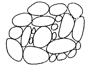
  • When each panicle of soil seciles out of suspension separately and independently then such soil structure is known as single grained structure.
  • The gravitational forces acting on the particles of soil cases the settlement.
  • The specific surface of all particles is comparatively less, thus the surface forces are too small to be considered.
  • These surface forces are neglected for all practical purpose in case of course grained soils (Diameter> 0.02 m).
  • Such soil particle has high void ratio when the deposite in a loose state and low void ration in a dense state.
  •  

    H:\unit1\IMG_20210519_204025.jpg

    Fig.1.1: Single grained structure

    2. Honeycomb structure:
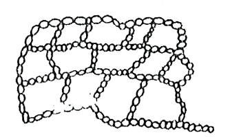
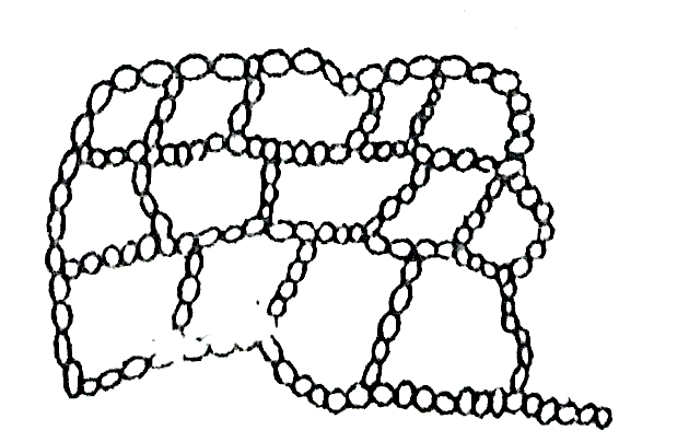
  • Honeycomb structure is seen in the soil particles having diameter between 0.0002-0.02 mm, usually observed in silts.
  • In case of such soils, both gravitational forces and surface forces plays an important role.
  • The soil particles settle due to gravitational forces and the surface forces at the contact area, are large enough compared to the submerged weighs to prevent the grains from rolling down immediately.
  • The grains which are in contact are beld together until miniature arches are formed, with relatively large void space which is formed as honeycomb structure.
  • In such type of structure comparatively large amount of water is enclosed within voids.
  • Such type of structure has high voids ratio.
  • H:\unit1\IMG_20210519_204045.jpg

    Fig.1.2: Honeycomb structure

    3. Flocculent structure:
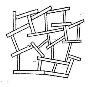
  • Flocculent structure is formed when there is an edge contact between the clay platelets.
  • The attractive electrical forces between adjacent soil particles at the time of deposition, is the basic reason for the formation of such type of structure.
  • As the concentration of dissolved minerals is the water increases, the tendency of flocculation also increases.
  • Flocculent structures are usually observed in clays with fine particles.
  • H:\unit1\IMG_20210519_204118.jpg

    Fig.1.3: Flocculent structure

    4. Dispersed structure:
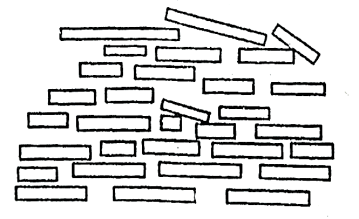
  • Dispersed structure is also seen in clays with fine particles.
  • The repulsion electrical forces between adjacent soil particles at the time of deposition are responsible to form dispersed structure.
  • H:\unit1\IMG_20210519_204139.jpg

    Fig.1.4: Dispersed structure

    5. Composite Soil Structure:

  • In case of composite soil following two structures can be found,
  • Coarse grain skeleton
  • Cohesive matris
  • 1.Coarse grain skeleton:

  • When the void space between the single particles is filled with the clay particles; it is called as coarse grain skeleton.
  • The bulky particles form a continuous relatively incompressible frame-work.
  • 2.Cohesive matrix:

  • When the clay content is more as compared with coatse particles; cohesive matrix is formed.
  • Such type of soil formation is relatively more compressible.
  • Key Takeaways:

    The following types of soil structure are generally recognized

  • Single grained structure
  • Honeycomb structure
  • Flocculent structure
  • Dispersed structure
  • Composite structure

  • On the bases of climatic conditions, topography and geology of their formation, major soil deposits of the India can be broadly divided into the following groups,

  • Marin deposits
  • Black cotton soils
  • Laterites and lateritic soils
  • Desert soils
  • Boulder deposits
  • Alluvial soil deposits
  • 1. Marine deposits:

  • Usually along the coast in narrow tidal plains marine clays are found.
  • Marine clay may contain organic matter and also very soft clay.
  • Marine clay has low shear strength and high compressibility.
  • Because of above properties, such clay has problems to be used as construction material or as a foundation material.
  • 2. Black cotton soil:

  • Black cotton soils are usually found in Maharashtra, Madhya Pradesh, Karnataka, Andhra Pradesh, Tamil Nada and Uttar Pradesh.
  • Black cotton soil (Indian name) is also known as Expansive soils.
  • In India they cover an area of approximately 3,00,500 Sq. Km.
  • This soil is formed from basalt or trap.
  • Black cotton soil is characterized by swelling and shrinkage because it contains clay mineral montmorillonite.
  • As the volume of black cotton soil changes it is most susceptible to damage the light loaded structure.
  • Under-reamed piles are considered most suitable as foundations for houses and other light structures constructed en such soil.
  • These piles are taken to depths below the zone of seasonal variation in moisture content.
  • 3. Laterites and lateritic soil

  • These soils are usually found in Kerala, Karnataka, Maharashtra, Orissa and west Bengal.
  • In India they cover an area of about 100,000 Sq. Km.
  • The decomposition of rock, removal of the bases and silica and formation of oxides of iron and aluminium at the top of the soil profile are responsible for formation of laterites.
  • Like all residual soils, laterites show variability in their properties, depending upon the stage of weathering.
  • 4. Alluvial deposits

  • Alluvial soils are formed in large parts of Northen India lying North of vindhya satpura range in the Indo-Gangetic and Brahmaputra flood plains.
  • The alluvial deposits extend from Assam in the East to Punjab in the west.
  • The deposits have alternating layers of sand, siht and clay.
  • 5. Desert soils

  • Such soils are found in large parts of Rajasthan.
  • They cover an area of about 500,000 sq.m.
  • They are formed under highly arid conditions.
  • Dune sand is a non-plastic uniformly graded, fine sand.
  • Some of the problems associated with this soil are stabilization, settlement perviousness etc.
  • 6. Boulder deposits

  • Boulder deposits are found in the sub-Himalayan regions of Himachal Pradesh and Uttar Pradesh.
  • River flowing in hilly terrains and near foot hills are responsible to deposit large quantities of boulders.
  • The properties of these deposits depend on the relative proportions of the boulders and the soil matrix.
  • These deposits have higher angles of shearing resistance.
  • Key Takeaways:

    On the bases of climatic conditions, topography and geology of their formation, major soil deposits of the India can be broadly divided into the following groups,

  • Marin deposits
  • Black cotton soils
  • Laterites and lateritic soils
  • Desert soils
  • Boulder deposits
  • Alluvial soil deposits

  • Many times, laboratory tests are neither feasible nor practicable
  • At such instances, if a name tag can be put to a soil, a knowledgeable soil engineer will be able to gain much data from simply identifying the oil type.
  • Field tests and field identification is thus a great tool in soil engineering.
  • The soils to be identified in field may be coarse grained soil or fine-grained soil.
  • 1.Coarse Grained Soil:

  • On the field coarse grained soils are identified by visual inspection and must be described on the bases of grading, grain-shape, colour, in-situ strength, structural features and presence of fines etc.
  • Grading:

  • By visual inspection one can judge the coarse grain soil by its grading and can classify soil as well-graded, uniformly graded or poorly graded.
  • Grain shape:

  • Grains can be defined on the field based on their shape, usually term used to describe the grain shape are angular, sub-angular and rounded.
  • Colour:

  • Based on the colour of soil at field, soil can be expressed as white, yellow, brown, red brown etc.
  • Strength and structure:

  • The term compact and loose are used to determine in-situ strength of deposit of coarse-grained soil.
  • The structure of coarse-grained soils recognized in the field can be described as homogeneous or stratified.
  • Presence of fines:

  • If soil contains some organic matter; it should be indicated.
  • If it has some fines, and not causing cohesion, it should also be noted.
  • 2. Fine Grained Soil:

  • Following test are carried out for identification of fine-grained soil.
  • For this, the soil is sieved on site through 425-micron sieve and the fraction passing through is taken for the tests.
  • Dry strength test:

  • The prepared sample is completely dried in sun or by air drying. Its strength is tested by breaking lump between fingers
  • Resistance to breaking, termed as dry strength is a measure of the plasticity and is considerably influenced by the colloidal fraction content of the soil.
  • If the dry sample can be easily powdered it is said to have low dry strength, thus indicates silt or sandy silt.
  • If considerable finger pressure is required to break the lump, it has medinm dry strength, thus indicates silty clays and clays of low plasticity.
  • If the lump cannot be powered by fingers at all, it has a high dry strength which represents a lightly plastic clay.
  • The presence of water-soluble cementing materials, such as calcium carbonate or iron oxides, may also cause high dry strength.
  • Soil with high strength is treated with a little line bydrochloric acid. A stroug reaction indicates that the strength may be due lo calcium carbonate as cementing agent rather than colloidal clay.
  • Dilatancy Test:

  • Dilatancy means reaction to shaking About 5CC soil sample is taken and enough water is added to nearly saturate it.
  • The pat of soil is placed in the open palm of the hand and shaken horizontally be striking vigorocesly against the other hand several times.
  • The pat is then squeezed between the fingers.
  • The appearance and disappearance of water with shaking and squeezing is called a positive reaction. This reaction is called quick if water appears and disappears slowly and no reaction if water condition does not appear to change.
  • The type of reaction is observed and recorded. Inorganic sits show a quick reaction where as clays show no reaction or slow reaction
  • Toughness Test:

  • The soil sample used in dilatency test is dried by working and moulding till it reaches the consistency of putty.
  • The time required to dry the sample is indicative of its plasticity. Further, the moisture content is reduced by rolling and re-tolling the soil into a thread of 3 mm diameter till it reaches the plastic limit.
  • The resistance to moulding at plastic limit is called the toughness. After the thread crumbles, the pieces are lumped together and the slight kneading action is continued until the lump also crumbles.
  • If the lump can still be moulded slightly drier than plastic limit and if high pressure is required to roll the thread between the palms of the hand, the soil is said to have high toughness.
  • Medium toughness is indicated by medium thread and a lump formed of the threads slightly below the plastic limit will crumble.
  • While low toughness is indicated by a weak thread that breaks casily and cannot be dumped together when drier than plastic limit.
  • Non-plastic soils cannot be rolled into 3 mun diameter threads at any water content.
  • Organic silt or clay:

  • If the amount of organic matter is small it is difficult to identify.
  • Organic soil has a distinctive odour when fresh and wet.
  • By heating the wet soil sample, odour can be made more noticeable.
  • Fibrous organic soils, such as muck or peat, are dark brown to black in colour with distinctive odour.
  • Other identification tests:

  • High plasticity is indicated on the field, if we cut the dry o: slightly moist lump of soil with a knife blade, it produces a shiny soil surface. A dull surface indicates clay or silt of low plasticity.
  • Silt sticks to fingers will wash away easily and brush off, if dry, whereas wet clay sticks to the fingers, gives a greasy feel and does not was easily.
  • In soil suspension of water of about 10 cm depth.
  • Clay-size particles will remain in suspension for several hours or even days.
  • Within 5 to 60 minutes silt will settle.
  • Whereas sand will settle easily with is half a minute.
  • Key Takeaways:

    Field tests and field identification is thus a great tool in soil engineering. The soils to be identified in field may be coarse grained soil or fine-grained soil.


  • The soil exploration is technical investigation by which the necessary information regarding various soil properties are obtained which helps in designing safe and economical construction it called soil exploration.
  • The purpose of soil exploration is to find out the nature and dimension of underlying soils. It also tells whether soil is gravel, sand, clay, silt etc. It also helps in indicating depth and thickness of soil layer.

  • Site investigation and subsoil explorations are necessary for following purpose:
  • For finding index properties
  • To determine bearing capacity for foundation design
  • To know stratification
  • For seepage control
  • For treating problem soils
  • For enhancing properties by compaction and stabilization.
  • 1. For finding Index properties:

  • Index properties such as bulk density, specific gravity, void ratio, porosity, water content, degree of saturation etc.
  • These properties affect the other mere complex properties such as permeability, shear strength, compressibility, bearing capacity etc.
  • Hence index properties form the important basic step of investigation.
  • Most of the index properties are determined in the laboratory, but sometimes field tests are also deemed to be important.
  • For collecting the samples for determination of index properties, the site investigation and subsoil exploration is thus found to be necessary.
  • 2. To determine bearing capacity for foundation design:

  • This is the most preliminary purpose of soil investigation.
  • Bearing capacity goes on increasing with depth in most soils.
  • As we go deeper and deeper, we encounter soil with more and more bearing strength.
  • The bearing strength required for a particular structure must be available.
  • Thus, the bearing capacity is estimated at a particular depth and then it can be actually tested by various tests available, of which plate load test is an important one.
  • Thus, the site investigations are very important for determining the bearing capacity of soil.
  • 3. To know stratification:

  • Soil contains different layers or strata below the surface and are arranged in different ways.
  • The strata may be continuous, displaced by a crack or fault, at different angles, separated by a dyke arranged in the form of folds etc.
  • The arrangement of strata helow the ground level is called stratification.
  • The properties of the soil like permeability or bearing capacity depend on the orientation and nature of the stratification.
  • When we take horeholes at the foundation level, or when we dig bore holes or test-pits, this arrangement is clearly visible by the side of the bore holes or test-pits.
  • Thus, by taking numerous boreholes, a geological map of the underground strata can be prepared.
  • This will give a complete idea of the stratification of soil.
  • Thus, investigations enable us to find the hidden features below the ground level.
  • 4. For seepage control:

  • Seepage is important in case of earth danis, wears and aprons on permeable foundation.
  • Soil which has same permeability in y direction i.e., in gravitational direction, and in x direction i.e direction perpendicular to gravity is called isotropic soil.
  • Soil which has different coefficients of permeability Kx and Ky is called anisotropic soil.
  • The net effect can be considered as a two-dimensional flow which can be analysed by Laplace equation and flow-net technique. The effective flow will be the seepage flow.
  • During detailed investigation of soil and subsoil, field tests will give realistic picture reinforced by laboratory tests conducted on soil samples, both disturbed and undisturbed, obtained from sub-soil explorations.
  • Thus, for seepage control, the detailed investigations will give a fair basis for further analysis.
  • 5. For treating problem soils:

  • Problem soils are those which have uncommon behaviour when confronted with various parameters whether natural or artificial. Mainly two conditions come under this category
  • (a) The quick sand condition

  • When water seeps through sand and comes to the surface, the head with which it comes out of the surface is called the exit gradient.
  • Due to large increase in exist gradient, more than the critical gradient, effective submerged weight of sand may become zero due to upward force of seepage.
  • Thus, de sand comes to the surface continuously and appears to boil. This condition called the quick sand condition and if it occurs below foundations, it will be dangerous.
  • (b) The black cotton soil

  • This soil is not weak in bearing capacity, nor it is excessively permeable.
  • The problem in black cotton soil is the disproportionate volume change which occurs upon change in moisture content.
  • This soil swells to a very high degree, even upto double the original volume upon double the original volume upon being saturated with moisture and shrinks equally largely when it loses the moisture.
  • It may become even upto half its saturated volume when dried completely. Due to this property, the foundations resting on this type of soil will be subjected to large alternate movements during rainy season and summer.
  • Hence special remedial measures must be taken when it is inevitable to build foundations on black cotton soil.
  • Thus, brings out the necessity of soil and subsoil investigations.
  • 6. For enhancing properties by compaction and stabilization:

  • Simplest method of soil stabilization is compaction. The term stabilization is generally used when compaction is enhanced by some other method or when it is enhanced by adding some substance as an admixture.
  • In any case, he its compaction or stabilization, the properties of soil such as maximum dry density (MDD), Optimum Moisture Content (OMC), permeability, drainage characteristic etc. must be determined to a fine degree.
  • Doing such an investigation it will achieve much desired effects to a large extent within the least expense.
  • Even the decision of whether to go for compaction or not, whether simple compaction or stabilization is required etc. depend on investigations of soil and subsoil carried out in details to a meticulous degree of perfection.
  • Key Takeaways:

    Site investigation and subsoil explorations are necessary for following purpose:

  • For finding index properties
  • To determine bearing capacity for foundation design
  • To know stratification
  • For seepage control
  • For treating problem soils
  • For enhancing properties by compaction and stabilization.

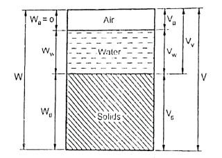
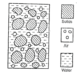
  • The soil mass in general is a three-phase system composed of soil, liquid and gaseous matter. The solid phase comprises of mineral, organic matter or both.
  • The mineral portion consists of particles of different size and shapes.
  • The organic fraction is the plant and animal residue which may be present in various stages of decomposition.
  • The solids enclose the open spaces termed as voids. The liquid phase is generally water and fills partly or wholly the voids.
  • The gaseous phase, usually air, occupies the voids not filled by water. The relative volume wise and weight wise proportions of the three phases in a soil mass are important factors influencing its physical properties.
  • It is therefore necessary to study them. Though the three phases prescut can not be separated as shown in below Fig. for better understanding they are shown as occupying separate spaces.
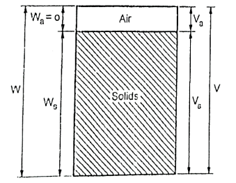
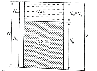
  • The diagrammatic representation of the different phase present in a soil mass is called the phase diagram.
  • Fig. shows a three-phase system of natural soil which is partially saturated soil.
  • When it is fully saturated i.e., all the voids are filled with water and thus gaseous phase is absent and the soil becomes a two-phase system in fig.
  • H:\unit1\IMG_20210519_204205.jpg

    Fig.1.5: Natural soil

    H:\unit1\IMG_20210519_204224.jpg

    Fig.1.6: Partially saturated soil

    H:\unit1\IMG_20210519_204248.jpg

    Fig.1.7: Dry condition

    H:\unit1\IMG_20210519_204328.jpg

    Fig.1.8: Saturated condition

  • Also, if the soil becomes totally dry and consists of only solid and gaseous phases. In this case also it is a two-phase system.
  • Ww=Weight of water

    Ws =weight of soils

    V =total volume of soil mass

    Va =volume of air

    Vw =volume of water

    Vv =volume of voids

    Vs =volume of solids

  • For Partially Saturated Condition,
  • Total weight, W=Ws+Ww+Wa

     Wa=0

    W=Ws+Ww

    Total volume, V= Vs+Vv= Vs+Va+Vw (3 phase system)

  • For dry condition,
  • W=Ws

    V=Vs+Va (2 phase)

  • For fully saturated soil,
  • W=Ws+Ww

    V=Vs+Vw (2 phase)

    Key Takeaways:

    The soil mass in general is a three-phase system composed of soil, liquid and gaseous matter. The solid phase comprises of mineral, organic matter or both. The mineral portion consists of particles of different size and shapes. The organic fraction is the plant and animal residue which may be present in various stages of decomposition.


  • The physical properties of soil which are useful to identify and distinguish soils from one another are called as index properties.
  • The main index properties are: Particle size distribution, density index, consistency etc.
  • The index property gives some information about the engineering properties.
  • The index properties are sometimes divided into two:
  •        1) Properties of soil mass

           2) The properties of individual particle size.

    1) Properties of soil mass:

  • This property depends upon;
  • The mode of soil formation.
  • Soil history
  • Soil structure.
  • Such properties are usually determined by undistruibed samples or preferably from in-situ tests.
  • 2) The properties of individual particle size:

  • This property depends upon does not individual grains and depend on the mode of soil formation.
  • Such properties are usually determined by distruibed samples.
  • Key Takeaways:

    The main index properties are: Particle size distribution, density index, consistency etc. The index property gives some information about the engineering properties.


    Water Content Determination:

    Following methods are used to find the water content

  • Oven drying method.
  • Calcium carbide method.
  • Infrared torsion balance method.
  • Sand bath method
  • Radition method.
  • Alcohol method
  • Pycnometer method.
  • 1) Oven drying method

  • Determination of water content by oven-drying method as per IS code 1S-2809-1972
  • This is the commonly adopted and simplest method for determination of water content of a soil sample in the laboratory.
  • The method basically consists of drying a weighed moist sample of soil, in an oven at a controlled temperature for a period of 24 hours, after which the dry weight of the sample is taken.
  • The drying of soil is recommended at a temperature of 105°C 110°C as temperatures M higher than 110°C may break the crystalline structure of clay particles result in loss of water of crystallization thus giving wrong results.
  • A lower temperature of 60° is recommended for highly organic soils as at 110°C, oxidation of organic matter may take place.
  • Sand and gravels require less time to dry i.e., 4 to 6 hours but routine laboratory procedure is fo. drying for 24 hours at 105°C-110°C.
  • A clean, non-corrodibile container is weighed within 0.01 gm accuracy. About 30-40 gm of moist soil sample is placed in it and weighed accurately.
  • It is then placed in the oven for drying at 110°C for 24 hours.
  • 2 )Calcium carbide method

  • This method can be used in both field as well as in laboratory.
  • The method makes use of fact that when water reacts with calcium carbide (CaC2)
  • acetylene gas (C2H2) is generated.
  • CaC2+2H2O=C2H2+Ca (OH)2
  • Pressure is exerted by acetylene gas produced.
  • The instrument used in this method is rapid moisture tester.
  • The dial gauge attached to the moisture tester is used to measure this pressure.
  • The soil sample of 6 grams is taken in the test cylinder containing calcium carbide.
  • The soil sample is required to be ground and pulverized.
  • The steel halls are also used to serve the purpose in case of cohesive and plastic soils.
  • The quantity of gas produced is indicated on the dial gauge in terms of pressure. From calibrated scale of pressure gauge the moisture content (m) based on total mass is determined.
  • The water content (w) based on dry mass is calculated as,
  • W =

    W= x 100 %

    Determination of Consistency limit:

    Determination of Liquid Limit:

    Following are the two Methods used for the Determination of Liquid Limit in the Laboratory

  • By Casagrande's method
  • By Cone penetrometer
  • By Casagrande's method (IS 2720 part 5-1985):
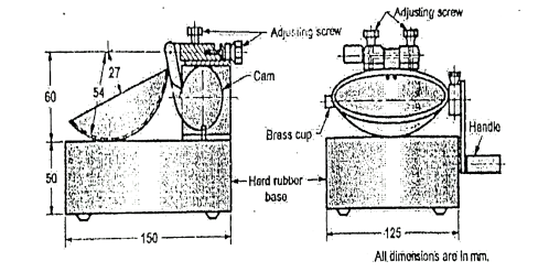
  • In the laboratory, standard apparatus knows as casagrande's apparatus, along with the standard tools is used to determine the liquid limit.
  • It consists of a brass'cup mounted on a hard rubber base. The cup can be raised and made to fall on the hard rubber base.
  • The distance of the fall can be regulated by screws.
  • The fall is made 1 cm before the start of the test.
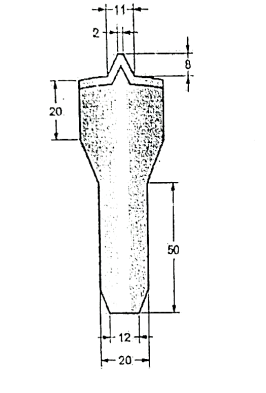
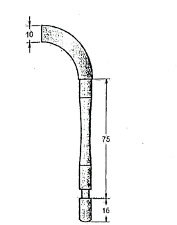
  • There are two types of grooving tools as shown in the Fig. 1.22.1, to be used for different types of soils. For more sandy soils, ASTM tool is used and for claye soils, casagrande tool or spatula is used.
  • About 120 grams of air-dried soil passing through IS sieve of 425 micron is taken and mixed with water such that the soil attains a putty like consistency.
  • A portion of the paste is placed in the cup and is levelled so as to have a maximum depth of 1 cm
  • A groove is cut in the soil placed in the cup and is levelled so as to have a maximum depth of 1 cm.
  • A groove is cut in the soil placed in the cup by using appropriate grooving tool.
  • In cutting the groove, the tool is drawn through the sample along the symmetrical axis of the cop, holding the tool perpendicular to the cup
  • The handle is rotated at the rate of 2 revolutions per second and the number of blows required to close the groove for a distance of 1.25 cm is noted.
  • The groove should close by flow and not by slippage of soil.
  • Then about 10 gm of soil near the groove is taken to determine its water content. By altering the water content of the soil and repeating the procedure 4 to 5 readings of water content in the range to 10 to 40 blows are obtained.
  • A graph is then plotted between number of blows on a logarithmic scale water content on a natural scale as shown in Fig.
  • H:\unit1\IMG_20210519_204446.jpg

    Fig.1.9: Liquid limit apparatus

    H:\unit1\IMG_20210519_204515.jpg

    Fig.1.10: Casagrande tool

    H:\unit1\IMG_20210519_204551.jpg

    Fig.1.11: ASTM tool


  • It will be seen that the semi-logarithmic plot is a straight line whose equation is
  • W-W = If

    Where w1xw2, are the water contents corresponding to blows N1 and N2. If is the slope of line and it is called the flow index. The line is called the flow curve.

  • The liquid limit is then determined by reading the water content corresponding to 25 blows, on the flow curve.
  • Determination of Plastic Limit: (IS-2720 part 5-1985)
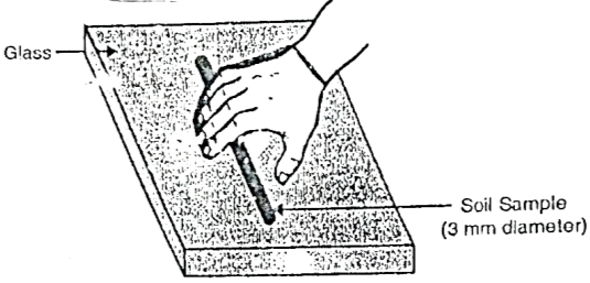
  • In order to determine the plastic limit about 15 gm of air-dried soil sample passing through IS sieve 425 u is taken and is mixed with a sufficient quantity of water which would enable the soil mass to become plastic enough to be easily shaped into a ball.
  • A portion of the ball is taken and rolled on a glass plate with the palm of the hand into a thread of uniform diameter. When a diameter of 3 mmn is reached, the soil is remoulded into a ball. The process of making the thread and remoulding is continued till the sample at a diameter of 3 mm just start crumbling.
  • Some of the crumbled pieces are then taken for water content determination by oven drying method.
  • The test is repeated twice more with fresh samples and the average of the three values is taken as the plastic limit.
  • A steel rod of 3 nun diameter kept by the side of the glass plate helps in comparing the thread diameter easily.
  • H:\unit1\IMG_20210519_220555.jpg

    Fig.1.12: Plastic limit determination
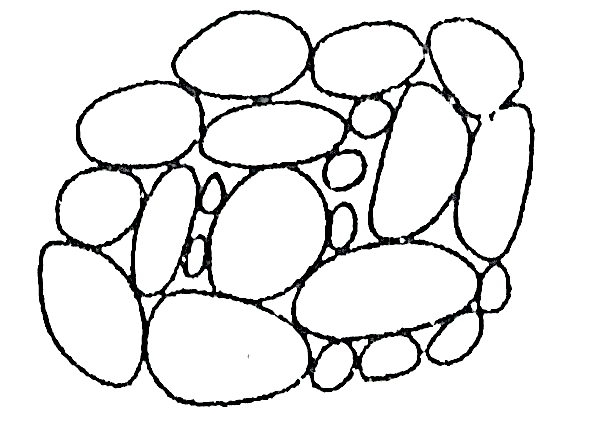
    Fig.1.13: Plastic limit determination

    Determination of Shrinkage Limit: IS-2720, Part 6-1972 Reaffirmed 1975
  • About 30 gms of soil sample passing 425-micron sieve is taken in an evaporating disk.
  • The soil is mixed with sufficient quantity of water to bring the soil to a consistency that it may flow.
  • The soil mixture is placed in the shrinkage dish in three equal quantities so as to fill the dish. The excess soil is removed and the dish is weighed with the soil.
  • The soil pat is allowed to dry till the colour changes from dark to light.
  • The dish is placed in the oven at 110°C till its weight become constant.
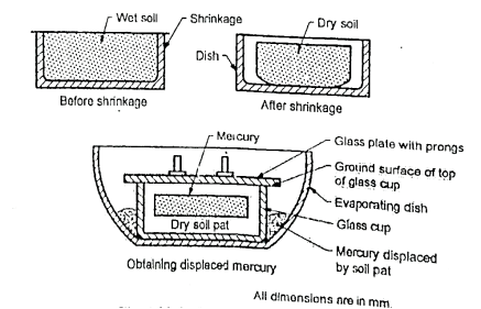
  • The shrinkage dish is weighed with dry sample and the volume of dry pat of soil is measured displacement of mercury.
  • The shrinkage limit is calculated as shown in Fig.
  • Fig.shows the arrangement for shrinkage limit test.
  • Fig.shows the phase diagrams.
  • Fig represents the soil sample in plastic state which fill the container of know volume V1 and weighs w1. As the sample is gradually dried, the water content at a certain stage becomes equal to the shrinkage limits as in Fig.
  • Fig.1.14: Shrinkage limit apparatus


    H:\unit1\IMG_20210519_220658.jpg

    Fig.1.15: Shrinkage limit apparatus

  • At this point the volume is decreased to V, the corresponding perfectly saturated state.
  • Beyond shrinkage limit, sample continues to dry and its weight continues to reduce. But its volume remains V, as now the decrease in weight is due to loss of water from the voids.
  • When there is no further loss in weight, the sample is completely dry and its weight is w, while volume is V2, as weight of air is negligible.
  • The shrinkage limit is the water content at situation of Fig.
  • Ws =
    ×100
  • Thus, by measuring the starting weight and volume and the dry weight and volume, shrinkage limit ws can be calculated. Here
    is the 1imit weight of water.
  • Determination of Unit Weight:

    Following methods are generally used to determine the field density of soils

  • Core cutter method.
  • Sand replacement method.
  • Water displacement method.
  • Core cutter method

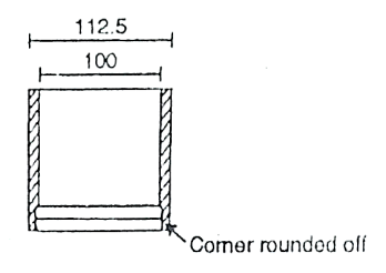
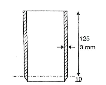
  • The core cutter method consists of driving a core cutter of known volume usually 1000 CC into the soil after placing it on cleaned soil surface.
  • The core cutter is usually provided with 125 mm high dolly.
  • The driving of core cutter is accomplished by hitting the dolly mounted on the core cutter with the rammer.
  • The cutter filled with the soil is removed by cutting under it with a knife or sharp edge. The extra soil is trimmed off. The cutter with the soil is weighed.
  • The volume of the core cutter is calculated from the inner dimensions. The weight of empty core-cutter is also taken. Then the insitu unit weight is determined by dividing the weight of soil in the core-cutter by the volume of the core-cutter.
  • For determining the dry unit weight, a piece of the soil is taken and its water content determined by oven drying method.
  • Then the dry density can be found from the bulk density as follow:
  • Bulk density
    =mass of wet soil / volume of core cutter
  • ρ= (g/cm3)

    Bulk unit weight, r= 9.81 ρ kN/m

    Where w=water content

    The core-cutter is shown in Fig.
    H:\unit1\IMG_20210519_220721.jpg

    Fig.1.16: Core cutter

    H:\unit1\IMG_20210519_220742.jpg

    Fig.1.17: Dolly

    H:\unit1\IMG_20210519_220806.jpg

    Fig.1.18: Rammer

    Procedure:

  • Measure inside dimension of core cutter and calculate volume.
  • Find the mass of the core cutter (without a dolly).
  • Clean top of soil on site and level it places dolly on top of the core cutter and drive into the soil with help and rammer until about 1 to 1.5 cm of dolly remain above surface.
  • Dig out container which is containing soil from ground. Remove dolly with help of straight edge trim flat and the end of cutter.
  • Find mass of cutter fall with soil and find out water content (w2).
  • Repeat procedure 2 to 3 locations nearby and get average dry density.
  • Key Takeaways:

  • Water Content Determination
  • Determination of Unit Weight
  • Determination of Consistency limit

  • The unified classification is based on the airfield classification system that was developed by A. Casagrande
  • The system is based on both grain size and plasticity properties of the soil and is therefore, applicable to any use.
  • The Indian Standard Institution (now Bureau of Indian Standarde) adopted the unified classified system in 1954. The soil classification system 15 1498: 1970 is generally except for mine modification. Hence the salient features of Indian standards on the classification of soils are described below:
  • Table: Suffixes and prefixes

    Soil type

    Prefix

    Subgroup

    Suffix

    Gravel

    G

    Well graded

    W

    Sand

    S

    Poorly graded

    P

    Silt

    M

    Silty

    M

    Clay

    C

    Clayey

    C

    Organic

    O

    WL<35%

    L


    35<WL<50

    I

    Peat

    Pt

    50<WL

    H


    Key Takeaways:

    The unified classification is based on the airfield classification system that was developed by A. Casagrande. The system is based on both grain size and plasticity properties of the soil and is therefore, applicable to any use.

    References:

  • Soil Mechanics and Foundation Engineering by Dr.B.C. Punmia, Laxmi Publication
  • Geotechnical Engineering by T.N. Ranamurthy & T G Sitharam, S Chand Publications.
  • Principles of Geotechnical Engineering by Braj M. Das, Cengage Learning.
  • Geotechnical Engineering by P. Purushothma Raj, Tata Mc Grawhill.
  •  


    Index
    Notes
    Highlighted
    Underlined
    :
    Browse by Topics
    :
    Notes
    Highlighted
    Underlined