Unit - 2
Permeability and Seepage
1. Broad classification:
2. Phenomenological basis:
3. Structural aspect:
Key Takeaways:
Soil water is classified inti three types: Broad classification, Phenomenological basis, Structural aspect.
Coefficient of Permeability:
Key Takeaways:
Permeability is defined as "The property of a porous material which permits the passage or seepage of water (or other fluids) through its interconnecting voids".
q= K.i.A
V=q/A
V i, V=Ki
Where,
q= discharge per unit time
A= total c/s area of soil mass, perpendicular to the direction of flow
i =hydraulic gradient K Darcy's coefficient of permeability
v =velocity of flow, or average discharge velocity
we have,
q=KA (hA-hB)/L
when hydraulic gradient i = 1, then k=v
Key Takeaways:
Darcy’s law states that, "The rate of flow or the discharge per unit time is proportional to the hydraulic gradient."
Permeability depends on many factors. Following are the main factors that affect permeability:
Grain size:
K = C(D10)2
where, K Coefficient of permeability in cm/s and D10 is the effective grain size of the soil, C= constant (between 100 to 150)
Properties of pore fluid:
Temperature:
Void ratio:
K e2
e2
Stratification of soil:
Entrapped air and organic impurities:
Adsorbed water:
Degree of saturation:
Shape of particles:
Structure of soil mass:
Key Takeaways:
Factors affecting permeability are as follows:
2.5.1 Constant head method as per IS2720:
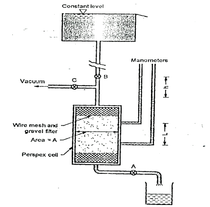
Fig.2.1: Constant head permeability test
K= =
=
Where q=v/t=discharge in m3/s
V=volume of water collected in m3 in time t sec
A=cross sectional area of specimen in m
h =level difference between the manometer tubes in m.
L =distance between manometer points in m
Key Takeaways:
Constant head method is based on measuring the volume of water flowing through a soil sample of known cross sectional area A and length L in time t under a constant head h of water.
2.5.2 Falling Head Method as per IS 2720:
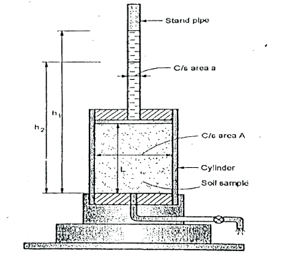
Fig.2.2: Falling head permeability test
K = 
Where, a =area of c/s of stand pipe.
A =area of soil sample.
L = length of soil specimen
and h1, h2=heights of water measured in the stand pipe at time t1 and t2
If t2-t1 then
K = 2.3
Key Takeaways:
This test is used to determine the permeability of fine-grained soils with very low permeability. Due to low permeability, the collected water will evaporate and will lead to wrong results in constant head test. Hence, this: test is used.
2.6.1 Pumping in test as per IS5529 Part-1:
- Pumping-in-test is more economic than pumping out test.
- It gives more reliable values than pumping-out-test.
- It gives the value of 'K' of strata very close to the hole but pumping-out-test gives the value of K for large area surrounded by the hole.
Generally, there are the types of pumping-in-test
Types of pumping-in-tests:
a. Single packer test
b. Double packer test
1. Open-end test:
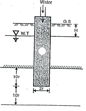
Fig.2.3: Open end test (constant discharge)
K =
Where, K = coefficient of permeability
H = difference of level between the inlet of casing and water table
q = discharge
r= inner radius of pipe casing


2. Packer test:
(a)Single-packer tests
(b) Double-packer tests.
(a)Single-packer tests:
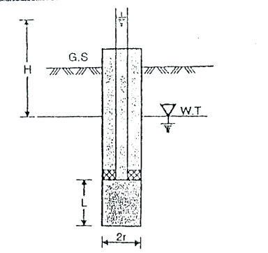
Fig.2.4: Single packer test (hole tested below W.T)
K=
if 10r > L >r, then
K =
Where, K =coefficient of permeability
H = difference of water level at the entrance and the ground water table for the hole tested below W.T i.e., water table
r = inner radius of hole
 =are hyperbolic sine
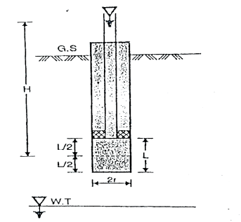
Fig.2.5: Single packer test (hole tested above W.T)

(b)Double-packer-test:
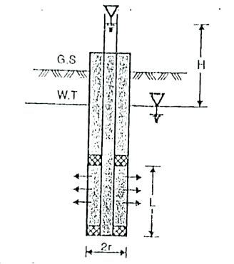
Fig.2.6: Double packer test (test section below W.T)
K=
Or if 10r > L > r, then
K=
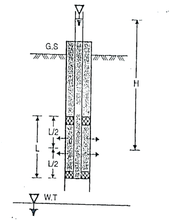
Fig.2.7: Double Packer test (test section above W.T)
Key Takeaways:
Types of pumping-in-tests are as follows:
1.Open-end test
2. Packer tests: Single packer test, Double packer test
2.6.2 Pumping out test as per IS5529 Part1:
Unconfined aquifer
Confined aquifer
(a) To find coefficient of permeability 'K' by using equations for unconfined aquifer:
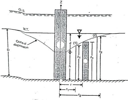
Fig.2.8:’K’ unconfined aquifer
Dupult's Assumptions:
Derivation of 'K' can be obtained by following Dupuit's assumptions.
i = 
8. Consider a flow through a cylindrical surface having height 'h' and at a radius distance 'r' from the centre of well.
q= KiA
K =coefficient of permeability
i = hydraulic gradient= dz/dr
A = total cross-sectional area of soil = 2 rz
rz
q=K )
) (2
(2
 =
= zdz
zdz
Integrating the above expression (2.9.1) for observation well I and 2, we get
 =
=
 k =
k = 
R = 3000d √K
Where, R = radius of influence in m
K = coefficient of permeability 'm'/sec.
d=drawdown in 'm'
R = { )(
)( )1/2}1/2
Where, t= time required to establish steady conditions
n = porosity
K =
Where, rw= radius of test well
R= radius of influence
D =depth of aquifer measured below the water table
h =depth of water in the well
Equation (iii) gives an approximate value of 'K' i.e., coefficient of permeability because the following reasons:
(b)To find 'K' by using equation for confined aquifer
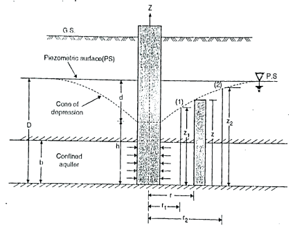
Fig.2.9:’K’ by confined aquifer
Let q discharge through cylindrical surface at a radial distance 'r' from the centre and z= height.
q=KiA ...by Darcy's law
q=K ( )(2
)(2 …...∴i=dz/dr and A=2
 rb
rb
 =
= (dz)
(dz)
Integrating the above equation, we get
∴K= 
Key Takeaways:
In this test, the water is pumped out from the wells which is especially drilled for this purpose. This test is generally used in practice so as to measure the coefficient of permeability of soil for large engineering projects.
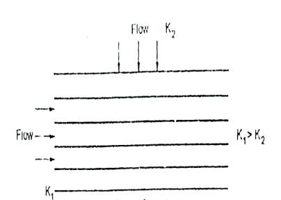
Fig.2.10: horizontal strata
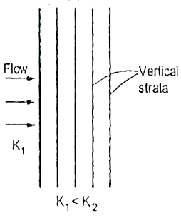
Fig.2. 11: Vertical strata
(1) Average permeability parallel to the bedding planes
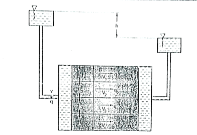
Fig.2.12: Flow parallel to bedding plane
q=q1, q2…. qn
Kx = 
(2) Average permeability perpendicular to the bedding planes
h=h1+h2+...hn
but h1=iL1 h2=iL2
h=iL1+iL2+iL3+…
Now, if KZ=average permeability perpendicular to the bedding plane.
We get,
Kz=
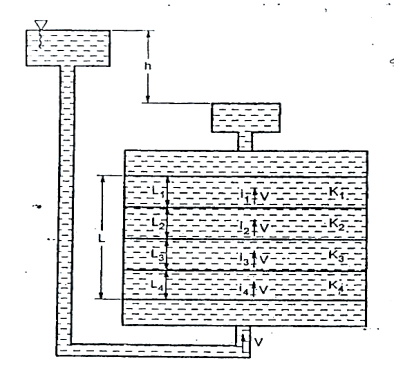
Fig.2.13: Flow perpendicular to bedding plane
Key Takeaways:
Stratified soils are those, which are formed by lager upon lager of carth or dust deposited upon one another. If the flow is parallel to the lagers or stratification, the permeability is maximum while the flow is perpendicular direction to the stratification occurs with minimum permeability.
It is given by,
Ps=h
Ps =  ×L
×L
Where, h=Hydraulic head,
Z= Length over which the head (h) is lost,
i = Hydraulic gradient,
 =Unit weight of water
Seepage force (F) is given by,
Fs= Ps. A= i.Z. A
A
Where A= Total cross-sectional area of the soil mass
 =Unit weight of water
The seepage pressure always acts in the direction of the flow.
The effective pressure (P) in the soil mass is given by
Pe=Z ± iz
± iz
For upward flow,
Pe=Z - iz
- iz
In upward direction, the effective pressure is decreased hence-ve sign.
For downward flow,
Pe=Z +iz
+iz
In downward direction, the effective pressure is increased hence +ve sign.
Key Takeaways:
The pressure exerted by water on the soil through which it percolates is known as seepage pressure.
i= ic =
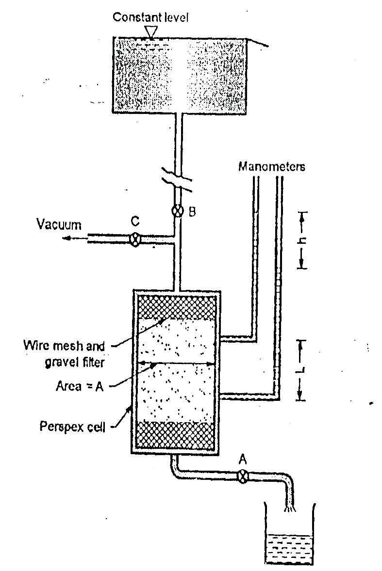
Fig.2.14: Quick Sand Condition
Key Takeaways:
When the seepage pressure becomes exactly equal to the submerged weight of the soil, through which the flow is taking place, the effective pressure becomes zero. In this case, the soil with less cohesion loses all its shear strength and soil particles move up in the direction of flow. This lifting of soil particles is known as quick sand condition.


 (
( )+
)+ (
( )=
)= (
( +
+
From which +
+ =0
=0
According to assumption 1.
While computing these quantities with the help of theoretical analysis following assumptions are made.
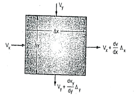
Fig.2.15: Two-dimensional flow
The quantity of water flowing into any element of volume is equal to the quantity which the quantity of water entering the element is equal to the quantity of water leveling it.
 (
( )+
)+ (
( )=
)= (
( +
+
From which +
+ =0 …... (1)
According to assumption 1,
Vx= Kx. ix =Kx
Vy= Ky. iy =Ky
Where, h =Hydraulic head under which water flows.
Kx and Ky= Coefficients of permeability in x and y direction.
Substituting these in Equation (i)
 +
+ =0
=0
We get,
 +
+ =0
=0
For an isotropic soil, Kx=Ky=K(say)
∴ +
+ =0
=0
Substituting  Kh =Velocity potential in Equation, we get
 +
+ =0
=0
This is the Laplace equation of flow in two dimensions.
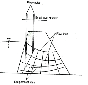
Fig.2.16: Flow lines and equipotential line
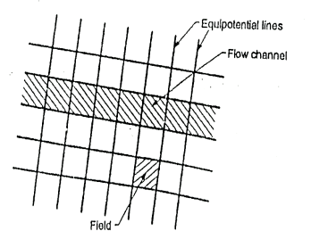
Fig.2.17: Flow net
Key Takeaways:
The grid, mesh or net formed by the intersection of equipotential lines and flow lines is called flow-net.
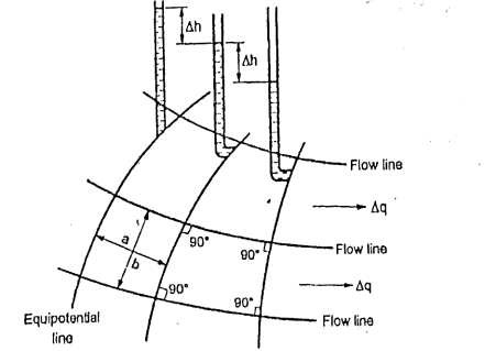
Fig.2.18: Part of flow net illustrating characteristics
Procedural steps:
F1f1, Emerging at right angles at UB running round the sheet pile and meeting TV at right angles.
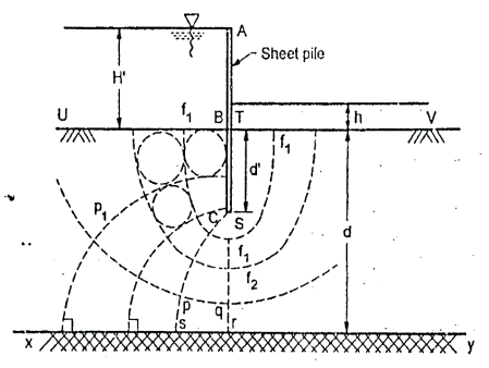
Fig.2.19: Flow net for sheet pile
Key Takeaways:
ABC is a sheet pile driven in pervious layer of depth d, the depth of embedment BC being d’. UB and TV are potential boundaries with known heads. BCST and xy are flow line boundaries because these are impervious surface across which water cannot pass. Flow lines will emerge at right angles from UB and end at right angles at TV. Because of symmetry flow not will symmetrical, about vertical axis.
Steps:
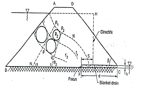
Fig.2.20: Flow net for earthen dam
References: