Back to Study material
GE

Unit - 4

Shear Strength of Soil


  • Shear force is the force applied along or parallel to a surface or cross-section, instead of being applied perpendicular to the cross-section.
  • Shear stress is this force divided by the area on which it acts. And the capacity to withstand the maximum shear stress without occurrence of failure is the shear strength of the material.
  • Failure of soil rarely occurs due to tension, as, if the soil is pulled from both directions, particles will separate and it will immediately collapse. So that tensile load can hardly be applied to soil.
  • Due to compression, the particles become more and more closely packed, so that density of soil and hence strength increase and thus, compression failure of soil is also rare.
  • That leaves us with shear failure, which is the most common mode of failure for any soil. Hence in foundation design, in earth road design, in carth dams, in retaining structures, in open canal design, in design of spillway apron shear strength of soil is important.
  • Key Takeaways:

    It is the force applied along or parallel to a surface or cross-section, instead of being applied perpendicular to the cross-section. Shear stress is this force divided by the area on which it acts. And the capacity to withstand the maximum shear stress without occurrence of failure is the shear strength of the material.


  • In most of the problems in soil mechanics such as those concerning the foundations of structures, earthwork engineering etc., the soil mass has to withstand shearing stresses, which are unlike in nature than the compressive stresses.
  • Shearing stresses tend to displace part of the soil mass relative to rest of the soil mass, Shear strength of a soil is the capacity of the soil to resist shearing stress.
  • It can be defined as the maximum value of shear stress that can be mobilized within a soil mass. If this value is equalled by the shear stress on any plane or surface at a point, failure will occur in the soil because of movement of a portion of the soil mass along that plane or surface.
  • The soil is then said to have failed in shear.
  • The shear strength depends upon:
  • Type of soil
  • Cohesion
  • Compaction.
  • Water content
  • Internal friction
  • Key Takeaways:

    Shear strength can be defined as the maximum value of shear stress that can be mobilized within a soil mass. If this value is equalled by the shear stress on any plane or surface at a point, failure will occur in the soil because of movement of a portion of the soil mass along that plane or surface.


  • Through a point in a loaded soil mass, soil mass is subjected to 3-D stress system or three-dimensional stress system and there are innumerable planes pass and stress components on each plane. These stress components depend upon the direction of the plane.
  • Even though the soil mass is subjected to 3-D stress system, the stresses in the third direction are not considered and to solve the many problems in soil engineering, the two-dimensional stress system (2-D stress system) is considered.
  • There are three typical planes mutually perpendicular to each other at every point in a stressed body.
  • Principal planes:

  • When three planes at every point in a stressed body subjected to normal stress and no shear stress acts, then threes planes are called as principal planes.
  • There are three principal planes as,

  • Major principal plane
  • An intermediate principal planes
  • Minor principal plane third
  • It can be noted that the third principal plane which is intermediate between major and minor principal plane is not relevant. Hence only major principal and minor principal plane are considered
  • Principal stresses:

  • There are two principal stresses like major and minor principal stresses are to be considered and third principal stress in the third direction is not much relevance.
  • Major principal stress (
    1): The normal stress without shear stress acting on the major principal plane is called as major principal stress (
    ).
  • Minor principal stress (
    ): the normal stress without shear stress acting on the minor principal plane is called as minor principal stress (
    .
  • The intermediate principal stress (
    ) is not much relevant, hence not considered in the many problems in geotechnical engineering, only major principal stress (
    ) and minor principal stress (
    ) are important.
  • Following equation shows the equation of circle,
  • +2   =2                         

    Where, = Normal stress

    = Shear stress

     1= Major principal stress

    = Minor principal stress

    The co-ordinates of centre of circle are =0 and

    = and its radius is

    Mohr's circle stress:
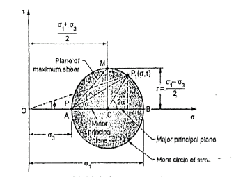
  • The circle on which the co-ordinates of points showing the normal and shearing stresses on inclined planes at a given point is termed as mohr circle of stress.
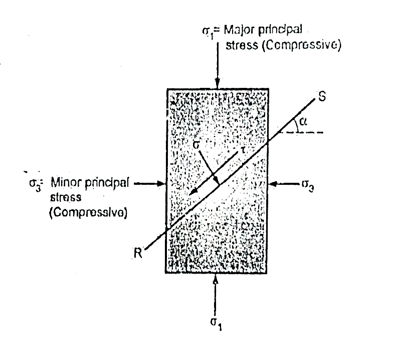
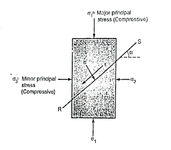
  • Fig. shows a cylindrical specimen of soil subjected to normal stresses a, and o, where a major principal stress and d, minor principal stress.
  • H:\unit4\IMG_20210519_201801.jpg

    Fig.4.1: Soil Specimen

  • By taking as radius as
    and centre at C at a distance of
    on the abscissa from origin 'O’. In Mohr circle of stress for soil specimen can be drawn as shown in Fig.
  • H:\unit4\IMG_20210519_201826.jpg

    Fig.4.2: Mohr’s stress circle for cylindrical specimen

  • From the pole P a line PP1 is drawn parallel to the plane RS as shown in Fig. The co-ordinates of the point P, gives the stress and 
    i.e., P, (
    ,
    ) fm the stress circle, <P1 CB=2
  • In Fig. the major principal plane is horizontal and therefore pre P is located by drawing a horizontal line through "B" and OB presents the major principal stress. The circle draws inserts at A and hence OA repents minor principal stress. Point B shows the major principal s
    ,
    ), whereas point A shows the minor principal trees
    ,
    )
  • Key Takeaways:

    The circle on which the co-ordinates of points showing the normal and shearing stresses on inclined planes at a given point is termed as mohr circle of stress.


  • Mainly shear failure in soil occurs by slippage of particle due to shear stress.
  • Shear stress at failure normally depend upon normal stresses on the potential failure plane.
  • According to Mohr soil failure is a function of normal stress applied on the soil.
  • i.e., f=f ()

    f = shear stress

    = normal stress

  • The shear stress at failure is called as shear strength.
  • Equation (i) becomes,

    f =s= f ()

    S =shear strength.

  • A curve as shown is obtained when normal and shear stress corresponding to failure are plotted are called as strength envelope.
  • Fig.4.3: Mohr’s Theory

    Columb later modified Mohrs equations and gave the following equation.

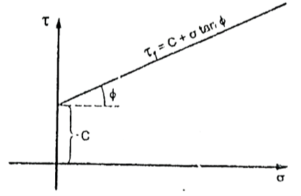
    S=c+

    Thus, Mohr envelope is replaced by straight Line
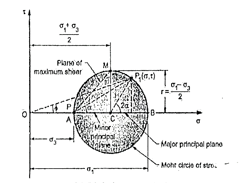
    Fig.4.4: Mohr’s coulomb envelope

    We can say that c is intercept on c axis and is angle made by envelope with axis. The component 'c' of shear strength is called as cohesion which is independent of normal stress which hold soil particle together and d-represent angle of internal friction. Failure occurs when Mohr circle touches failure envelope or one can say at a maximum obliquin (Bmax) in which resultant touches Mohr circle and when and c gives a critical combination failure occurs.

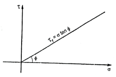
    Incase where c=0 the graph starts from origin and equation becomes.

    S=

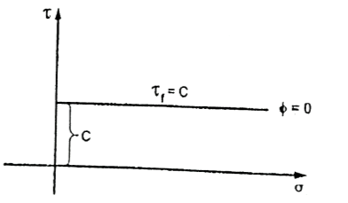
    In case where =0 i.e., friction less or fully cohesive soil the line will be horizontal. Later it will be found that c and depends upon number of factors like water content drainage conditions and lesting condition. Thus, terzaghi shows that the effective stress controls the shear strength and hence the equation gets modified

    :. s = c’+tan

    c' =Effective cohesion intercept

    Effective angle of shearing resistance

    = Effective stress

    This above equation is called as Mohr Coulomb equation for shear strength of soil.
    H:\unit4\IMG_20210519_201930.jpg

    Fig.4.5: Soil with internal friction and cohesion
    H:\unit4\IMG_20210519_201946.jpg

    Fig.4.6: Cohesionless soil

    H:\unit4\IMG_20210519_202007.jpg

    Fig.4.7: Frictionless soil

    Key Takeaways:

    Mainly shear failure in soil occurs by slippage of particle due to shear stress. Shear stress at failure normally depend upon normal stresses on the potential failure plane.


  • The principle of effective stress can be stated as
  • a)     Effective stress governs volume changes in soils.

    b)    Effective stress ( l) Total stress ()-pore pressure(uw)

    c)     Effective stress controls shearing strength of soils.

  • Many properties like volume change, permeability, shearing strength, compressibility etc depends upon the effective stresses.
  • The voids can totally be filled with water or partly with water and air. Shear stresses are to be carried only be the skeleton of solid particles. But in general, the total normal stress on any planes are the sum of two components.
  • :. Total stress = component of stress carried by solid particles + pressure in the fluid in the void space.


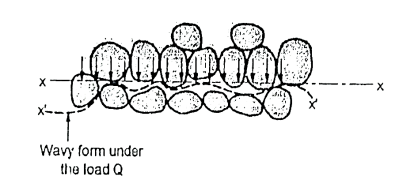
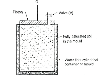
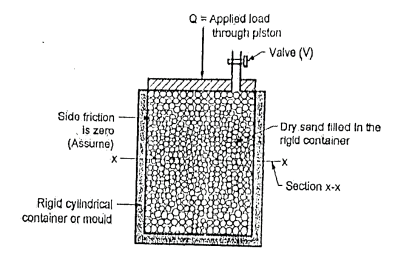
  • Consider a rigid cylindrical mould or container as shown in Fig. 4.7.1(a). The dry sand is filled in this rigid cylindrical mould. It is assumed that there is no side friction in the cylindrical container or mould.
  • Surface of the soil is subjected to load Q through a piston and this load is transferred to the dry soil grains filled in the container through their poin s of contact. The average stress at any section x-x can be determined as follows
  • av =

    Where, av =Average stress; A= sectional area of the cylinder

    Any plane like x-x do not pass through all the points of contact, but many of the grains are cut by the plane x-x and the actual points of contacts seems like a wavy form.

    The average stress which is responsible for the deformation of the soil mass is called as effective stress or intergranular stress see Fig. for better understanding. Note that o, o is the effective stress.
  • In another experiment, cylindrical mould is filled with the fully saturated soil and cylindrical mould is entirely made water tight. If the same load (Q) is placed on the piston, the load will not be transmitted to the soil grains but in case of Fig. the same load was transmitted to the soil grains (dry).
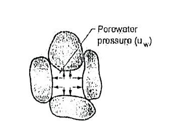
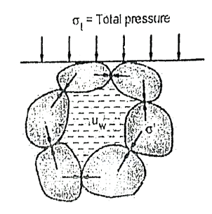
  • Pore Pressure: The pressure which is developed in the water due to external load transmitted to the water in the pore by assuming water to be incompressible is called as pore pressure or neutral stress (uw) which is shown in Fig.
  • H:\unit4\IMG_20210519_202024.jpg

    Fig.4.8: Specimen

    H:\unit4\IMG_20210519_202048.jpg

    Fig.4.9: Intergranular pressure

    H:\unit4\IMG_20210519_202107.jpg

    Fig.4.10: Pore water pressure

    H:\unit4\IMG_20210519_202130.jpg

    Fig.4.11: The effective stress principle
    H:\unit4\IMG_20210519_202158.jpg

    Fig.4.12: The effective stress principle

    uw = neutral stress=Q/A

    where, Q=load applied by piston

    A=sectional area of the cylinder

    Uw =pore pressure or neutral stress

  • In Fig., as soon as valve V is opened, there will be immediately, expulsion of water through the hole and this flow continues for some time and then stops. Note that expulsion of water from the pores decreases the pore water pressure, but increases the intergranular pressure. Hence at any stage; the total pressure split up between water and the points of contact of grains which make a new equation as follows:
  • Total pressure () = + uw

    Where, =Intergranular pressure

    Uw =pore water pressure or neutral stress.

    For no expulsion of water, uw = 0,

    Hence total pressure ()= Intergranular pressure ()

    Fig.shows the concept of total pressure, integranular pressure and pore water pressure.

  • =
    is called as effective stress equation where
    =effective stress,
    t=total pressure and uw= porewater pressure.
  • Key Takeaways:

    The pressure which is developed in the water due to external load transmitted to the water in the pore by assuming water to be incompressible is called as pore pressure or neutral stress.
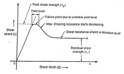

  • Let us consider an element of soil subjected to a varying shear stress under a constant normal stress.
  • Fig. shows the stress-strain curve for peak and residual shear strength. For low value of shear stress, soil is in clastic limit with a linear shear strain. When shear stress increases, then at a particular stress level, plastic shear start. The point at which plastic shear starts to develop is termed as 'yield".
  • When shearing resistance of soil increases with the plastic shear strain, then stage so developed for soil material is termed as strain harden.
  • Increase of shear resistance can only be caused by strain hardening.
  • H:\unit4\IMG_20210519_202219.jpg

    Fig.4.13: Peak and Residual shear strength

    Peak Shear Strength:

  • Resistance to a particulars maximum shear stress caused only by strain hardening is termed as peak shear strength or only shear strength of the soil.
  • The maximum shearing resistance decreases after yield point in some soils. Hence when the maximum shearing resistance decreases after the yield level, then soil is said to be strain softening.
  • Yield level is considered as unstable level and at the maximum peak strength, the soil is said to fail.
  • Residual Shear Strength:

  • When the shearing resistance comes at a constant level after a continued large strain then corresponding shear resistance at a constant level is termed residual shear strength.
  • Key Takeaways:

    Resistance to a particulars maximum shear stress caused only by strain hardening is termed as peak shear strength or only shear strength of the soil. When the shearing resistance comes at a constant level after a continued large strain then corresponding shear resistance at a constant level is termed residual shear strength.


    Cohesionless Soil

    Cohesive soil

    1.Gradation

    1.Plastic index

    2.Shape of particle

    2.Clay content

    3.Pressure

    3.Drainage condition

    4.Denseness

    4.Pressure

    5.Moisture


    For Cohesionless soil:

  • Gradation: Exhibit greater strength incase of well graded sand.
  • Shape: Max. angular and sharp edge particle more will be the strength
  • Pressure: With increase in confining pressure shear strength increases.
  • Denseness: More is denseness more is shear strength
  • Moisture: IFS and is saturated apparent cohesion is destroyed.
  • For Cohesive Soil:

  • Plasticity index: Value of decreases with increase in plasticity index
  • Clay content: As clay content increases angle of shearing resistance decreases.
  • Drainage condition: Less strength if drainage is not proper
  • Pressure: Shear strength of clay increases with increase in confining strength

  • Stress-Strain Behaviour of Sands:

  • The stress-strain behaviour of saturated sand specimen can be well studied by performing drained tests in direct shear tests or triaxial tests.
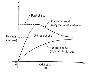
  • Two specimens of saturated sand are taken and one specimen is kept at a very high initial void ratio i.e., loose sand and other is kept at a very low initial void ratio i.e., dense sand. These two specimens can be used in consolidated drained (CD) tests. The test gives the results in the form of deviator stress and axial strain.
  • Fig.shows the graph of deviator stress against axial strain taken from the test results.
  • H:\unit4\IMG_20210519_202243.jpg

    Fig.4.14: Typical stress-strain behavior of sands from CD test

    In both the specimen, the cell pressure is kept constant and axial stress is increased the sample specimen fails in shear.

  • The stress-strain curve for the dense sand shows a definite peak or ultimate point of stress relatively low strain.
  • In Fig, when strain goes on increasing, the peak stress decreases and then stress becomes more or less constant. For further continuation of shearing of soil, the stage of deviator stress is termed as ultimate stress.
  • For shearing of loose sand, the stress increases with strain more gradually as compared to the dense sand and maximum deviator stress comes very close to ultimate stress value of dense sand.
  • The peak stress is used to define the shear strength. In case of loose sands, the maximum riress or stress value at an arbitrarily selected value of strain is used to define the shear strength.
  • Stress-Strain Behaviour of Clays:

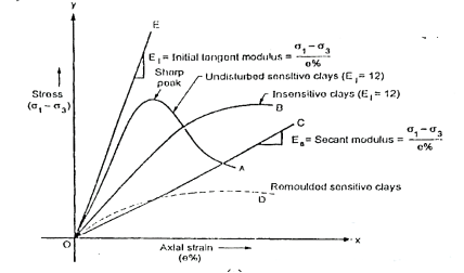
  • Fig. shows typical stress-strain behaviour of clays obtained from unconsolidated undrained conditions test (UU tests). Curve 'A' shows a sharp peak for uadisturbed clays of high sensitivity at a low strain.
  • H:\unit4\IMG_20210519_202306.jpg

    Fig.4.15: Typical stress-strain behavior of clays from UU test
     

    H:\unit4\IMG_20210519_202328.jpg

    Fig4.16: Brittle and plastic failure resp.
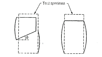
  • The sample specimen shears very clearly along a well-defined shear plane as shown in Fig. This shear failure is termed as brittle failure.
  • Curve 'D' shows plastic failure for remoulded sensitive clays i.e., soft clays due to continuous yield at a more or less constant stress resulting in the bulging effect on the cross-sectional area of specimen as shown in Fig.
  • In Fig., the curve 'B' shows an increase of stress with strain upto a certain stage and then there is slightly stress drop.
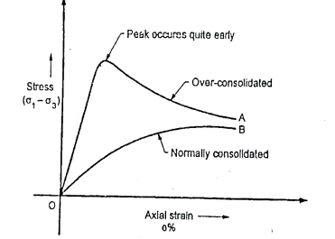
  • Fig. shows a typical stress-strain curves for normally consolidated and overconsoildated clay obtained from consolidated drained (CD) test.
  • H:\unit4\IMG_20210519_202351.jpg

    Fig.4.17: Stress-strain behavior of clay obtained from CD test


  • In Fig., the curve 'A' shows a greater strength for overconsolidated clays than normally consolidated clays as shown by curve B. In curve A, peak occurs quite early and the stress falls off as the strain increases which is a phenomenon called as work-softening or strain softening.
  • Key Takeaways:

    The stress-strain behaviour of saturated sand specimen can be well studied by performing drained tests in direct shear tests or triaxial tests.


    4.10.1 Direct Shear test:

  • This is the oldest shear test method in use and still most common because of its simplicity. It is also known as shear box test.
  • The soil specimen is confined in a metal box that is split horizontally.
  • If the specimen is fully or partially saturated, perforated metal plates and porous stones are placed above and below the specimen for drainage.
  • If the specimen is dry, solid metal plates are used.
  • A pressure pad is placed on top and the entire box is placed in a trolley.
  • The upper half of the box is fixed to a support through a proving ring and the lower half of the box is pushed at a constant rate of strain. A vertical load is applied on the pressure pad. At time of failure, shear stress is measured by the proving ring.
  • Then the test is repeated for another sample of the same soil, for a different vertical load on the pressure pad.
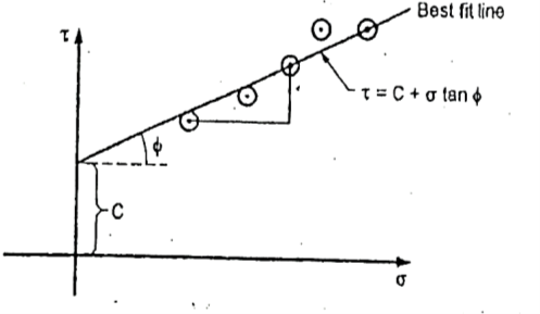
  • 4-5 repeatitions are made for 4-5 different normal loads. By dividing normal load and corresponding shear load at failure by the internal horizontal area of the shear box, the normal and shear stress values can be obtained.
  • These values are plotted and a best fit straight line through these points gives the strength envelope. From this C and
    can be determined.
  • The arrangement is shown in Fig.
  • H:\unit4\IMG_20210519_202409.jpg

    Fig.4.18: Test arrangement


    H:\unit4\IMG_20210519_202426.jpg

    Fig.4.19: Graph of direct shear test

  • Thus, the direct shear test is the most commonly used test as it has following advantages.
  • Advantages and Disadvantages of Direct Shear Test: 

    Advantages:

  • Test is simple and fast.
  • Drainage is quick due to less thickness of sample.
  • CD and CU tests takes relatively small period, because of quick drainage and rapid dissipation of pore water pressure.
  • Test is ideally suited for drained tests on cohesionless soils.
  • The direct shear test apparatus is relatively cheap.
  • Disadvantages:

  • Failure of soil specimen is always along a horizontal plane, which may not be very realistic.
  • If any large soil particles or stones etc. are present at failure plane, it will give wrong results.
  • Actual field condition is not simulated in the set up.
  • Measurement of pore pressure is not possible.
  • Key Takeaways:

    This is the oldest shear test method in use and still most common because of its simplicity. It is also known as shear box test.

    4.10.2 Triaxial Compression test:

  • A Casagrande invented the triaxial compression test so as to remove the disadvantages of the direct shear test. The triaxial compression test is most efficient and versatile of all the shearing testing methods of any type of soil. In this method, drainage condition can be controlled. Pore water pressure can be measured accurately and also volume changes can be measured with the help of triaxial test.
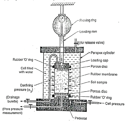
  • Fig.shows the triaxial cell in which the soil sample is subjected to confining pressure (
    ) by applying pressure to water in the cell. Note that there is no rotation of the principal stresses during the test and the failure plane is not forced. The soil sample can fail on any weak plane or can simply bulge. In short, the soil sample may subject to brittle failure or plastic failure.
  • H:\unit4\IMG_20210519_202446.jpg

    Fig.4.20: Triaxial cell

  • The triaxial test is carried out on a cylindrical sample er specimen of soil which is being taken securely in the rubber membrane. Cylindrical specimen of soil having a length to diameter ratio as 2. The usual sizes of specimen of soil are 76 x 38 mm or 100 x 50 mm.
  • The traixal test apparatus consists of the following components:
  • loading frame
  • proving ring
  • pressure apparatus
  • loading arm
  • porous disc
  • triaxial cell
  • pressure chambers
  • sample trimmer
  • rubber 'O' ring
  • air release value
  • Triaxial cell is a perspex cylinder which is attached to the base with rubber seals so as to make the cell water tight. The pressure cylinder controls the constant pressure in the triaxial cell. Sometime a separate compressor is used to apply fluid pressure in the cell. There is a separate pore pressure measg equipment which measure the pore pressure developed in the soil specimen during test. Cylindrical soil specimen is enclosed in a rubber membrane.
  • A stainless-steel piston running through the centre of the top from which the vertical compressive load (deviator stress) can be applied on the soil specimen under test.
  • Porous discs are placed on the top and bottom of the soil specimen and rubber membrane is sealed by rubber 'O' ring depending upon the drainage conditions of the test.
  • Test procedure:

    Following are the various points which explains the test procedure.

  • The cylindrical specimen is kept on a saturated porous disc resting on the pedestal of the triaxial cell.
  • The cylindrical specimen is enclosed by a rubber membrane and sealed at the top and bottom by rubber 'O' ring. The rubber membrane prevents the penetration of water into the soil specimen.
  • The triaxial cell is filled with water at the required pressure through cell pressure unit. This water pressure is subjected to the soil specimen to all-around. This water pressure is called as cell pressure or the confining pressure (
    )). Cell pressure acts radially on the vertical surface of the specimen and axially at the top and bottom.
  • By keeping constant cell pressure, additional axial stress is applied through the ram gradually until the soil specimen fails. This t additional axial stress is also called as deviator stress produces shear stresses within the soil sample on all planes except the horizontal and vertical planes.
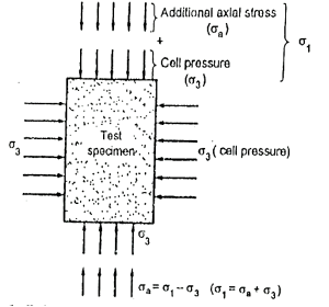
  • Fig. shows the principal stresses on the triaxial specimen
    H:\unit4\IMG_20210519_202510.jpg

    Fig.4.21: Principal stress on the triaxial specimen

    In the first stage, cell pressure ()) is applied on the test specimen and in the second stage, deviator stress (ie. additional axial stress, ) is applied on the sample until the failure of the soil specimen.

    =deviator stress ()+cell pressure ()

    =-

    5.     During triaxial loading, outlet valve of drainage burette is kept open so as to have the result for drained loading. This outlet valve is kept closed for an undrained loading.

    6.     The drainage burette or drainage outlet is connected to the pore pressure apparatus by which pore pressure can be measured.

    7.     The drainage burette is also connected to the volume measuring apparatus so as to measure change in volume for drained loading.

    Advantages of Triaxial Test:

    Following is the various advantage of triaxial test

  • A Casagrade developed the triaxial test in his research and removed the disadvantages of direct shear test.
  • There is a complete control during conducting the shear test under all the three drainage conditions.
  • Porewater pressure and volume change are precisely measured during the test.
  • There is uniform stress distribution on the failure plane.
  • State of stress within the soil sample during any stage of the test and at the failure of soil sample is completely determinate.
  • Disadvantages of Triaxial Test:

  • The apparatus in triaxial test is bulky, costly and elaborate.
  • Triaxial test takes longer period in case of drained test as compared with that in a direct shear test.
  • Key Takeaways:

    The triaxial compression test is most efficient and versatile of all the shearing testing methods of any type of soil

    4.10.3 Unconfined Compression test:

  • This test is especially useful for homogenous cohesive clayey soils. It cannot be used for dry.
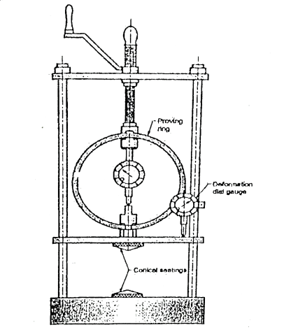
  • In this test, a cylindrical soil specimen is fitted between two plates, with slight conical projections for firm grip on the specimen, and a compressive axial stress is applied on it till it fails.
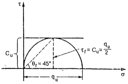
  • Since the test is quick, water is not allowed to drain out from the specimen, hence it is an undrained test. If qu, is the stress at failure, then the shear strength is given as,
  • f=Cu=qu/2

  • The arrangement is shown in Fig. The Mohr's circle in this case is drawn and the various parameters are shown.
  • Internal friction is assumed to be zero as this test can be used only for purely cohesive soils.
  • H:\unit4\IMG_20210519_202535.jpg

    Fig.4.22: Test arrangement

    H:\unit4\IMG_20210519_202557.jpg

    Fig.4.23: Mohr’s circle

    Advantages of Unconfined Compression Test:

  • It is quick and convenient for meaning shear strength.
  • It is useful for homogeneous cohesive clayey soil.
  • It is suitable for measuring unconsolidated, undrained shear strength of saturated class
  • It is used to measure insitu strength and very useful for field test.
  • Disadvantages of Unconfined Compression Test:

  • This test cannot be carried out on coarse grained soils like sands and gravels and also not carried out on fissured clays.
  • The test result may be misleading for the soils for which
    0.
  • Key Takeaways:

    This test is especially useful for homogenous cohesive clayey soils. It cannot be used for dry.

    4.10.4 Vane shear test, their suitability for different types of soil and advantages & disadvantages:
  • This is a test preferred when shear strength of soil in the undisturbed state is required.
  • For some soils, it is very difficult to get undisturbed sample. In that case, the field vane shear test is very useful.
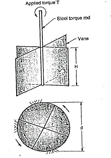
  • In this test, a shaft to which 4 vanes are welded is slowly penetrated in the ground (in an undisturbed large sample brought to the laboratory) and by turning the shaft slowly, the torque required for failure of soil is measured.
  • At the time of failure, a cylindrical portion of soil is sheared off from rest of the soil mass.
  • H:\unit4\IMG_20210519_202715.jpg

    Fig.4.24: Vane shear test


  • By using following formula, shear strength Tf can be found out.
  • =

  • When the vanes penetrate well below the top surface of the soil, or,
  • =

  • When the vanes are flush with the top surface of soil.
  • Where,= shear strength,

    T = torque applied,

    H =height of vanes,

    d =diameter of circle formed on rotating vanes.

    The arrangement is shown in Fig.

    Plotting Strength Envelope:

  • In all the thear tests, plotting of strength envelopes is done with the help of Mohr's circle. Two or more samples must be tested for drawing the strength envelope.
  • Only in unconfined test, only one Mohr's circle is drawn and a horizontal tangent to it gives strength envelope.
  • In case of other tests, two or more Mohr's circles corresponding to the results are drawn and a best-fit common tangent to these circles, gives the strength envelope.
  • Determining Shear Strength Parameters of Soil:

  • The cohesion 'C' measured in N/mm² and the angle o are called the parameters of the shear strength Tf measured in N/mm². As shown in Fig.after plotting any test results, the shear strength parameters C and
    can be directly measured from the graph.
  • In case of direct and triaxial tests (triaxial test is not in the syllabus), C and
    can be determined without plotting the values simply by solving simultaneous equations generated by putting different values of
    and
    in the equation
    =c+
  • Key Takeaways:

    This is a test preferred when shear strength of soil in the undisturbed state is required.


    There are three types of drainage conditions for shear tests as explained follows:

    1. Consolidated-undrained conditions (CU condition)

  • Before shear, the specimen or soil sample is allowed to consolidate and the drainage is allowed until the consolidation is completed in first stage.
  • During shear, no drainage is allowed or drainage is stopped in second stage this test is also termed as CU test or 'R' test.
  • 2. Consolidated drained conditions (CD condition)

  • Before shear, the specimen is allowed to consolidate during drainage conditions in first stage.
  • During shear; drainage is allowed in second stage. Note that rate of shearing is kept very low to ensure that a fully drained condition exists such that excess pore water is zero.
  • This test is also termed as CD test.
  • 3. Unconsolidated-undrained condition (UU condition)

  • Before and after shear, no drainage and consolidation are allowed; that means before application of axial stress or shear in first stage, drainage and consolidation is not allowed and after shear or application of axial stress, no drainage and consolidation of soil sample is permitted in second stage of test.
  • Due to unconsolidated and undrained condition, the test can be carried out quickly in a less time and therefore this test is also called as 'quick test' or 'UU test.
  • Key Takeaways:

  • Consolidated-undrained conditions (CU condition)
  • Consolidated drained conditions (CD condition)
  • Unconsolidated-undrained condition (UU condition)

  • Definition: The ratio of unconfined compressive strength of an undisturbed sample of soil to the unconfined compressive strength of the remoulded sample of same soil at the same water content as in undisturbed soil is called as sensitivity (St).
  • St =

  • Where, qu= unconfined compressive strength of an undisturbed sample of soil or clay
  • qu’=unconfined compressive strength of remoulded sample of soil or clay at the same water content as in the undisturbed soil
  • Sensitivity is a measure of the loss in strength of soils and remoulding on the consistency of a cohesive soil.
  • Following table shows natural clay deposits classified into four different categories based on the value of sensitivity:
  • Sr.no.

    Sensitivity

    Classification

    1

    1-14

    Normal

    2

    4-8

    Sensitive

    3

    8-16

    Very sensitive

    4

    16-32

    Slightly quick

    5

    32-64

    Medium quick

    6

    Greater than 64

    Quick

    7

    Less than 1

    Stiff clay


    Key Takeaways:

    The ratio of unconfined compressive strength of an undisturbed sample of soil to the unconfined compressive strength of the remoulded sample of same soil at the same water content as in undisturbed soil is called as sensitivity.


  • Thixotropy is a Greek word in which thix means touch and tropo means change, overall meaning of thixtropy is any change which occurs by touch.
  • Thixotropy is the property of certain clays or soil by virtue of it gradually regains its lost strength with time if remoulded clay is allowed to rest without change in water content.
  • In short, if a remoulded soil sample having the sensitivity more than one is allowed to stand without change in water content and disturbance, then it may regain some parts of its original strength and stiffness. This increase in strength of soil sample is termed as thixotropy.
  • Thixotropy has more practical importance in geotechnical engineering. In pile-driving operations, thixotropy plays important role. For example. There is a strength loss of soil, when a pile is driven into the ground. In such case, one can easily know regaining of shear strength after the pile has been driven and left in place for some time with the help of thixotropy.
  • Key Takeaways:

    It is the property of certain clays or soil by virtue of it gradually regains its lost strength with time if remoulded clay is allowed to rest without change in water content.

    References:

  • Soil Mechanics and Foundation Engineering by Dr.B.C. Punmia, Laxmi Publication
  • Geotechnical Engineering by T.N. Ranamurthy & T G Sitharam, S Chand Publications.
  • Principles of Geotechnical Engineering by Braj M. Das, Cengage Learning.
  • Geotechnical Engineering by P. Purushothma Raj, Tata Mc Grawhill.
  •  


    Index
    Notes
    Highlighted
    Underlined
    :
    Browse by Topics
    :
    Notes
    Highlighted
    Underlined