Unit - 1
Fundamental of Structure and Analysis of Redundant beam
- Basics:
- Structural Analysis:
It means envelop Axial Force, shear force, Bending& Torsion moment at various cross-se of Structural member. It also aims finding deformations.
2. Object of Analysis:
Structural design required for safety and serviceability. Safety depends on stresses due to structural actions and serviceability de on deformation.
3. Structural actions:
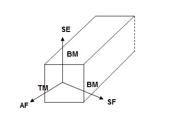
4. Axial force (AF):
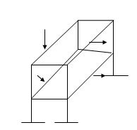
Force acting normal to cross-section and passing through CG.
5. Shear force (SF):
Force acting parallel to cross-section.
6. Bending moment (BM):
Moment vector parallel the cross-section
7. Torsion Moment (TM):
Moment Vector normal to the cross-section
- Sign Conventions:
- Static Calculations
∑Fx = 0, ∑Fy = 0 & ∑M = 0
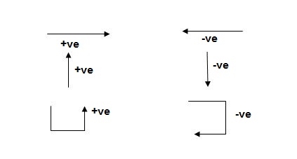
2. For Structural Actions
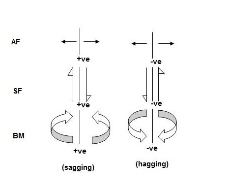
- Types of Structures
- Skeletal structure: Assembly of line member Beams, Frames, Truss, etc.
- Surface structures: Ex – Plater, Shells, Dome
- Volume structures: Dams, Retaining walls etc.
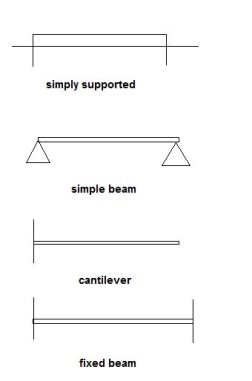
- Types of Skeletal structures:
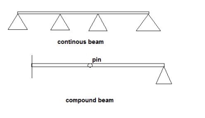
- Beams
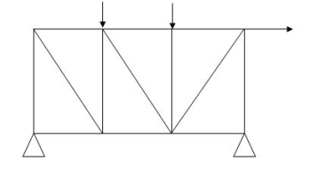
2. Pin connected plane trusses
2D Structure
All pin Joints
Only joint loads
Only Axial forces
3. Pin connected space trusses
- 3D structure
- All pin joints
- Only joint loads
- Only Axial forces
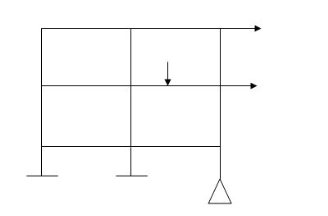
4. Rigid jointed plane Frames
1. 2D structure
2. Rigid joints
3. Joint & member loads
4. Member have AF, SF, BM
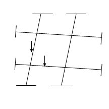
5. Grids
1. 2D structure
2. Rigid joints
3. Joint & member loads normal to the plane of structure.
4. Shear force, bending moment, Torsional.
6. Rigid jointed space frames
- 3D structure
- Rigid joints
- Joint & member loads
- AF, SF, BM, TM
6. Rigid joint
1. All members meeting at rigid joint will rotate by some amount
2. Algebraic sum of member end moment = 0
7. Pin joint:
1. Members can rotate independently
2. Each member end moment =0
- Classification of Structure:
- Based on structural geometry
a) Skeleton or one-dimensional structure
b) Surface or two-dimensional structure
c) Solid or three-dimensional structure
2. Based on structural action
3. Based on structural system
- Based on structural geometry
(a) Skeleton or one-dimensional structure:
These are the structures which can be idealized to a series of straight or curved lines i.e., Beams, Frames etc.
(b) Surface or two-dimensional structures
These are the structures which can be idealized to a plane or curved surfaces e.g., slab and shells etc.
(c) Solid or three-dimensional structures:
These are structures which neither be idealized to a skeleton nor to a plane or curved surface e.g., massive foundation etc.
2. Based on Structural Actions
Structural element subjected to axial forces i.e., may be tensile or compressive or both
Structural element subjected to moments i.e., may be bending moment or twisting moment or both.
Structural element subjected to (i) and (ii) (i.e., axial forces as well as moments) for example,
Beams carry their loads by developing bending moments and shear forces.
Columns carry their loads by developing axial forces and/or moments to any one and/or both axial directions.
Plane trusses carry their loads by developing axial forces.
Plane frames carry their loads by developing axial forces, bending moments and shear forces.
Key takeaways:
- Skeletal structure: Assembly of line member Beams, Frames, Truss, etc.
- Surface structures: Ex – Plater, Shells, Dome
- Volume structures: Dams, Retaining walls etc.
- These are the structures which can be idealized to a series of straight or curved lines i.e., Beams, Frames etc.
1. Concept of Indeterminacy:
There are two type of indeterminacy that we can classify based on reaction support condition and its displacement
- Static indeterminacy
- Kinematic indeterminacy
2. Static Indeterminacy:
The Static Indeterminacy (SI) for beams and frames is described as,
SI = nu — ne
Where,
Nu = Number of unknown assist reactions
Ne = Number of equations of equilibrium
In fashionable for a -dimensional shape, there are 3 equations of equilibrium (ne = 3) and for a 3-dimensional shape there are six (ne = 6).
For a truss, static indeterminacy entails each outside and inner indeterminacy due to the inner individuals in a truss.
Static indeterminacy (SI) within side the case of a truss is described as,
SI = b + r — 2j
Where,
b = Number of individuals within side the truss
r = Number of reactions on the supports
j = Number of joints within side the truss
Sign Conventions
1). Static Calculations
∑F x = 0, ∑F y = 0 & ∑M = 0
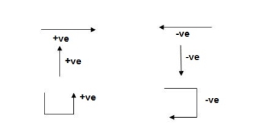
For Structural Actions
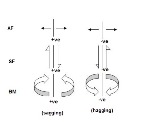
Degree of static indeterminacy (Dsi)
Dsi = No of Unknown Actions –No of Eqn,
Dsi = R – E
External Indeterminacy
When we can't discover assist reactions the use of legal guidelines at statics, its miles referred to as externally indeterminate structure.
Internal Indeterminacy
When we can't discover inner member movements the use of legal guidelines of statics, its miles referred to as internally indeterminate structure.
Boundary condition
Displacement Re stained Displacement allow
Δx, Δy, ϴz Nil
Δy, ϴz, Δx
Δx, Δyϴz
Dsi for beams = R – E
Where,
R = No of assist reactions
E = No of Equilibrium equations
Note: For one inner pin, no of extra equations of equilibrium are = m – 1
m = no of individuals linked via way of means of pin.
Sr. No Structure R E Dsi
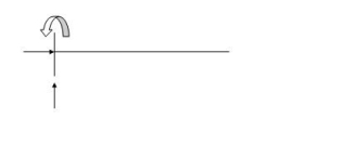 3 3 0
3 3 0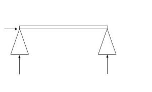 3 3 0
3 3 0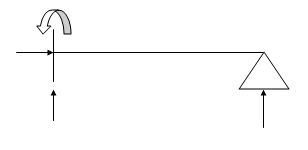 4 3 1
4 3 1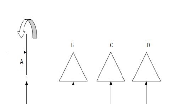 6 3 3
6 3 3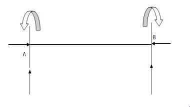 6 3 3
6 3 3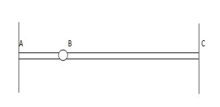 6 4 2
6 4 2
7. 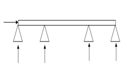 5 4 1
5 4 1
8. 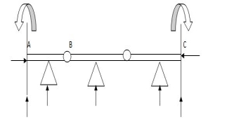 9 5 4
9 5 4
Dsi for Trusses:
(Dsi)Total = (m + R) – (2J)
Where,
M = No of members
R = No of support reactions
J = No of Joints
(Dsi) external = R – 3
(Dsi) internal = (Dsi) total – (Dsi)ext
Dsi = (M + R) – 2j
Sr. No Truss m R J (Dsi)Total
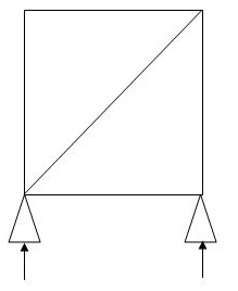 5 3 4 0
 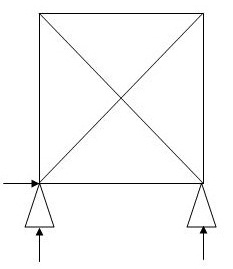 6 3 4 1
(Dsi)int.=0
(Dsi)ext= 1
3. 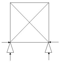 5 4 4 1
(Dsi)int.=1
(Dsi)ext= 0
4. 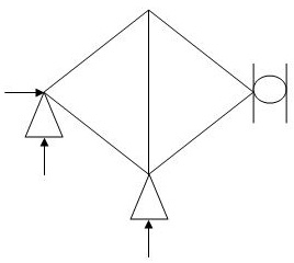 5 4 4 1
(Dsi)int.= 1
(Dsi)ext= 0
5. 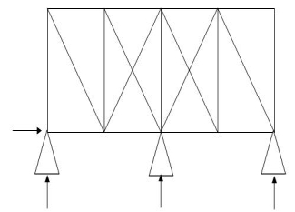 19 4 10 3
(Dsi)int.= 1
(Dsi)ext= 2
6. 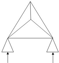 6 4 4 2
(Dsi)int. = 1
(Dsi)ext = 1
7. 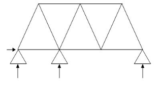 11 4 7 1
(Dsi)int. = 1
(Dsi)ext = 0
8. 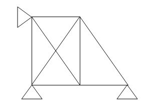 8 4 5 2
(Dsi)int.= 1
(Dsi)ext = 1
9. 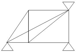 8 5 5 3
(Dsi)int. = 2
(Dsi)ext = 1
10. 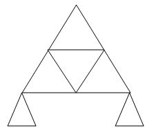 9 3 6 0
Dsi for Frames:
(Dsi)Total = 3m + R – 3J
(Dsi) external = R – 3
(Dsi) Internal = (Dsi) Total – (Dsi)ext
Sr. No Structure m R J (Dsi)Total
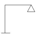 2 5 3 2
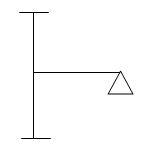 3 8 4 5-2 =3
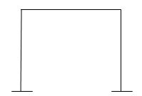 6 6 6 6
 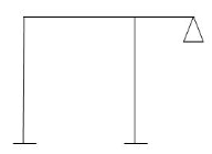 4 8 5 5
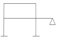 13 8 11 14-4 = 10
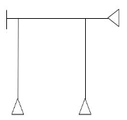 5 9 6 6
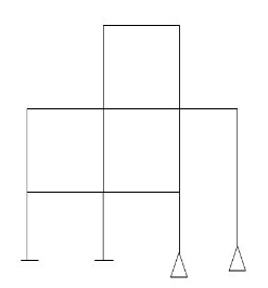 15 10 13 16
Note:
For Frames:
(Dsi)ext = R – 3
(Dsi)int = 3{No of closed loops}
(Dsi)total = (Dsi)ext + (Dsi)int
& for Int. Pin Reduced (Dsi)Total by (m-1)
- Arches
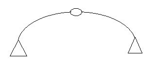 Dsi = 0
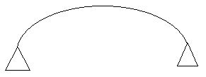 Dsi = 1
Examples:
1)

R – E = 9-4 = 5
Dsi = 5
2)
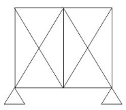
R – E = 5-3
(Dsi)ext = 2
(Dsi)int = 2
(Dsi)Total – (Dsi)ext = (Dsi)Int
Dsi = m + R – 2j
= 11 + 5 – 2(6)
= 4
3)
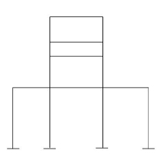
(Dsi)ext = 9
(Dsi)int. = 9
R = 12
m = 16
j = 16
(Dsi)T = (3m + R) – 3j - 18
(Dsi)T = (Dsi) + (R - 3)ext
= 18 – 9
= 92>. Axial deformation of members is neglected.
Dki for beams:
 1)
1) ΔXB, ΔYB, ϴB = 2
2)  ϴB = 1
 3)
3)  ΔXB&ϴB = 1
4)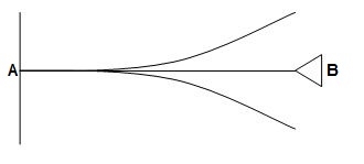 ΔYB&ϴB = 2
5) ϴB, ϴC, ϴD = 3
6)  ϴB, ϴC, ϴDΔYD = 4
7)  = 0
= 0
8)  ϴBA, ϴBC, ΔBy = 3
9)  ϴB, ΔBy = 2
10) ϴDE, ϴDC, ΔDy = 6
ϴC, ϴBΔBy
11)  ϴA, ϴB,
ϴD, ϴCB, ϴCD = 10
ΔYC, ϴE
ΔYE, ΔYF1, ϴE
3. Degree of Kinematic Indeterminacy (Dki):
It is defined as no of unknown joint displacement in the structure.
Note:
- Joint means point of support, free end of member and point of intersection of members.
- Axial deformation of members is neglected.
Dki for beams:
 1>.
1>. ΔXB, ΔYB, ϴB = 2
2>.  ϴB = 1
 3>.
3>.  ΔXB&ϴB = 1
4>. 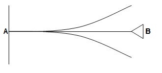 ΔYB&ϴB = 2
5>.  ϴB, ϴC, ϴD = 3
6>.  ϴB, ϴC, ϴDΔYD = 4
7>.  = 0
= 0
8>.  ϴBA, ϴBC, ΔBy = 3
9>.  ϴB, ΔBy = 2
10>.  ϴDE, ϴDC, ΔDy = 6
ϴC, ϴBΔBy
11>.  ϴA, ϴB,
ϴD, ϴCB, ϴCD = 10
ΔYC, ϴE
ΔYE, ΔYF1, ϴE
Dki for frames:
Frames are of two types
i). Non-sway frames
Ii). Sway Frames
Sway – Horizontal translation of beam in a frame is called as sway.
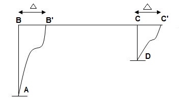
Sway = Δ
Identification of non-sway frame:
Frame having any one end of beam hinged or fixed is non-sway frame.
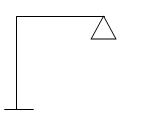
Ii). If end of the beam is not hinged or fixed, check symmetry of frame about vertical axis.
If frame is symmetric, it is non-sway Frame. Symmetry shall be checked with respect to
a). Geometry b). EI c). Loading d). Support
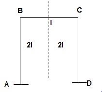
Sr No Dki
1). ϴB, ϴC = 2 at (Rigid joint = 1 rotation)
2). ϴC, ϴB, ΔBy = 3
3). ϴB, ϴC, ϴD, ϴF = 4
4). ϴE, ϴC, ϴBC, ϴBA = 4
5). ϴB, ϴC, ϴD, Δsway = 4
6). ϴB, ϴCB, ϴCD, Δsway = 4
7). ϴB, ϴC, ϴD, ΔCy, Δsway = 5
8). ϴB, ϴC, ϴD, ϴE, ϴF, Δsway1, Δsway2 = 7
9). ϴB, ϴC, ϴD, ϴE, ϴG, ΔEy, ΔswayDG = 7
Dki for Trusses:
1). In case of trusses at pin joint count two translations (Δx, Δy)
2). At roller support count one translation
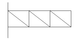
3). For hinged support count zero translation.
Procedure to analyze the beams:
Step 1) Identify the degree of redundancy of the beam
Step 2) Treat the number of reaction equal to degree to redundancy as redundant
Step 3) Find the bending moment at any section x due to imposed loads in terms of redundant and
Step 4) Find the unknown reaction using the theorem of least work

Step 5) Draw final FBD
Problems:
- Analyze the propped cantilever beam loaded as shown in fig. Assume EI constant
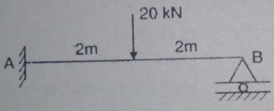
Solution:
- Degree if redundancy Dsi= 4-3=1
- Treat RB as redundant
- Find M and
 The values are tabulates as under
Segment | Origin | Limit | M |  |
BC | B | 0-2 | RB-X | X |
CA | C | 0-2 | RB(x+2)-20x | X+2 |
4. Find RB
Apply theorem of least work
According to theorem of least work
We have,


Find RA and MA


Draw BMD
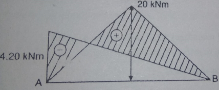
2. Find reaction at support for the propped cantilever loaded as shown in fig.
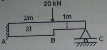
Solution:
- Degree of redundancy Dsi= r-3 = 4-3 =1
- Treat Rc as redundant
- Find M
- Find

Segment | Origin | Limit | EI | M |  |
CB | C | 0-1 | EI | Rc.x | x |
BA | B | 0-2 | 2EI | Rc. (x+1) _20x | X+1 |
5. Find reaction Rc:
Apply the theorem of least work


6. Find RA and MA


Key takeaway:
Steps:
- Identify the degree of redundancy of the beam
- Treat the number of reaction equal to degree to redundancy as redundant
- Find the bending moment at any section x due to imposed loads in terms of redundant and

- Find the unknown reaction using the theorem of least work

5. Draw final FBD
References:
1. Structural Analysis: Deodas Menon---Narosa Publishing House.
2. Structural Analysis: Thandavamoorthy---Oxford University Press.
3. Structural Analysis: A Matrix Approach by Pundit and Gupta, McGraw Hills.
4. Structural Analysis by Hibbler, Pearson Education.
5. Structural Analysis: M. M. Das, B. M. Das---PHI Learning Pvt Ltd. Delhi.
6. Fundamentals of Structural Analysis: 2nd ed---West---Wiley.
7. Theory of Structures: Vol. I & II by B. C. Punmia, Laxmi Publication.
8. Theory of Structures: Vol. I & II by Peru mull & Vaidyanathan, Laxmi Publication.
9. Fundamentals of Structural Analysis: K. M. Leet, Vang, Gilbert—McGraw Hills
10. Matrix Methods for structural engineering. By Gere, Weaver.
11. Introduction to the Finite element method, Dr. P.N. Godbole, New Age Publication, Delhi.
12. Finite element Analysis, S.S. Bhavikatti, New Age Publication, Delhi.
13. Basic Structural Analysis: Wilbur and Norris.