Unit - 3
Slope-Deflection Method
1. Slope Deflection Method
- Slope=

- Deflection=

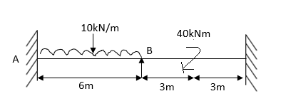
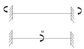
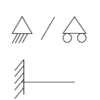
- Sign Convention


- Simply supported Beam

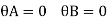
At support  form
form 
At the simply supported end
 is always zero.
 is always zero.
2. Cantilever beam

1.  =0 at the fixed end at force end

 At Fixed end
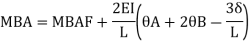
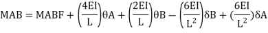
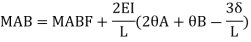
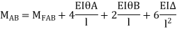
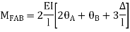
2. Slope deflection equation:
When a member of a structure is loaded, it deforms from its original position and internal forces are developed. The end moments can be expressed in terms of
(i) Fixed end moments (FEM) of the member due to transverse loading on the member
(ii) The slopes or rotations at the end
(iii) The end deflections or joint translations. These expressions are called as Slope-Deflection equations.
There are two slope deflection equations for each member.
These slope deflection equations are derived from superposition of the end moments caused by various actions and displacement.


Similarly
Where,
 = be the slope or rotation at joint A
 = be the slope or rotation at joint B.
 = be the end deflection or translation of joint A.
 = be the end deflection or translation of joint B.
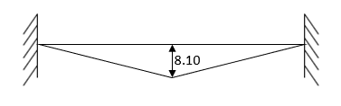
 B/A = Relative translation of joint B with respect to joint A
 AB Angle between the unreformed member and the line joining the deflected joints.
Here  >
>  Therefore
  B/A is positive
MAB = Moment at A of member AB
МВА = Moment at B of member BA
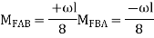
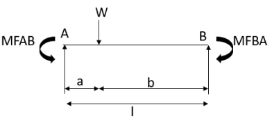
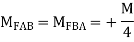
3. Fixed End Moments: Standard Cases Fixed End Moments
Standard Cases
1.
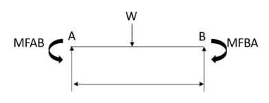

2.
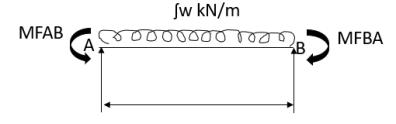
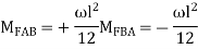
3.

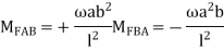
4.

5.


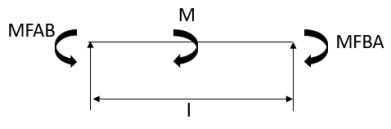
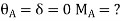
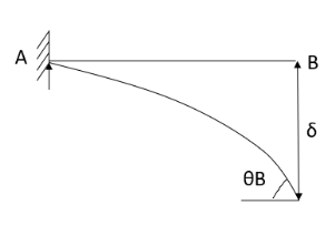
4. Derivation of slope Deflection Method
- In beam, a continuous beam ABCD, consider AB part and take fixed end moments and rotation at support as given below
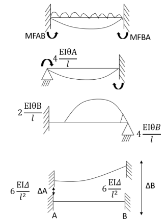
As per the diagram
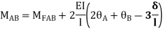
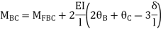
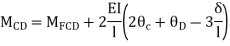
Slop deflection equations are


.
5. Types of numerical for slope deflection method
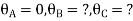
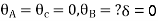
1. The beam is without sink (is zero.)
2. Beam with sink (is given)
3. Analyze of the frame without sink
4. Analyze the frame with the sink.
6. Steps for analysis of the slope deflection method
1. Find unknown slope .
.
2. Find fixed end moment
3. Apply the slope deflection equation.


4. Use the joint equilibrium equation at the joint.
5. Find final moments.
6. Find relation by equation &Draw SFI
7. Draw BMD


Problems:
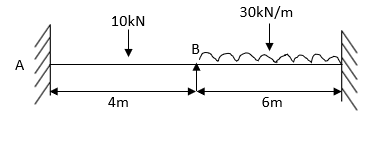
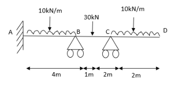
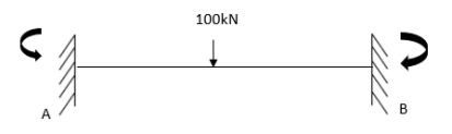
- Analyze the continuous beam shown in figure Draw also B.M. And S.F. Diagram
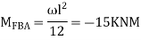
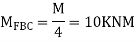
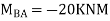
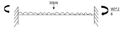
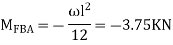
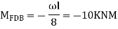
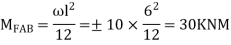
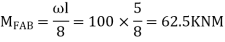
Step-1 Find fixed end moments


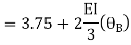
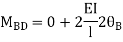
Step-II Slope deflection method


Step-III Apply equilibrium condition at joint


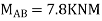
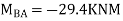
Step-IV Find final moments.


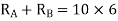
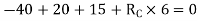
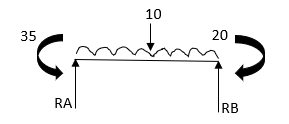
Step-V Find reaction
S.F. At A Take a moment at A is


SFD & BMD

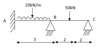
2. Determine support moments & draw BMD for the beam shown by using S.D.

Step-I) Find Dki
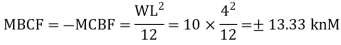
Step II) Find fixed end moments

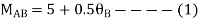
For BC Beam

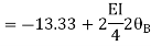
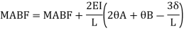
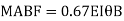
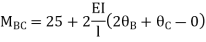
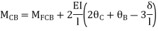
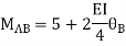
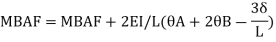
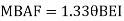
Step-III) Apply the SD equation
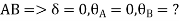
AB=>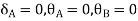


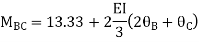
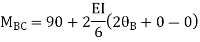
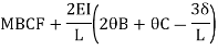
BC=>


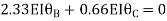
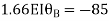
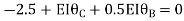
Step- IV) Apply equilibrium condition joint B


 ------- due to Hinge support


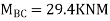
Put in equation (1) (2) (3) & (4)


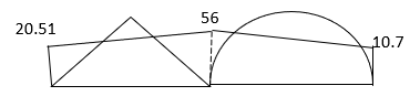
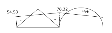
Draw BMD Diagram

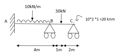
3. Analyze the continuous beam ABCD by S.D. Method draw BMD

Modify Diagram

Step- I) Fixed end moment

Apply S.D. Equation


Joint equilibrium equation
Joint at B


BMD and SFD

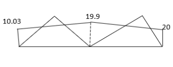
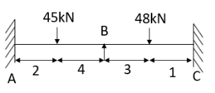
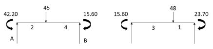
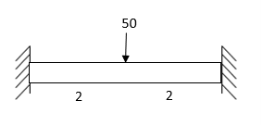
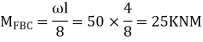
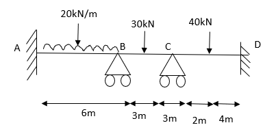
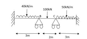
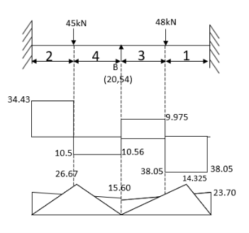
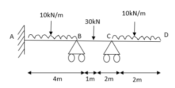
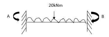
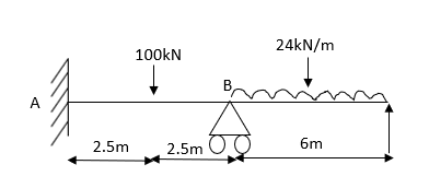
4. Analyze the continuous beam as shown in the figure by S.D. Method Draw BMD
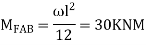
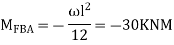
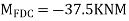
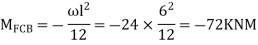
Step 1) Find fixed end moment


 KNM
KNM

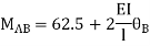
S.D. Equation
Span AB


Joint equilibrium equation
Joint B


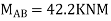
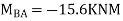
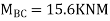
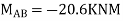
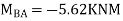
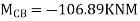
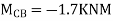
 KNM
KNM


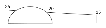
SFD

BMD

5. Analyze the continuous beam by S.D. Equation
Find fixed end moments:


Apply S.D. Equation
AB=>


 2)
2)
BC=>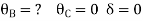


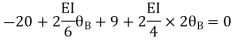
Joint equilibrium condition


BMD

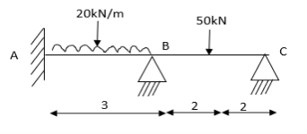
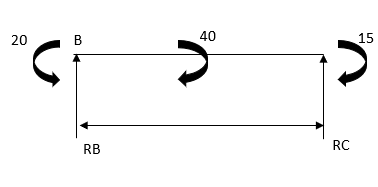
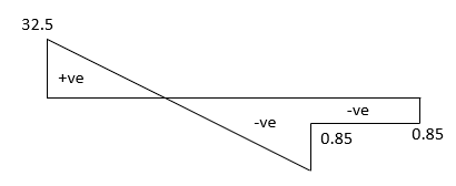
6. Analyze the beam by slope deflection method. Draw SFD and BMD
Solution:
Step 1) Dki = 2 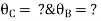
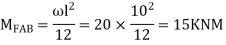
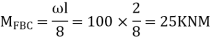
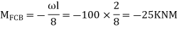
Step 2) Find Fixed End Moments
For AB


For BC


For CD


Apply S.D. Equation


Joint equilibrium condition


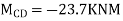
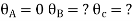
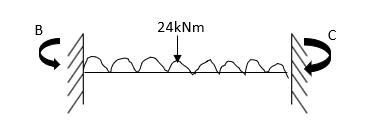
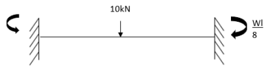
7. Determine the final moments by slope deflection method take EI is constant.

Step 1) Dki = 2
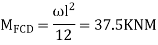
Step 2) Find fixed end moments


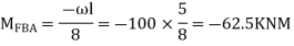
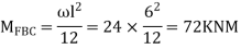

Step 3) Apply S.D. Equation


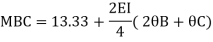
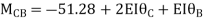
For beam BC

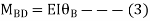
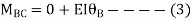
 --------(3)

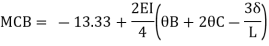
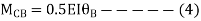
 -------(4)
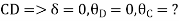
OR
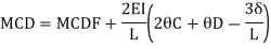
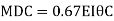
For member, BC apply modified equation
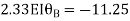
Step4) Joint equilibrium equation:


9.5 + 1.46 EI  + 0.33EI
 -------(A)

0 -------(B)
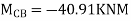
Equating equation, A & B get 
OR
Apply this condition to the modified equation


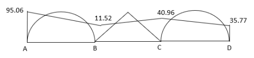
Step 5) BMD

Problems based on sink
Sink means deflection which occurs due to load which is acting on the beam
Note: always take EI in terms of KNM2
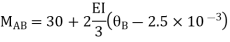
- Analyze continuous beam ABCD having
Point B is sunk by 2.5mm also draw BMD
Step 1) Dki = 2 


Step 2) Fixed end moments


STEP 3) Apply S.D. Equation
AB=>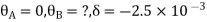 ,l = 3m


BC=>


Step 4) Apply equilibrium condition
Joint B


Joint C


 KNM
KNM
 KNM
KNM
 KNM
KNM

 KNM
KNM
 KNM
KNM
BMD

Key takeaway:
Steps:
1. Find unknown slope .
.
2. Find fixed end moment
3. Apply the slope deflection equation.

4. Use the joint equilibrium equation at the joint.
5. Find final moments.
6. Find relation by equation &Draw SFI
7. Draw BMD
Problems:
- Analyze the portal frame using slope deflection method.
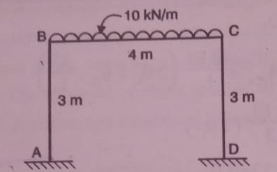
Solution:
It is symmetrical non-sway frame
Step 1) To find degree of kinematic indeterminacy
Dki= 2
Unknown displacement
Known displacement:
Step 2) To find fixed end moments


Step 3) To write slope deflection equation
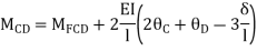
Member AB


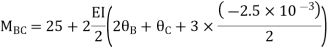
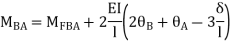
Member BC
Member CD


Step 4) To apply condition of equilibrium
At joint B
Adding equation 1and 2


Due to symmetry


Step 5) To find end moments at joint


Step 6) Draw BMD and SFD
SFD
BMD

Problems:
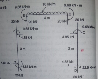
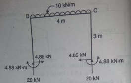
- Analyze the portal frame as shown by SD method draw BMD

1. Non-sway
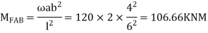
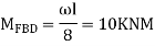
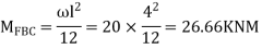
2. Find fixed end moments


AB =>


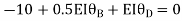
Joint equilibrium condition
Joint at B


2. Analyze the frame by SD method by BMD
Step 1) Find Dki

Step 2) Find fixed end moments

 ----due to no loading
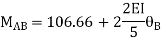
Step 3) S.D. Equation
AB =>


BD =>


Step 4) Equilibrium condition joint B


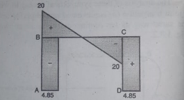
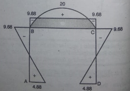
BMD

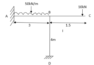
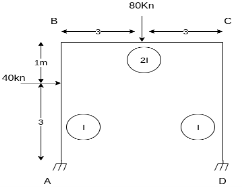
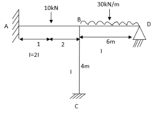
3. Analyze the frame shown in Figure support A is fixed B& C are winged. Draw BMD

Step 1) Non sway & Dki =
Step 2) Find a fixed end


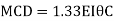
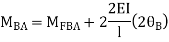
Step 3) S.D. Equation
For AB Span l =6m,  ,I =2I,


For BD Span l =4m,  , I =I,


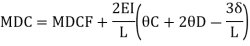
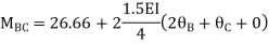
For BC Span l =4m,  ,I =1.5I,


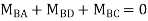
Step4) Equilibrium condition joint B


 +
+ +
+  =0
=0
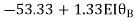
-16.67+3.83 +
+ +
+ ---------(A)
 ------(B)
 --------(C)
Equating Eq A, B & C you will get 


Final moment:


Problem on sway Frame
- Analyze the frame shown in fig slope deflection method
Step 1) Sway Frame: due to lateral loud frame in sway
Find Fixed Ends Moments:
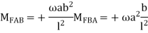
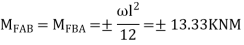
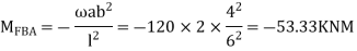
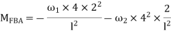
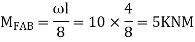
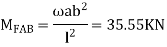
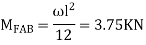
M FAB =  =
=  = 7.5KKNM
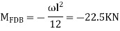
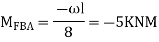
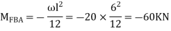
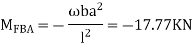
MFBA =  =
=  = -22.5KNM
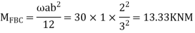
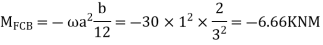
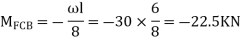
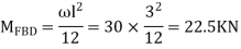
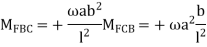
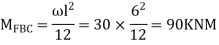
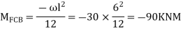
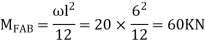
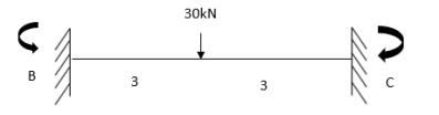
M FBC = M FCB = =
=  =
=  60 KNM.
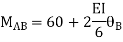
Apply Slope Deflection equations
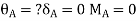
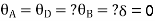
For AB: ƟA=0, ƟB =?
MAB = MFAB (2ƟA+ ƟB-
 )
)
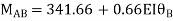
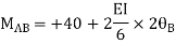
MAB = 7.5 +  ------------1)
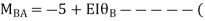
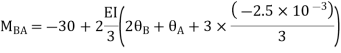
MBA = -22.5 +  ---------------2)
For BC:  =?
=?
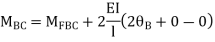
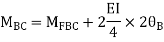
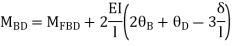
MBC = +60+ (
( ) -------3)
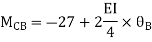
MCB = -60+ (ƟB
(ƟB ) -------------4)
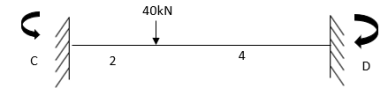
MDC = MFDC (2ƟD+ ƟC-
 )
)
MDC =  (ƟC-
(ƟC- ) ---------5)
MCD =  (2ƟC-
(2ƟC- ) --------6)
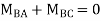
4) Apply joint equilibrium equation
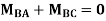
MBA+MBC = 0
-22.5 +  = 0 ---------------(A)
MCB+MCD = 0
-60+ (ƟB
(ƟB ) +
) + (2ƟC-
(2ƟC- )= 0 ------------(B)
Shear equation: HA +HD -40= 0 --------------7)
For AB Column
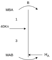
- HA 4 +MAB + MBA+ 40 *1=0
4HA = MAB + MBA+ 40 *1
Put Equation 1&2
4HA =7.5 +  -----(8)

This Fig
4HD = MDC+MCD
Put Equation 5 & 6
4HD =  (ƟC-
(ƟC- ) +
) + (2ƟC-
(2ƟC- ) ---------9)
Put equation 8 & 9 in Equation (7) Equation u will get equation (C)
Then Equating Equation (A, B, &C)
QB = -39.25/EI
QC = 19.25/EI
 = 110/EI
Final moments
MAB = 29.12 KNM
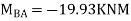
MBA = -20.5 KNM
MBC = 20.5 KNM
MCB = -60.51 KNM
MCD = 60.51KNM
MDC = +50.875 KNM
Key takeaways:
Steps:
- To find degree of kinematic indeterminacy
- To find fixed end moment
- To write slope deflection equation
- To find moments at end
- Draw BMD
References:
1. Structural Analysis: deodas Menon---Narosa Publishing House.
2. Structural Analysis: Thandavamoorthy---Oxford University Press.
3. Structural Analysis: A Matrix Approach by Pundit and Gupta, McGraw Hills.
4. Structural Analysis by Hibbler, Pearson Education.
5. Structural Analysis: M. M. Das, B. M. Das---PHI Learning Pvt Ltd. Delhi.
6. Fundamentals of Structural Analysis: 2nded---West---Wiley.
7. Theory of Structures: Vol. I & II by B. C. Punmia, Laxmi Publication.
8. Theory of Structures: Vol. I & II by Peru mull & Vaidyanathan, Laxmi Publication.
9. Fundamentals of Structural Analysis: K. M. Leet, Vang, Gilbert—McGraw Hills
10. Matrix Methods for structural engineering. By Gere, Weaver.
11. Introduction to the Finite element method, Dr. P.N. Godbole, New Age Publication, Delhi.
12. Finite element Analysis, S.S. Bhavikatti, New Age Publication, Delhi.
13. Basic Structural Analysis: Wilbur and Norris.
Unit - 3
Slope-Deflection Method
1. Slope Deflection Method
- Slope=

- Deflection=

- Sign Convention
- Simply supported Beam
At support  form
form 
At the simply supported end
 is always zero.
 is always zero.
2. Cantilever beam
1.  =0 at the fixed end at force end

 At Fixed end
2. Slope deflection equation:
When a member of a structure is loaded, it deforms from its original position and internal forces are developed. The end moments can be expressed in terms of
(i) Fixed end moments (FEM) of the member due to transverse loading on the member
(ii) The slopes or rotations at the end
(iii) The end deflections or joint translations. These expressions are called as Slope-Deflection equations.
There are two slope deflection equations for each member.
These slope deflection equations are derived from superposition of the end moments caused by various actions and displacement.
Similarly

Where,
 = be the slope or rotation at joint A
 = be the slope or rotation at joint B.
 = be the end deflection or translation of joint A.
 = be the end deflection or translation of joint B.
 B/A = Relative translation of joint B with respect to joint A
 AB Angle between the unreformed member and the line joining the deflected joints.
Here  >
>  Therefore
  B/A is positive
MAB = Moment at A of member AB
МВА = Moment at B of member BA
3. Fixed End Moments: Standard Cases Fixed End Moments
Standard Cases
1.

2.


3.

4.

5.
4. Derivation of slope Deflection Method
- In beam, a continuous beam ABCD, consider AB part and take fixed end moments and rotation at support as given below

As per the diagram
Slop deflection equations are
.
5. Types of numerical for slope deflection method
1. The beam is without sink (is zero.)
2. Beam with sink (is given)
3. Analyze of the frame without sink
4. Analyze the frame with the sink.
6. Steps for analysis of the slope deflection method
1. Find unknown slope .
.
2. Find fixed end moment
3. Apply the slope deflection equation.


4. Use the joint equilibrium equation at the joint.
5. Find final moments.
6. Find relation by equation &Draw SFI
7. Draw BMD

Problems:
- Analyze the continuous beam shown in figure Draw also B.M. And S.F. Diagram

Step-1 Find fixed end moments


Step-II Slope deflection method


Step-III Apply equilibrium condition at joint


Step-IV Find final moments.

Step-V Find reaction

S.F. At A Take a moment at A is


SFD & BMD
2. Determine support moments & draw BMD for the beam shown by using S.D.
Step-I) Find Dki

Step II) Find fixed end moments


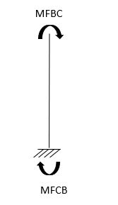
For BC Beam


Step-III) Apply the SD equation
AB=>


BC=>


Step- IV) Apply equilibrium condition joint B


 ------- due to Hinge support


Put in equation (1) (2) (3) & (4)


Draw BMD Diagram
3. Analyze the continuous beam ABCD by S.D. Method draw BMD

Modify Diagram
Step- I) Fixed end moment


Apply S.D. Equation


Joint equilibrium equation
Joint at B


BMD and SFD

4. Analyze the continuous beam as shown in the figure by S.D. Method Draw BMD

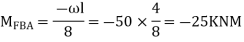
Step 1) Find fixed end moment

 KNM
KNM


S.D. Equation
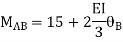
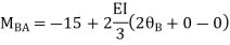
Span AB


Joint equilibrium equation
Joint B


 KNM
KNM


SFD
BMD
5. Analyze the continuous beam by S.D. Equation

Find fixed end moments:

Apply S.D. Equation
AB=>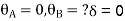


 2)
2)
BC=>


Joint equilibrium condition


BMD


6. Analyze the beam by slope deflection method. Draw SFD and BMD

Solution:
Step 1) Dki = 2 
Step 2) Find Fixed End Moments
For AB
For BC


For CD
Apply S.D. Equation


Joint equilibrium condition


7. Determine the final moments by slope deflection method take EI is constant.
Step 1) Dki = 2
Step 2) Find fixed end moments


Step 3) Apply S.D. Equation


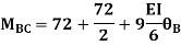
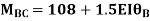
For beam BC

 --------(3)
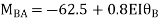

 -------(4)
OR
For member, BC apply modified equation


Step4) Joint equilibrium equation:


9.5 + 1.46 EI  + 0.33EI
 -------(A)

0 -------(B)
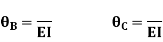
Equating equation, A & B get 

OR
Apply this condition to the modified equation


Step 5) BMD
Problems based on sink
Sink means deflection which occurs due to load which is acting on the beam
Note: always take EI in terms of KNM2


- Analyze continuous beam ABCD having

Point B is sunk by 2.5mm also draw BMD

Step 1) Dki = 2 


Step 2) Fixed end moments


STEP 3) Apply S.D. Equation
AB=> ,l = 3m


BC=>


Step 4) Apply equilibrium condition
Joint B


Joint C


 KNM
KNM
 KNM
KNM
 KNM
KNM
 KNM
KNM
 KNM
KNM
BMD
Key takeaway:
Steps:
1. Find unknown slope .
.
2. Find fixed end moment
3. Apply the slope deflection equation.


4. Use the joint equilibrium equation at the joint.
5. Find final moments.
6. Find relation by equation &Draw SFI
7. Draw BMD
Problems:
- Analyze the portal frame using slope deflection method.

Solution:
It is symmetrical non-sway frame
Step 1) To find degree of kinematic indeterminacy
Dki= 2
Unknown displacement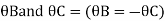
Known displacement:

Step 2) To find fixed end moments

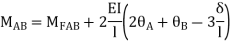
Step 3) To write slope deflection equation
Member AB


Member BC


Member CD


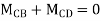
Step 4) To apply condition of equilibrium
At joint B
Adding equation 1and 2

Due to symmetry


Step 5) To find end moments at joint


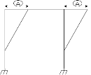
Step 6) Draw BMD and SFD


SFD

BMD
Problems:
- Analyze the portal frame as shown by SD method draw BMD
1. Non-sway
2. Find fixed end moments


AB =>


Joint equilibrium condition
Joint at B


2. Analyze the frame by SD method by BMD

Step 1) Find Dki
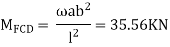
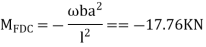
Step 2) Find fixed end moments

 ----due to no loading
Step 3) S.D. Equation
AB =>


BD =>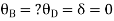


Step 4) Equilibrium condition joint B


BMD
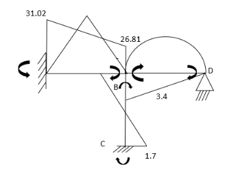
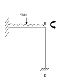
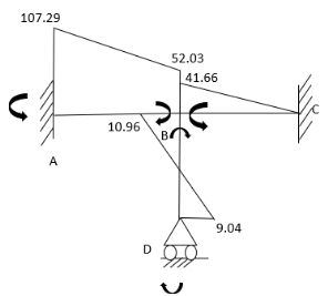
3. Analyze the frame shown in Figure support A is fixed B& C are winged. Draw BMD
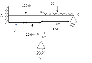
Step 1) Non sway & Dki =
Step 2) Find a fixed end


Step 3) S.D. Equation
For AB Span l =6m,  ,I =2I,


For BD Span l =4m,  , I =I,


For BC Span l =4m,  ,I =1.5I,


Step4) Equilibrium condition joint B


 +
+ +
+  =0
=0
-16.67+3.83 +
+ +
+ ---------(A)
 ------(B)
 --------(C)
Equating Eq A, B & C you will get 


Final moment:


Problem on sway Frame
- Analyze the frame shown in fig slope deflection method

Step 1) Sway Frame: due to lateral loud frame in sway

Find Fixed Ends Moments:
M FAB =  =
=  = 7.5KKNM
MFBA =  =
=  = -22.5KNM
M FBC = M FCB = =
=  =
=  60 KNM.
Apply Slope Deflection equations
For AB: ƟA=0, ƟB =?
MAB = MFAB (2ƟA+ ƟB-
 )
)
MAB = 7.5 +  ------------1)
MBA = -22.5 +  ---------------2)
For BC:  =?
=?
MBC = +60+ (
( ) -------3)
MCB = -60+ (ƟB
(ƟB ) -------------4)
MDC = MFDC (2ƟD+ ƟC-
 )
)
MDC =  (ƟC-
(ƟC- ) ---------5)
MCD =  (2ƟC-
(2ƟC- ) --------6)
4) Apply joint equilibrium equation
MBA+MBC = 0
-22.5 + 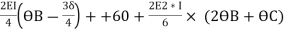 = 0 ---------------(A)
MCB+MCD = 0
-60+ (ƟB
(ƟB ) +
) + (2ƟC-
(2ƟC- )= 0 ------------(B)
Shear equation: HA +HD -40= 0 --------------7)
For AB Column

- HA 4 +MAB + MBA+ 40 *1=0
4HA = MAB + MBA+ 40 *1
Put Equation 1&2
4HA =7.5 +  -----(8)
This Fig
4HD = MDC+MCD
Put Equation 5 & 6
4HD =  (ƟC-
(ƟC- ) +
) + (2ƟC-
(2ƟC- ) ---------9)
Put equation 8 & 9 in Equation (7) Equation u will get equation (C)
Then Equating Equation (A, B, &C)
QB = -39.25/EI
QC = 19.25/EI
 = 110/EI
Final moments
MAB = 29.12 KNM
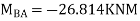
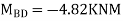
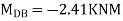
MBA = -20.5 KNM
MBC = 20.5 KNM
MCB = -60.51 KNM
MCD = 60.51KNM
MDC = +50.875 KNM
Key takeaways:
Steps:
- To find degree of kinematic indeterminacy
- To find fixed end moment
- To write slope deflection equation
- To find moments at end
- Draw BMD
References:
1. Structural Analysis: deodas Menon---Narosa Publishing House.
2. Structural Analysis: Thandavamoorthy---Oxford University Press.
3. Structural Analysis: A Matrix Approach by Pundit and Gupta, McGraw Hills.
4. Structural Analysis by Hibbler, Pearson Education.
5. Structural Analysis: M. M. Das, B. M. Das---PHI Learning Pvt Ltd. Delhi.
6. Fundamentals of Structural Analysis: 2nded---West---Wiley.
7. Theory of Structures: Vol. I & II by B. C. Punmia, Laxmi Publication.
8. Theory of Structures: Vol. I & II by Peru mull & Vaidyanathan, Laxmi Publication.
9. Fundamentals of Structural Analysis: K. M. Leet, Vang, Gilbert—McGraw Hills
10. Matrix Methods for structural engineering. By Gere, Weaver.
11. Introduction to the Finite element method, Dr. P.N. Godbole, New Age Publication, Delhi.
12. Finite element Analysis, S.S. Bhavikatti, New Age Publication, Delhi.
13. Basic Structural Analysis: Wilbur and Norris.


