Unit - 4
Moment Distribution Method
Moment Distribution Method (MDM) is an iteration procedure developed by Cross Hardy in 1930. Therefore, this method is sometimes called as the 'Cross Hardy Method'.
This method starts with the assumption that all points in an indeterminate structure are fixed temporarily against rotation and displacement.
The fixed end moment (FEM) induced by the loading on the spans are written down at each joint.
Then, the joint is released one at a time in succession. Because of the release of joints, unbalanced moments arise at the joints.
These unbalanced moments distributed at the joints in proportion to the stiffness of the members meeting at the joints.
Then these distributed moments are carried over to the far end of the members. Because of the carry-over moments at joints, again unbalanced moments are created which are further distributed and carried over.
In this manner the iteration is performed in successive cycles of operation till the value of joints becomes significant. At this stage, iteration is stopped and the moments at each joint is algebraically summed up.
The sum of the moments at the end of each span at a joint is the required final end moment.
MDM method is quite different than slope deflection method though it is a displacement or stiffness method. Without calculating values of displacement end moments are obtained by successive iteration.
2. Stiffness factor
It is ratio of moment of inertia to the length of the beam is called stiffness factor of beam.
Moment required to rotate an end by a unit angel when rotation is permitted at that end is called stiffness of the beam
Stiffness of the beam AB=
Types of far end support | K |
| I/L |
2. If far end is simply supported Roller support, Internal hinged and overhang | 3I/4L |
3. Carry over factor:
It is defined as the ratio of moment developed at far or adjacent end of the moment applied at the near end.
The ratio of carryover moment to applied moment is called carry-over factor.
Carryover factor=
Types of toes and support
| ½ |
2. Intermediate support | ½ |
3. Rigid joint | ½ |
4. Roller hinged, internal | 0 |
5. Overhanging | 0 |
6. If for the end is fixed | 1/l |
7. If for the end is simply roller internal hinged, I overhung | 3I/4L |
4. Distribution factor
It is ratio of the stiffness of member to the total stiffness of the joint where all the members are meeting.
A moment which tends to rotate without translation a joint to which several members are connected will be divided amongst connected member in proportion to their stiffness.
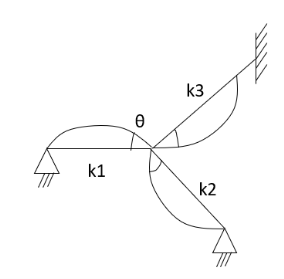
Distribution factor (DF) 
Thus, distribution factor is the ratio of the stiffness of member to the total stiffness of the joint where all members are meet.
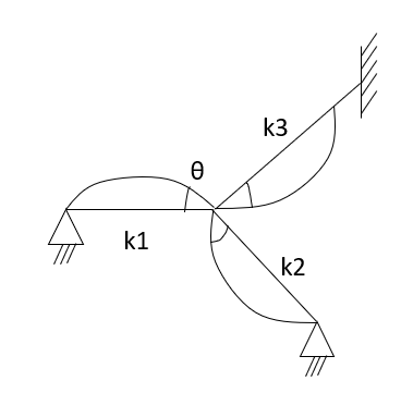

5. Application of MD method to continuous beam with fixed ends: -
Examples: To find stiffness
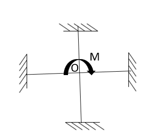


Then consider at the B end
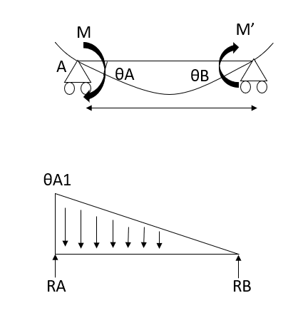


Carryover factor = 


Put 


Distribution factor =>
Key takeaway:
Steps for analysis of moment distribution method
Distribution factor is=
K=stiffness -it depends on the support condition.
1. Far end fixed &intermediate support =
2. The far end simply supports = 
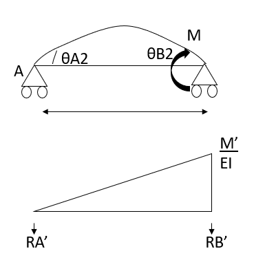
COF - support
O - Simply support
½ - fixed
½ - intermediate
Problems:
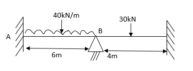
AB=> 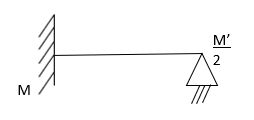
Step 1) Fixed end moment


Step 2) Distribution factor
Draw distribution table
Joint | Member | K |
|
|
B | BA
BC |
|
| 0.4
0.6 |
Step 3) Moment Distribution
1) Moment distribution Table
0.4 | 0.6 | |||
Member | AB BA | BC CD | ||
Fixed end
Balancing | 120 - 120
42 | 15 -15
63 | ||
COF
Balancing | 210 0 | 31.5 | ||
Final moments
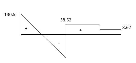
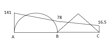
| 141 -78 | 78 16.5 | ||


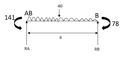


Step 4) Draw SFD and BMD
SFD
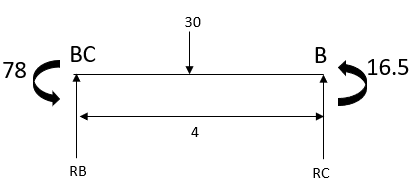
BMD
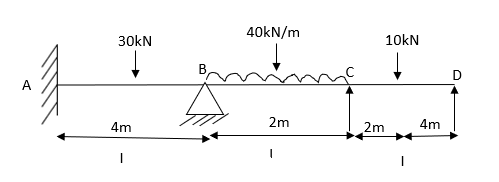
2. Analyze the given beam ABCD by Moment Distribution method
Step 1) Find fixed moment

 KNM
KNM
 KNM
KNM
 KNM
KNM
 KNM
KNM
 KNM
KNM
Step 2) Distribution factor
JOINT | MEMBER | K |
|
|
B | BA
BC
|
|
5EI | 0.2
0.8 |
C | CB
CD |
|
4.5EI | 0.89
0.11 |
Step 3) Moment Distribution
Moment Distribution Table
0.2 | 0.8 |
| 0.89 | 0.11 | ||||
Members | AB BA 15 -15
| BC CB 13.33 -13.33
| CD DC 8.89 -4.44
2.22 + 4.44 | |||||
Fixed End | ||||||||
Balancing | ||||||||
Initial Moments
Balancing | 15 -15
0.331 | 13.33 -13.33
1.34 1.98 | 11.1 0
0.25 | |||||
COF
Balancing | 0.165
-0.19
| 0.99 0.67
-0.79 -0.59 |
-0.07 | |||||
COF
Balancing | -0.09
0.058 | -0.29 -0.39
0.22 0.34 |
0.04 | |||||
Final Moments | 15.075 -14.801
| 14.8 -11.32 | 11.32 0 | |||||
 KNM
KNM
 KNM
KNM
 KNM
KNM
 KNM
KNM
 KNM
KNM
 KNM
KNM
Step 4) Draw BMD
BMD
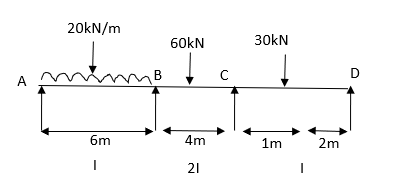
3. Analyze the given beam by M.D. method

Step 1) Find fixed end moment


Step 2) Distribution Factor
Joint | Members | K |
|
|
B | BA
BC |
|
2.5 EI | 0.2
0.8 |
C | CB
CD |
|
| 0.66
0.33 |
Step 3) Moment Distribution
Moment distribution table
0.2 | 0.8 |
| 0.66 | 0.33 | ||||
Members | AB BA | BC CB | CD DC | |||||
Fixed End | 60 -60
-60 -30
| 30 -30
| 13.33 -6.66
3.33 +6.66
| |||||
Balancing | ||||||||
Initial Moments
Balancing | 0 – 90
12 | 30 -30
48 8.8 | 16.66 0
4.40 | |||||
COF
Balancing |
-0.88 | 4.4 24
-3.52 -15.84 |
-1.92 | |||||
COF
Balancing |
1.58 | -7.92 -1.76
6.33 1.16 |
0.58 | |||||
COF
Balancing |
- 0.11 | 0.58 3.16
-0.46 -2.08 |
-1.04 | |||||
COF
Balancing |
0.20 | -1.04 -0.23
0.83 0.15 |
0.07 | |||||
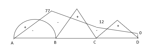
Final Moments | 0 -77.21 | 77.21 -12.64 | 12.75 0 | |||||
Step 4) Draw BMD
BMD
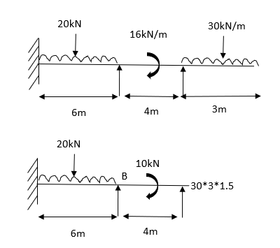
4. Analyze the given frame by MD method
Step 1) Find Fixed End Moments


Step 2) Distribution Factor
Distribution table
joint | Member | K |
|
|
B | BA |
| 1.41 | 0.47 |
| BC |
| 1.41 | 0.53 |
Step 3) Moment Distribution
Moment distribution table
0.47 | 0.53 | |||
Member | AB BA | BC CB | ||
External moment
Fixed end
Balancing |
60 - 60
| 135
2.5 -2.5
-1.25 2.5 | ||
Initial Moment
Balancing | 60 -60
27.61 | 1.25 135
31.13 | ||
COF
Balancing | 13.8 0
0 | 0
0 | ||
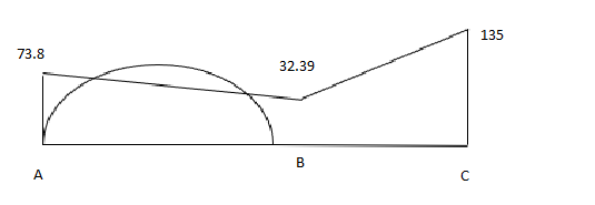
Final moments
| 73.8 -32.39 | 32.39135 | ||
BMD
Problem-based on sink
1) Analyze the given beam ABCD having pt B is sink by 10mm EI 
For AB Span 
 KNM
KNM

BC= +VE
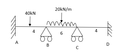


CD=0  No loading

Step 2) Distribution factors
Joint | Members | K |
|
|
B | BA
BC |
|
1.66 | 0.60
0.40 |
C | CB
CD |
|
| 0.40
0.60 |
Step 3) Moment Distribution Table
0.6 | 0.4 |
| 0.4 | 0.6 | ||||||||
Members | AB | BA | BC | CB | CD | DC | ||||||
Fixed end
Balance | 34.25
| -5.75
-28.74
| 53.66
-19.16 | -66.33
26.53 | 0
39.79 | 0
| ||||||
COF Balancing | +14.37 | -7.95 | 13.26 -5.30 | -9.58 +3.83 |
+5.74 | 19.89 | ||||||
COF Balancing | -3.97 |
-1.14 | 1.91 -0.76 | -2.65 1.06 |
1.59 |
| ||||||
COF
Balancing | -0.57 |
-0.31 | 0.53
-0.21 | 0.38
0.15 |
0.22 | 0.79 | ||||||
Final Moments | 15.34
| -43.89 | 43.89 | -46.61 | -46.61 | 20.68 | ||||||
2. Draw BMD by Moment Distribution Method and C support is sink by 25mm
For AB 


For BC  mm
mm


For CD  mm
mm


Step 2) Distribution factor
Joint | Members | K |
|
|
B | BA
BC |
|
| 0.33
0.66 |
C | CB
CD |
|
| 0.66
0.33 |
Step 3) Moment Distribution Table
0.33 | 0.66 |
| 0.66 | 0.33 | ||||||||
Members | AB | BA | BC | CB | CD | DC | ||||||
Fixed end | 40 | -40 | 149.16 | 135.83 | -40.83 42.91 | -85.83 +85.83 | ||||||
Final Balance | 40 | -40 -36.02 | 149.16 -72.04 | 135.83 -91.02 | 2.08 -45.51 | 0
| ||||||
COF Balancing | -18.01 |
15.02 | -45.51 30.04 | -36.02 23.77 |
11.89 |
| ||||||
COF Balancing | 7.505 |
-3.92 | 11.89 -7.85 | 15.02 -9.91 |
-4.957 |
| ||||||
COF
Balancing | -1.96 |
1.64 | -4.96
3.28 | -3.93
2.59 |
1.296 |
| ||||||
Final Moments | 29.28 | -63.28 | 64.01 | 36.33 | -35.20 | 0 | ||||||
Key takeaway:
Non- sway
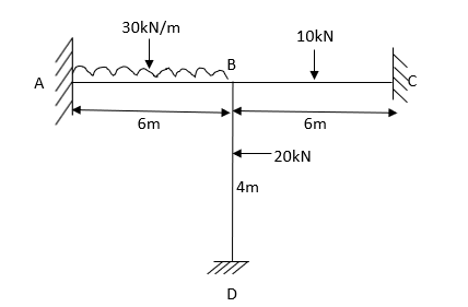
Problems:
Step 1) Fixed End Moments


Step 2) Distribution Factor
Joint | Members | K |
|
|
B | BA
BD
BC |
|
2.33 | 0.28
0.43
0.28 |
Step 3) Moment Distribution Factor
Moment Distribution Table
0.28 | 0.43 | 0.28 | ||||||
Members | AB | BA | BD | BC | CB | DB | ||
Fixed end
Balance | 90
| -90
20.3
| 10
31.17 | 7.5
20.3 | -1.5 | -10
| ||
Cot Balancing | 10.15 | 0 0 | 0 0 | 0 0 |
10.15 | 15.58 | ||
Final |
100.15 |
-69.7 |
42.17
|
27.8 |
2.65 |
5.58 | ||
Step 4) Draw BMD and SFD
BMD
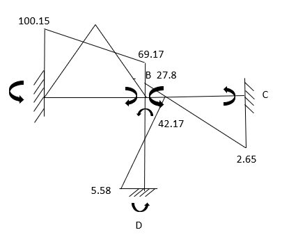
2. Determine Moments of the given figure by moment Distribution Method
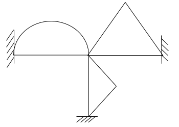
Step 1) Non-sway
Step 2) Fixed End moments

 knm
knm

Step 3) Distribution factor
Joint | Members | K |
|
|
B | BA
BC |
|
| 0.43
0.57 |
C | CB
CD |
|
| 0.64
0.36 |
Step 4) Moment Distribution Factor
Moment Distribution table
0.43 | 0.57 |
| 0.64 | 0.36 | |||||||
Members | AB | BA | BC | CB | CD | DC | |||||
Fixed end | 0 | 0 | 22.5 | -22.5 | 0
| 0 | |||||
Initial Balance | 0 | 0 -0.96 | 22.5 -1.28 | -22.5 +1.14 | 0 +0.81 | 0
| |||||
COF Balancing | -0.48 |
0.24 | +0.57 0.32 | -0.64 0.40 |
0.23 |
| |||||
COF Balancing | 0.12 |
-0.086 | 0.20 -0.114 | 0.16 -0.10 |
-0.057 |
| |||||
Final Moments | -0.36 | -0.806 | 0.806 | -3.57 | -0.637 | 0 | |||||
3. Analyses the given frame as shown. By MDM
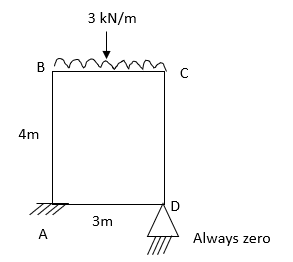
Step 1) Fixed end moment


Step 2) Distribution Factor
Joint | Members | K |
|
|
B | BA
BD
BC |
|
3.455 EI | 0.40
0.28
0.32 |
Step 3) Moment Distribution Factor
Moment Distribution Table
0.40 | 0.28 | 0.32 | |||||||
Members | AB | BA | BD | BC | CB | DB | |||
Fixed end | 106.66 | -53.33 | 10 5 | 40 20 | -40 40
| -10 +10 | |||
Initial Balance | 106.66 | -53.33 -8.66 | 15 -6.06 | 60 -6.43 | 0
| 0
| |||
COF Balancing | -4.33 | 0 0 | 0 0 | 0 0 |
|
| |||
Final Moments |
102.35
| -61.99 |
8.94 |
53.07
|
0 |
0 | |||
Step 5) Draw BMD
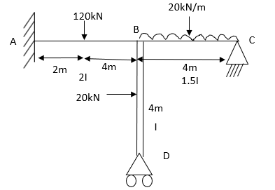
Problem-based on non-sway frame
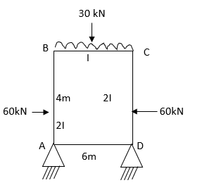
4. Analyze the non-sway frame as shown in fig. by MDM
Step 1) Fixed end moment


Step 2) Distribution factor
Joint | Members | K |
|
|
B | BA
BC |
|
| 0.70
0.30 |
C | CB
CD |
|
| 0.30
0.70 |
Step 4) Moment distribution factor
Moment Distribution table
0,70 | 0.30 |
| 0.30 | 0.70 | |||||||
Members | AB | BA | BC | CB | CD | DC | |||||
Fixed end | 30
-30 | -30
-15 | 90 | -90 | 30
15 | -30
30 | |||||
Initial
Balance | 0 | -45
-31.5 | 90
-13.5 | -90
13.5 | 45
31.5 | 0 | |||||
COF Balancing |
|
-4.72 | 6.75 -2.02 | -6.75 2.02 |
4.72 |
| |||||
COF Balancing |
|
-0.7 | 1.01 -0.3 | -1.01 0.3 |
0.7 |
| |||||
COF Balancing |
|
-0.1 | 0.15 -0.04 | -0.15 0.04 |
0.1 |
| |||||
Final Moments
|
0 |
-82.2 |
82.2 |
82.2 |
-82.2 |
0 | |||||


Step 4) Draw BMD
Key takeaway:
Steps:
Concept: The carry over  for fixed support
For Hinge support end moment 

 is not known.


Problems:
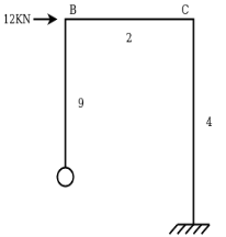
Step 1) Find Distribution Factor
Joint | Member | K | ƩK | D.F. | |
B | BA |
|
| 0.33 | |
BC |
| 0.67 | |||
C | CB |
|
| 0.67 | |
CD |
| 0.33 | |||
Step 2) Non sway moment distribution moment Table
Members | AB BA | BC CB | CD DC |
Fixed End Balancing | 0 0 0 | 0 0 0 0 | 0 0 0 |
Final Moments | 0 0 | 0 0 | 0 0 |
Step 3) Assumption For sway Frame


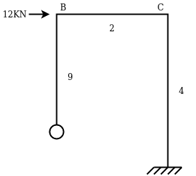
Step 4: Draw Sway Moment Distribution Table
0.33 | 0.67 |
| 0.67 | 0.33 | ||||||
Member | AB | BA
| BC CB
| CD DC | ||||||
FEM Balancing | 0 | 8 | 0 | 0 | 9 | 9 | ||||
| -2.67 | -5.33 | -6.00 | -3.00 |
| |||||
| COF Balancing |
|
1 | -3 | -2.67 |
| 1.5 | |||
| 2 | 1.78 | 0.85 |
| ||||||
| COF Balancing |
|
-0.30 | 0.69 | 1 |
|
| |||
| -0.39 | -0.67 | -0.33 |
| ||||||
| COF Balancing |
|
0.11 | -0.33 | -0.30 |
| 0.17 | |||
| 0.22 | 0.20 | 0.10 |
| ||||||
| COF Balancing |
|
-0.03 | 0.10 | 0.11 |
| 0.05 | |||
| -0.07 | -0.07 | 0.05 |
| ||||||
| 0 | 6.11 | -6.11 | -6.62 | 6.62 | 7.83 | ||||
| ||||||||||
Horizontal thrust at A 


Actual Sway force of 12 kN

Step 6) Final Moments table:
Member | AB BA | BC CB | CD DC | ||||
Non-Sway Moment | 0 0 | 0 0 | 0 0 | ||||
Sway Moment | 0 | 6.11 | -6.11 | -6.62 | 6.62 | 7.83 | |
Actual Sway | 0 | +12.98 | -12.98 | -14.06 | +14.06 | +16.6 | |
Final Moment (Addition of Non-Sway Moment +corrected moment by sway) | 0 | +12.98 | -12.98 | -14.06 | +14.06 | +16.6 | |
 Correct Horizontal A reaction

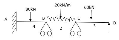
2. A two hinged portal frame ABCD consist of a vertical columns AB, DC at 4m height if the beam BC of 3m the frame carried a vertical point load of 120kN on the beam at a distance of 1m from B find the reaction at support.
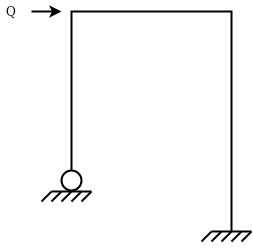
Solution:
Non-Sway analysis:
Step 1) Fixed end moment


Step 2) Draw Distribution Factor
Joint | Member | K | ƩK | D.F. |
B | BA | 3EI/L= 3EI/4 = 0.75 EI |
2.08 EI | 0.36 |
BC | 4EI/L= 4EI/3=1.33 EI | 0.64 | ||
C | CB | 4EI/L = 4EI/3=1.33EI |
2.08 EI | 0.64 |
CD | 3EI/L= 3EI/4=0.75 EI | 0.36 |
Step 3) Draw Non sways moment distribution Table
0.36 | 0.64 |
| 0.64 | 0.36 | ||||
Member | AB BA | BC CB |
| CD DC | ||||
FEM Balancing | 0 -19.2 | 53.33 -26.66 -34.13 17.06 |
| 0 0 9.6 | ||||
COF Balancing |
-3.07 | 8.53 -17.07 -5.46 10.92 |
|
6.15 | ||||
COF Balancing |
-1.96 | 5.46 -2.73 -3.49 1.75 |
|
0.98 | ||||
Final Moments | 0 -24.23 | 24.24 -16.73 |
| 16.73 0 | ||||
Horizontal reaction 

 Sway force = 1.87 kN
Sway analysis
Step 4) Initial equivalent moments are negative.
 :
: 
0.36 | 0.64 |
| 0.64 | 0.36 | ||||
Member | AB BA | BC CB |
| CD DC | ||||
FEM Balancing | 0 -10 3.6 | 0 0 6.4 6.4 |
| -10 0 3.6 | ||||
COF Balancing |
- 1.15 | 3.2 3.2 -2.05 -2.05. |
|
-2.05 | ||||
COF Balancing |
0.35 | - 1.03 -1.03 0.66 0.66 |
|
0.35 | ||||
Final Moments | 0 -7.2 | 7.2 7.2 |
| -7.2 0 | ||||
Horizontal reaction 

Resolving force horizontally = 1.81 +1.81 =3.63kN
Actual Sway = 3
Sway 0 7.27 | 7.27 7.27 | -7.27 0 |
| +3.64 3.64 | -3.64 0 |
Non-Sway 0 21.17 | -21.17 21.17 | -21.17 0 |


Analysis of frame with sway
3. Analyses the rigid frame shown in fig by M.D. method.
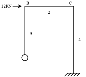
Step1) Fixed end moment
Fixed end moment in all the members = 0
Step 2) Distribution factor
D.F
B | BA |
|
| 2.33EI | 0.57 |
BC |
|
| 0.43 | ||
C | CB |
|
| 2.5EI | 0.4 |
CD |
|
| 0.6 |

Conclude S = 80 kN

Sway Force
Consider FBD for column


SWAY ANALYSIS
Consider Sway on right hand side
 is
is 
 is
is 


Consider 
Moment distribution maybe carried out.
A B C D
10 | 0.5 10 | 0.5
| 0.5
| 0.5 20 |
20 |
| -5 | -5 | -10 | -10 |
|
-2.5
|
2.5 | -5 | -2.5 |
| -5 |
2.5 | 1.25 | 1.25 |
| ||
1.25
|
-0.32 | 0.63 | 1.25 |
| 0.63 |
-0.32 | -0.62 | -0.62 |
| ||
-0.16
|
+0.16 | -0.31 | -0.16 |
| -0.31 |
0.16 | 0.08 | 0.08 |
| ||
0.08
|
-0.02 | 0.04 | 0.08 |
| 0.04 |
-0.02 | -0.04 | 0.04 |
| ||
+8.67 | -7.32 | -7.32 | -10.66 | 10.66 | 15.35 |


Sway Correction Factor 


Arbitrary Sway | +8.67 | +7.32 | -7.332 | -10.66 | +10.66 | +15.37 |
Actual Sway | 8.67×6.37= 53.88 | 7.3×6.2= 45.44 | -45.44 |
|
|
|
Non-Sway | +20.42 | -12.44 | +12.44 | +3.35 | -3.35 | -1.77 |
Final | +74.30 | +33.05 | -33.05 | -62.75 | +62.7 | +93.62 |
Key takeaway:
Step 1) Fixed end moment
Step 2) Distribution factor
Step 3) Moment Distribution factor
Step 4) Draw BMD and SFD
References:
1. Structural Analysis: Deodas Menon---Narosa Publishing House.
2. Structural Analysis: Thandavamoorthy---Oxford University Press.
3. Structural Analysis: A Matrix Approach by Pundit and Gupta, McGraw Hills.
4. Structural Analysis by Hibbler, Pearson Education.
5. Structural Analysis: M. M. Das, B. M. Das---PHI Learning Pvt Ltd. Delhi.
6. Fundamentals of Structural Analysis: 2nd ed---West---Wiley.
7. Theory of Structures: Vol. I & II by B. C. Punmia, Laxmi Publication.
8. Theory of Structures: Vol. I & II by Perumull & Vaidyanathan, Laxmi Publication.
9. Fundamentals of Structural Analysis: K. M. Leet, Vang, Gilbert—McGraw Hills
10. Matrix Methods for structural engineering. by Gere, Weaver.
11. Introduction to the Finite element method, Dr. P.N. God bole, New Age Publication, Delhi.
12. Finite element Analysis, S.S. Bhavikatti, New Age Publication, Delhi.
13. Basic Structural Analysis: Wilbur and Norris.


