Unit - 6
Plastic analysis of structure
1. Plastic Theory
Plastic analysis will be introduced that behavior of steel beams & frames in the plastic range.
2. Terminology
Plasticity – It is defined as the state of permanent deformation without fracture in a material caused by the stresses which are greater than the yield stresses.
Plastic -Hinge – when the entire c/s of the beam becomes fully plastic on infinitely small increased in applied moment would cause large increases in curvature this effect is plastic hinge.
Plastic moment – The bending moment required to develop of plastic hinge is known as plastic moment. Denoted by Mp
Plastic collapse – It is also called collapse mechanism it is a condition of which the indefinite deflection occurs of construction load
Plastic collapse level – The load at which plastic collapse occurs is the plastic load it denoted by wu.
Load factor – It is the ratio of the collapse load to the working load.
It is assumption of plastic theory.
Diagram
A = Limit of proportionality
OA Elastic range
B = Upper yield point
AB Plastic range
C = Lower yield point
CD= Plastic range
E = Ultimate stress point
F = Breaking point
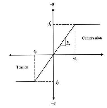
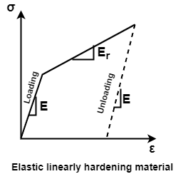
Since it is very difficult and complicated to calculate moments from the actual / True stress-strain curve and also strength calculated is on lower side, therefore the stress-strain curve is idealized in the plastic analysis.
In the plastic analysis, the elastic limit and lower yield point may be assumed to be numerically identical (i.e., OABC becomes OA). Because of large reserve strength (ductility) in mild steel plastic range is to extend it without limit by neglecting the effect of strain hardening. (i.e., CDEF becomes AB).
IS 800 2007 (Indian standard code for design of steel structures) has laid down a few requirements of steel to satisfy plasticity in the material. These are as follows:
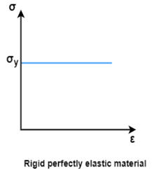
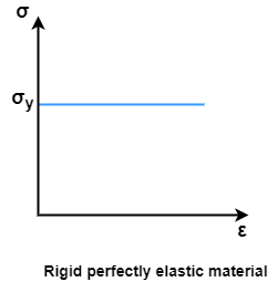
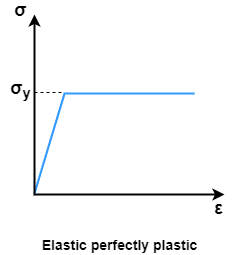
Consider a rectangular beam width of b and depth d subjected to steadily increasing load w over a simply supported span l
Stress stain diagrams shows elastic stress distribution for working and service load hence 
Where f= working stress
Further increases in load caused stress level fy at extreme fiber as shown in fig. this is the limit of elasticity
Therefore, elasticity moment of resistance 

For rectangular section 
Further increases in load a does not produce increase in stress as fy remains constant as per idealize stress strain curve but strains increase thus stress is in the fiber immediately below the extreme fiber now reaches to fy
Yielding penetrated inside the fiber this is called elasto plastic range
Further increase in load causes yielding inside the cross section over the depth and the stress distribution is rectangular in both compression as well as tension this stage is known as fully plastic range and the moment at this stage is called plastic range
Moment at fully plastic stage is given by


For rectangular section C = total compressive force
= 
T= total tensile force= 
a = lever arm (y1+y2)
For rectangular section


Where Zp= plastic sectional modulus = 
Concurrently yielding also penetrated is adjoining cross section on either side
Here section
EE fully elastic range/stage
DD elasto plastic range /stage
CC fully plastic range/stage
When yielding of section takes place over entire depth
Section CC behaves similar to mechanical hinge called plastic hinge but at this plastic hinge moment is constant and it is denoted by Mp
Excessive rotation at C due to deformation of plastic hinge transform structure in to mechanism called as collapse mechanism. At this stage load w reaches to wp is called plastic collapse load


Now,
it is seen that rectangular section using equation

Thus, the plastic stage rectangular section has 50% more strength compare to that of elastic stage.
Example
A S.S. Beam is determinate she. Formation of one hinge in the beam created collapse mechanism since, the maximum moment under the load the hinge will form at the place.
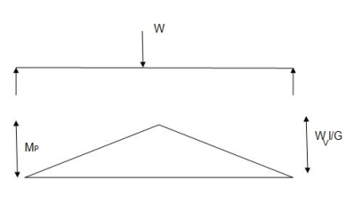


1. Static method
Example
Determine the collapse load Wu in the simply supported beam subjected to concentrated point load at center
Solution:
As simply supported beam is a determinate structure formation of one hinge in the beam creators collapse mechanism since the moments is maximum under the load the hinge will form at that place


2. Kinematics method (upper bound theorem)
This termed is also called as mechanism method using principle of virtual load is equal to the work absorbed in the plastic hinges
Work done due to external load= work absorbed by plastic hinge

Important points
At each plastic hinge, work absorbed must be positive (Neglect the sign conventions).
Location of plastic hinges (N) in a
a) Fixed support
b) Rigid joint beam at a
c) Interior support
d) Concentrated point load
Plastic hinge at simple, roller and hinge support as well as at free not possible
If an indeterminate structure has redundancy 'r', the insertion of 'r' plastic hinges makes it statically determinate. Any further increase hinge converts the structure in to collapse mechanism. Hence number of plastic hinge required to collapse + 1
n = r+1 (v) the possible independent mechanisms are found N' = N-r.
Where
N-Number of plastic hinge developed (locations)
r- redundancy or degree of static indeterminacy
Partial collapse occurs when N<n i.e., N< (r + 1) In such case, part of structure may fail whole structure.
Complete collapse occurs when N = n.
In such case mechanism has only one dof.
Over-complete collapse - N>n i.e., N> (r+ 1)
In such case, there are two or more mechanisms for which the corresponding value of the load is same.
Problems: (Kinematical method)
Steps:
Example:1]
Determine collapse loud Wn at S. S. end moment is not issued plastic hinge in zero

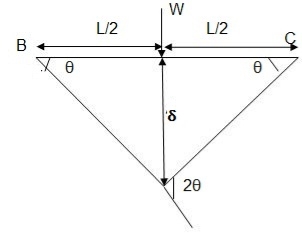
By virtue work
External loud = internal loud
Wu x S = Mp (Q + Q)
Wu X
Wu= 
Example:2]
Determine collapse loud Wu of 2.8 to eccentric load

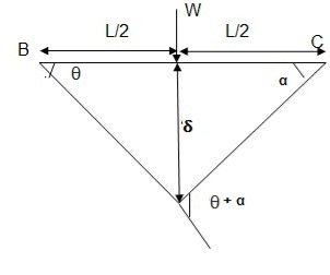
E Wu s S = E Mp
Wu S = Mp (+  )
)
= 
S = a S = 


Wu x a = Mp 
Wu a = Mp 

Mp =
 Collapse load
Example: 3]
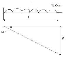
Determine collapse load (Wu) of a simply supported beam subjected to UDL over span
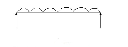
Solution:


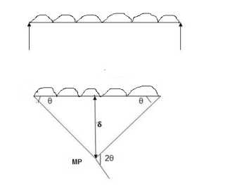
Standard cases for cantilever beam
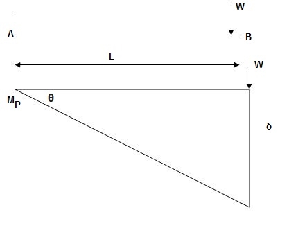


2. Determine collapse load Wu


1. Static or Lower Bound Theorem
It states that the if a bending moment distribution can be found which satisfy conditions of equilibrium and yield then the corresponding load must be less than or equal to the true collapse load. This theorem is not much useful and convenient for plastic analysis.
2. Kinematic or Upper Bound Theorem
It states that the collapse load obtained from any assumed mechanism for a given structure must be either greater than or equal to the true collapse load. Here the equilibrium condition is satisfied but not yield condition hence this theorem is called unsafe theorem
3. Uniqueness Theorem
It states that if a bending moment distribution can be obtained which satisfy the three conditions of mechanism, equilibrium and yield, then the collapse load corresponding to such bending moment distribution will be the true collapse load.
1. Plastic sectional modulus:
It is defined as a first moment area about equal area axis

2. Plastic moment:

For rectangular section


Where Zp= plastic sectional modulus = 
3. Shape factor:
It is ratio of plastic moment carrying capacity (Mp) to the yield moment (Me) of a section.

Shape factor –
It is defined as the of plastic moment of a section to the yield moment of the section
S =  =
=  =
= 
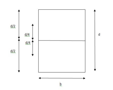
S = 
Zp = 
= 
= 
Z = 
S = 
 = 1.5
= 1.5
Shape factor of 1.5 Rectangular
2. Shape factor of Diamond section
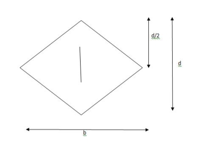
S = 
Zp = 
= 
= 
Shape factor= 2 for Diamond
3. Shape factor for Triangle
Z =  =
= 
 =
= 
Diagram
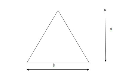
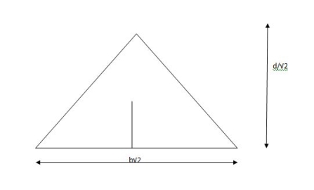
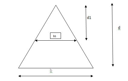
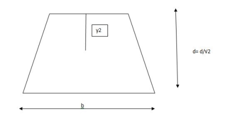
y2 = 

y2 = 0.1553
Zp =  ( y1 + y2)
= 
Zp = 
S=  = 2.346
Shape factor of triangle = 2.346
4. Shape factor for circular section
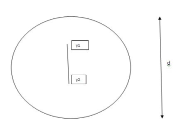
S = 
Z=  =
= 
 =
= 
ZP = 
= 
 =
= 
Examples
1. Determine load (Wu) using mechanism method of a simply supported beam subjected to point load at centre.

Solution:


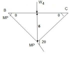
2. Determine collapse load (Wu) of a simply supported beam subjected to eccentric load.

Solution:


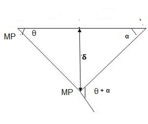
Using virtual work principle


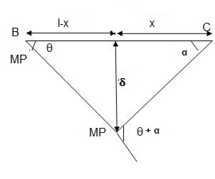
3. Determine collapse load of a simply supported beam subjected to udl over span.

Solution:

Average deformation
But 


B. Plastic analysis of indeterminate beams
Examples:
1. Determine true collapse load of a propped cantilever beam subjected to load at centre.
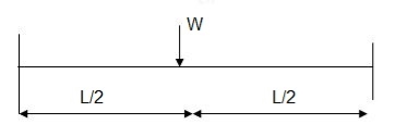
Solution:

But

2. Determine true collapse load of a fixed beam subjected to udl

Solution:


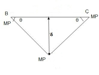
Where Wu= W.L = total UDL
Example:1]
The fig shoes a rectangular portal frame whose legs are fixed at base. The frame carries a point load W at mid span and a horizontal sway load W/2 Find the value of W at which the frame will collapse all the members are of the same section.
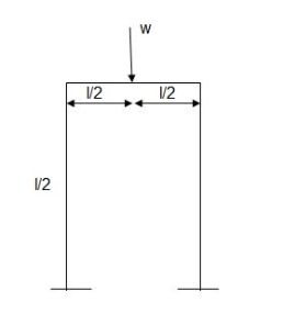
Solution:
Use of virtual work equation


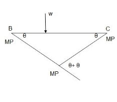
Sway Mechanism


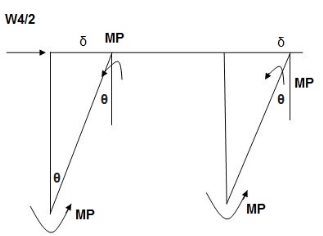
Combined mechanism:


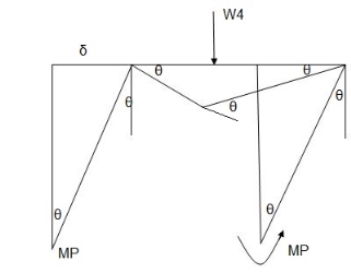
Example: 2]
Determine the value of fully plastic moment of the frame when loaded up to collapse as shown in fig. the plastic moment of frame is uniform throughout
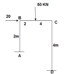
Solution:
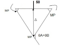
Beam mechanism:


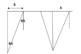
Sway analysis




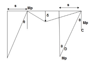
Combined loading



References:

