Back to Study material
S

Unit - 1

Compass and Levelling


  • Surveying is the art of determining the relative positions of different objects on the surface of the earth.
  • Importance of Surveying:

  • The making plans and layout of all Civil Engineering initiatives inclusive of creation of highways, bridges, tunnels, dams and many others are primarily based totally upon surveying measurements.
  • Moreover, for the duration of execution, challenge of any importance is built alongside the strains and factors set up with the aid of using surveying.
  • Thus, surveying is a simple requirement for all Civil Engineering initiatives.
  • Other major works wherein surveying is frequently utilised are:
  • to repair the countrywide and kingdom boundaries;
  • to chart coastlines, navigable streams and lakes;
  • to set up manage factors;
  • to execute hydrographic and oceanographic charting and mapping; and
  • to put together topographic map of land floor of the earth.
  • Key Takeaways:

    Surveying is the art of determining the relative positions of different objects on the surface of the earth.


    There are two aspects:

    1. Location of a point by measurement from two points of reference

  • According to this principle, the relative position of a point to be surveyed should be located by measurement from at least two points of reference, the positions of which have already been fixed.
  • 2. Work from whole to part:

  • According to this principle, it's far constantly suitable to carryout survey paintings from entire to part. This means, whilst a place is to be surveyed, first a device of manipulate factors is to be mounted overlaying the entire location with very excessive precision. Then minor information is placed with the aid of using much fewer particular methods. The concept of running this manner is to save you the buildup of mistakes and to manipulate and localize minor mistakes which, otherwise, could increase to more magnitudes if the opposite method is followed, for this reason making the paintings out of control on the end.
  • Key Takeaways:

    There are two aspects:

    1. Location of a point by measurement from two points of reference

    2. Work from whole to part:


    Surveying:

  • It is the art of determining the relative positions of different objects on the surface of the earth.
  • Object of Surveying:

  • To prepare a map to show the relative position of the objects on the surface of the earth.
  • The map is drawn to some suitable scale.
  • It shows the natural features of a country.
  •  


    There are two types of surveying:

    Plane Surveying:

  • The curvature of the earth is not taken into consideration.
  • It is carried out for small area.
  • Plane surveying is conducted by state agencies.
  • It is carried out over an area less than 250 km².
  • Geodetic surveying:

  • The curvature of the earth is taken into consideration.
  • It is carried out for large area.
  • Geodetic surveying conducted by survey of India Department.
  • It is carried out over an area greater than 250 km².
  • Key Takeaways:

    There are two types of surveying:

  • Plane Surveying
  • Geodetic surveying
  •  


    The ratio by which actual length of the object is reduced or increased is known as scale.

    Types of scale:

  • Full size scale
  • Reducing scale
  • Increasing or Enlarging scale
  • 1. Full size scale:

  • If the actual length of the object is shown on the drawing.
  • 2. Reducing scale:

  • If the actual length of the object is reduced in order to accommodate it on the drawing sheet the scale is said to be a reducing scale.
  • 3. Increasing or Enlarging scale:

  • If the actual length of an object is enlarged so as to bring out its details more clearly on the drawing, the scale used is said to be increasing scale.
  • Key Takeaways:

    There are three types of scale:

  • Full size scale
  • Reducing scale
  • Increasing or Enlarging scale
  •  


  • The process of establishing intermediate points on a straight line between two end points is known as ranging. It is done before a survey line is chained. It consists of two methods:
  • Direct
  • Indirect or reciprocal method.
  • Direct method: when intermediate rainging rods are fixed on a straight line by direct observation from end stations, the process is known as direct ranging
  • Indirect ranging method: when the end station is not intervisible due to being high ground between them, intermediate ranging rods are fixed on the line in an indirect way this method is known as indirect ranging.
  • Key Takeaways:

    The process of establishing intermediate points on a straight line between two end points is known as ranging


  • A chain is prepared with 100 or 150 pieces of galvanised mild steel wire of 4mm, the end of the pieces are bent to form loop and then the pieces are connected to get with the help of 3 oval rings. Which make the chain flexible. Two brass handles are provided at the two ends of the chain. Tallies are provided at every 10 or 25 links.
  • Metric chain
  • Steel Band
  • Engineer's chain
  • Gunter's chain,
  • and Revenue chain
  • Metric chain:

  • Metric chains are available in lengths of 20m and 30m. The 20m chain is divided into 100 links, each of 0.2m. Tallies are provided at every 10 links (2m). This chain is suitable for measuring distances along fairly level ground.
  • Steel Band:

  • It consists of a ribbon of steel of width 16mm and of length 20 or 30m. It has a brass handle at each end. It is graduated in meters, decameters, and centimeters on one side and has 0.2m links on the other. The steel band is used in projects where more accuracy is required.
  • Engineer's chain:

  • The engineer's chain is 100 ft long and is divided into 100 links. So, each link is of l ft. Tallies are provided at every 10 links (10 ft), the central tally being round. Such chains were previously used for all engineering work.
  • Gunter's chain:

  • It is 66 ft long and divided into 100 links. So, each link is of 0.66. It was previously used for measuring distances in miles and furlongs.
  • Revenue chain:

  • The revenue chain is 33 ft long and divided into 16 links. It is mainly used in cadastral survey.
  • Key Takeaways:

    There are five types of chain:

  • Metric chain
  • Steel Band
  • Engineer's chain
  • Gunter's chain,
  • and Revenue chain
  •  

     1.8 Offsetting:

  • The lateral measurement taken from the object to the chain line is called offset.
  • There are two types of offsets:
  • Perpendicular offset
  • Oblique offset
  •  


  • A traverse is a series of connected lines whose lengths and directions are to be measured and the process of surveying to find such measurements is known as traversing.
  •  


  • Prismatic compass is used for angular measurements of angles between two or more relative points in horizontal plane.
  • The prismatic compass is a portable form of magnetic compass which is installed on a tripod stand by which angles are measured in horizontal plane.
  • The main parts of the prismatic compass are shown below:
  • H:\unit 1 survey\IMG_20210525_193132.jpg

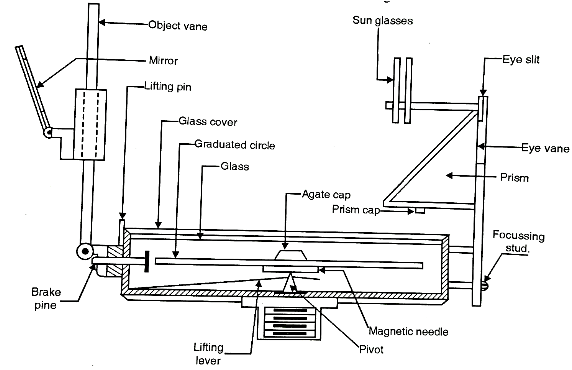
    Fig.1.1: Prismatic Compass

    1. Pivot:

  • Pivot is made of hard steel material. It is fixed at the centre and on which magnetic needle with graduated circle can be balanced.
  • 2. Lifting lever:

  • To prevent undue wear, the needle when not in use should be lifted off the pivot by means of lifting lever.
  • 3. Brake pin:

  • When brake pin or knob pressed gently, it touches the edge of the graduated ring in order to bring it rest and thus damp the oscillations of the graduated ring and give the easy way to take the accurate reading.
  • 4. Reflecting mirror:

  • Reflecting mirror is an adjustable mirror which can be made to incline of any angle that object too high or too low may be sighted by reflection.
  • 5. Sun glasses:

  • Sun glasses are attached to the frame of reflecting prism which can be interposed into the line of sight, when the sun or other luminous objects are to be sighted.
  • 6. Glass prism:

  • Looking through the prism, the observer can see the graduation erect and magnified and hence bearing of the line can properly and accurately be taken.
  • 7. Aluminium ring:

  • Graduation from 0° to 360° are marked on aluminium ring which helps in taking reading of bearing of line.
  • Procedure for using the Prismatic Compass:

  • It is noted that all the angles measured with prismatic compass are with respect to north i.e., magnetic meridian. The following are the temporary adjustments usually necessary before using prismatic compass on field.
  • Fixing the compass in tripod:

  • In field work, the prismatic compass is first of all fixed on the top of tripod by a ball and socket arrangement.
  • Centering:

  • Centering is the process in which the compass is to be kept exactly over the station from where the bearing is to be determined.
  • The centering is checked by dropping a small pebble or stone from the underneath of the compass.
  • If the stone falls on the top of peg, then centering is correct, if not, then the centering is corrected by adjusting the legs of the tripod.
  • Levelling:

  • Levelling of the compass is done with the aim to freely swing the graduated circular ring of the prismatic compass.
  • The ball and socket arrangement on the tripod will help to get a proper level of the compass.
  • Observing the bearing of a line:

  • It is noted that all the angles measured with prismatic compass are with respect to north i.e., magnetic meridian.
  • Bearing of a line:

  • The horizontal angle made by a survey line with reference to magnetic north in a clockwise direction is called as the bearing of a line.
  • Consider a line AB of which the magnetic bearing is to be observed.
  • Note that a line AB is a line between the station points i.e. A and B on ground.
  • Let the ranging rod be fixed at B and the compass is centred on A. Turn the compass in the direction of line AB.
  • When B is bisected by the vertical hair i.e., ranging at B comes in the line with the slit of eye vane and the vertical hair of the object vane as shown in Fig. 1.12.3(a); then reading under the hair through prism is taken, which gives the bearing of line ABT
  • For understanding purpose, in Fig. reading of bearing line AB is 25° 30'. Hence bearing of a line AB with respect to north is 25° 30' as shown in Fig.
  • H:\unit 1 survey\IMG_20210525_193223.jpg

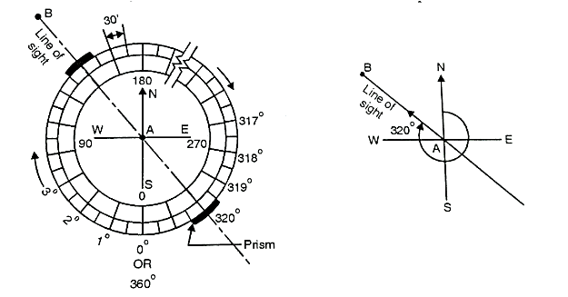
    Fig.1.2: Graduations in Prismatic Compass

    Key Takeaways:

    Prismatic compass is used for angular measurements of angles between two or more relative points in horizontal plane. The prismatic compass is a portable form of magnetic compass which is installed on a tripod stand by which angles are measured in horizontal plane.


  • The horizontal angle made by a survey line with reference to magnetic north pole in a clockwise direction is called as the bearing of a line.
  • Types of bearings:

  • Generally, the bearings of survey lines are designated in the following two types:
  • Whole circle bearing (W.C.B.) system
  • Reduced bearing (Quadrantal) system
  • 1. Whole circle bearing (W.C.B.) system:

  • When the bearing of a line is measured with respect to magnetic north in clockwise direction, it is called as magnetic bearing or whole circle bearing.
  • The value of W.C.B. varies from 0° to 360°.
  • Four quadrants I, II, III and IV are shown in Fig.
  • The W.C.B. of a line OA in the first quadrant is
    (
    between 0° to 90°).
  • The W.C.B. of a line OB in the second quadrant with respect to north is
    (
    between 90° and 180°) W.C.B. of a line OC in the third quadrant with respect to north is
    (
    between 180° and 270°) and W.C.B. of a line OD in the fourth quadrant with respect to north is
    , (
    between 270° and 360°).
  • H:\unit 1 survey\IMG_20210525_193256.jpg

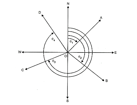
    Fig.1.3: Whole Circle bearing

    2. Reduced bearing (Quadrantal system):

  • In reduced bearing, the bearing of survey lines is measured with respect to north and south line either in clockwise or anticlockwise direction towards east or west.
  • Fig. shows quadrantal bearing system.
  • Any line in any of the four quadrant is expressed by an angle which is measured from either north or south.
  • The directions are essentially written before and after the value of angle.
  • This helps to identify in which quadrant the lines lie. The maximum bearing in such case is 90°.
  • H:\unit 1 survey\IMG_20210525_193316.jpg

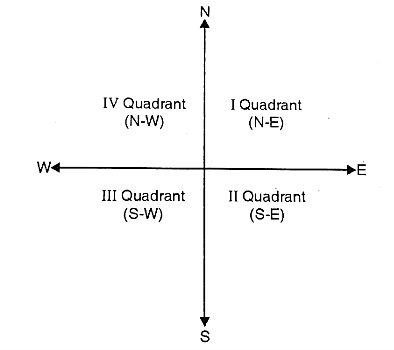
    Fig.1.4: Quadrantal bearing


    Key Takeaways:

    Generally, the bearings of survey lines are designated in the following two types:

  • Whole circle bearing (W.C.B.) system
  • Reduced bearing (Quadrantal) system
  •  


  • The reference line with respect to which horizontal angle of survey line is measured, known as meridian.
  • Types of meridians:

    a)     True Meridian: The line or length passing through the geometrical north pole, geographical south pole and any point on the earth surface is known as true meridian.

    b)    Magnetic Meridian: It is the direction indicated by freely suspended and balanced magnetic needle unaffected by local attractive forces. The location of magnetic pole is continuously changes hence, the direction of magnetic also changes.

    c)     Arbitrary Meridian: It is any convenient direction usually from survey station to some well-defined permanent object. This is used for small area survey or to determine the relative direction of small traverse.

    Key Takeaways:

    There are three types of meridian:

  • True meridian
  • Magnetic meridian
  • Arbitrary meridian
  •  


  • When the suspended magnetic needle will point towards the north direction (magnetic meridian);
  • But if the compass is centered nearby iron or steel structure or electric cable line such as LT. line or transmission tower, lamp post carrying high voltage, steel button of shirt or freely steel wrist watch, bunch of keys, steel tape etc.
  • Then it is observed that the magnetic needle of prismatic compass will not point exactly towards north but will deflect from its normal position.
  • In short, the magnetic needle is under the influence of some external forces causing the deflection of needle from its normal position and showing some error in bearings of lines.
  • Therefore, it is concluded that the deviation of the magnetic needle from its normal position (North direction) under the influence of external forces is called as local attraction.
  • Local attraction shows some error in bearings of lines, therefore while selecting the stations for compass survey, objects made up of steel shall possibly be avoided.
  • Detection of Local Attraction:

  • The presence of local attraction can be detected or identified by observing the difference between the observed fore bearing (F.B.) and back bearings (B.B.) of each line.
  • If the difference between F.B. and B.B. is not exactly 180°, then the stations on the both sides of a line are affected by local attraction.
  • If the difference between F.B. and B.B. is exactly 180°, then the stations on both the sides of a line are free from local attraction, or the amount of local attraction at both stations is same.
  • Note: If F.B.-B.B. = 180°; free from local attraction / same local attraction.

    If F.B.-B.B. 180°; affected by local attraction.

    Effect on included angle:

  • After plotting the close traverse from observed F.B. and B.B. readings, total sum of the internal included angles of the traverse is not equal to the correct sum of the internal included angles of that traverse [i.e. (2n 4) x 90° where n number of sides of traverse] due to error caused by local attraction.
  • In short, an included angle is not correct on measurement due to local attraction and some adjustment is required to be done to compensate the error.
  • Adjustment of Local Attraction or Eliminating the Effect of Local Attraction:

    There are two methods by which the effect of local attraction can be eliminated or can be adjusted.

    Method I:

  • In this method, the difference in fore bearings (F.B.) and back bearings (B.B.) of all the survey lines of the traverse are observed.
  • If for the line, difference between F.B. and B.B. is exactly equal to 180°, then this line is selected and the process of applying correction is started from bearings of this line itself and then corrections are applied to the observed bearings of other lines.
  • It is noted that, if the observed bearing is less than the corrected bearing, the error is negative and correction applied to the bearing is positive.
  • If the observed bearing is more than the corrected bearing the error is positive and correction applied to the bearing is negative.
  • Method II:

  • In this method, the included angles between the lines are calculated at all the stations. If the traverse is of closed type, the sum of the internal included angles must be equal to (2n-4) x 90° where n is number of sides of the closed traverse.
  • If there is any discrepancy in the total of the included angles, then discrepancy or error is distributed equally to all the angles.
  • When all the angles are corrected then, difference between F.B. and B.B. of each line is found to be 180°.
  • This method is based on the fact that the included angles calculated from incorrect bearings will be correct, since the amount of error is same for all the bearings at the station.
  • Key Takeaways:

    The deviation of the magnetic needle from its normal position (North direction) under the influence of external forces is called as local attraction.


  • The horizontal balanced position of the magnetic needle gets disturbed due to the magnetic influence of the earth. The needle dips on one of its sides towards the pole. The angle which the deflected needled makes with horizontal is known as dip of the magnetic needle.
  • The needle is brought to its horizontal position by attaching a small weight called rider to the higher side of the magnetized needle.
  • H:\unit 1 survey\IMG_20210525_193334.jpg

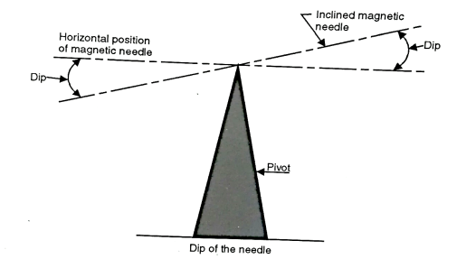
    Fig.1.5: Dip of the needle

    Key Takeaways:

    The angle which the deflected needled makes with horizontal is known as dip of the magnetic needle.


  • The magnetic meridian and true meridian are same only at few places, whereas at other places they do not coincide. The horizontal angle between the true meridian and magnetic meridian at a place is known as 'magnetic declination".
  • The magnetic meridian may fall on either east or west of true meridian and accordingly the declination is said to be 'East' or 'West' as shown in Fig.
  • H:\unit 1 survey\IMG_20210525_193409.jpg

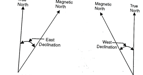
    Fig.1.6: East and West declination respectively

    Determination of Declination:

    The methods commonly adopted for determining magnetic declination are:

    1. By observation to sun:

  • The bearing of line with respect to true north can be determined by taking observation to the sun and then its magnetic bearing is observed by a prismatic compass. When the true meridian and magnetic meridian of a line is known is declination can be observed by relation.
  • True bearing- magnetic bearing= Declination.
  • 2. By isogenic charts:

  • An 'isogenic line' is a line joining the points having same declination. The line joining points of zero declination is called 'agonic line'. The Govt. publishes these isogenic charts.
  • Key Takeaways: 

    The horizontal angle between the true meridian and magnetic meridian at a place is known as 'magnetic declination".


    Q. A line was drawn to magnetic bearing of 238° 20' on an old map when mag. 5°40’ E. To What bearing it should be set now if present magnetic declination is 3° 10' W

    True bearing of line = magnetic bearing Declination = 288°20'+ 5°40’=244 °

    Now, declination is 3°10' W

    Bearing = 244°--3°10’=240°50’

    Q. The magnetic bearing of sun at noon is 356° 30' Find the declination.

    True bearing = mag. bearing ± Declination

    360° =356° 30’Dectination.

    Declination = 3°30' E


    The accessories of plane table are:

    H:\unit 1 survey\IMG_20210525_193438.jpg

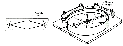
    Fig.1.7: Trough and Circular Compass

    A trough compass or circular box compass:

  • These compasses are used to mark north direction on the drawing sheet.
  • A plumbing fork or U frame:

  • It is used for centering the table.
  • H:\unit 1 survey\IMG_20210525_193459.jpg

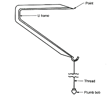
    Fig.1.8: Plumb bob with U frame

    A bubble tube or spirit level:

  • If bubble tube is not fitted to aliased, the separate bubble tube is used for leveling the table.
  • H:\unit 1 survey\IMG_20210525_193524.jpg

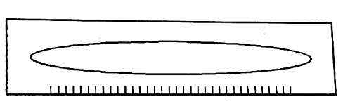
    Fig.1.9: Spirit level

    A water proof cover:

  • It is used to protect the sheet from rain.
  • Drawing sheet:

  • Drawing sheet should be of best quality.
  • It should be never be folded or rolled but should be carried flat.
  • To reduce the strain on the eyes, the sheet should be of faint colour.
  • Zinc or celluloid sheets are used for plane tabling in damp climates.
  • Sheet should be properly stretched on drawing board with clips or by pasting the edges of sheets.
  • Other drawing materials:

  • Other drawing materials required are pins, pencils, rubber, scales etc.
  • Key Takeaways:

    The accessories of plane table are:

  • A trough compass or circular box compass
  • A plumbing fork or U frame
  • A bubble tube or spirit level
  • A water proof cover
  • Drawing sheet
  • Other drawing materials
  •  


  • It is most suitable for survey of details between stations which have already been fixed by theodolite or any other accurate method of surveying.
  • It is commonly employed for small and medium scale mapping of comparatively large areas where great accuracy is not the main consideration such as for topographical surveys.
  •  


    Advantages:

  • It is rapid and suitable for small scale maps.
  • Since field work and plotting work is carried out simultaneously. The surveyor can compare the plotted work with the actual features of the area.
  • Recording the readings is seldom required and hence these are no chance of mistakes in recording.
  • No greater skill is required to prepare satisfactory map.
  • It is most suitable for the areas where the compass survey cannot be done due to local attraction.
  • Check lines detects the errors of measurements and plotting on field itself.
  • It is less costly.
  • The office work consists of only finishing of drawings.
  • Disadvantages:

  • Plane table is unsuitable for work in wet climate and in high wind.
  • It is inconvenient to replot the survey to different scale and to compute the quantities, when proper field notes are not available.
  • Plane table is only suitable for open country.
  • It is not intended for greater accuracy.
  • Instrument is heavy.
  • Number of accessories are to be carried and being loose may get lost.
  • In bright sun, due to the strain on eyes, plotting becomes difficult.
  •  


  • The degree of precision to be attained in plane tabling depends upon the character of the survey, the quality of the instrument, the system adopted and upon the degree to which accuracy is deliberately sacrificed for speed.
  • The various sources of errors may be classified as:
  • 1. Instrumental Errors:

  • Errors which are included due to the bad quality of instruments.
  • 2. Error due to Manipulation and Sighting: These includes-

    (a) Non-horizontality of board.

    (b) Defective sighting.

    (c) Defective orientation.

    (d) Movement of board between sights.

    (e) Defective or inaccurate centering.

    (a) Non-horizontality of board:

  • When the difference in elevation between the point sighted is more, then the effect of non-horizontality of board is more severe.
  • (b) Defective Orientation:

  • The accuracy of work of plane table mapping largely depends upon the precision with which points are sighted.
  • The telescopic alidade is superior than plain alidade, as in case of telescopic alidade the line of sight is definite.
  • (c) Defective Orientation:

  • Orientation done with magnetic meridian method is unreliable, because of local attraction possibility. When there is erroneous orientation, it contributes towards distortion of the survey.
  • In order to avoid such errors, orientation should be checked at as many stations as possible by sighting distant prominent objects already plotted.
  • (d) Movement of board between sights:

  • The table may be disturbed between any two sights, due to the carelessness of observer, which may result in the disturbance of orientation. To reduce the possibility of such movement, the clamp should be firmly applied.
  • In order to avoid error due to the movement of board, it is always advisable to check the orientation at the end of the observation from a station.
  • (e) Inaccurate Centering:

  • It is very essential to have a proper conception of the extent of error introduced by inaccurate centering, as it avoids unnecessary waste of time in setting up the table by repeated trials.
  • Key Takeaways:

    There are two types of errors:

  • Instrumental Errors
  • Error due to Manipulation and Sighting
  •  


    1.21.1 Radiation:

    H:\unit 1 survey\IMG_20210525_193612.jpg

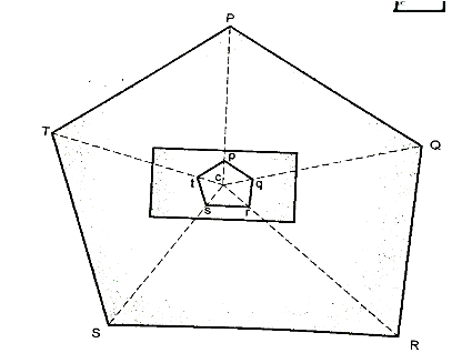
    Fig.1.10: Resection Method

    Procedure:

  • Select an instrument station C from which all the points to be surveyed are visible.
  • Set up and level the board and clamp it.
  • Select a point C, on the sheet to represent the instrument station.
  • Draw the direction of the magnetic meridian with the help of trough or circular compass in the top corner of sheet.
  • With alidade touching C, sight various points P.Q.R.S.T etc. to be located, draw rays towards them
  • Measure the distance CP, CQ, CR, CS, CT etc. and plot them to scale and join the points pqrst so obtained.
  • Use:

  • This method is used for small area which can be commanded from a single
  • This method is employed in combination with some other method.
  • 1.21.2 Intersection method:

  • In intersection method the point is fixed on plan by the intersection of the rays drawn from the two instrument stations.
  • H:\unit 1 survey\IMG_20210525_193643.jpg

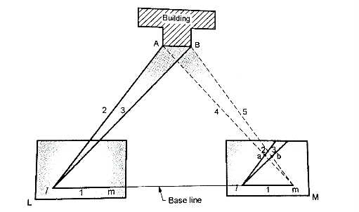
    Fig.1.11: Intersection method

    Procedure:

  • Select two points L and M in a commanding position.
  • The line joining the station L and M is known as base line.
  • Measure the base line LM.
  • Set up the table at the sta L and mark point I on sheet over L.
  • Orient the board by placing alidade along Im and turn the board until the ranging rod at B is bisected. Clamp the board.
  • With alidade touching point I draw rays 1, 2, 3 of indefinite length as shown in Fig.
  • The table is then shifted to station M, orient it by backsighting method on L.
  • Through m draw rays towards the point previously sighted i.e., 4, 5 are drawn determine the points on intersection a and b.
  • Use:

    The intersection method is used for:

  • Locating details of area.
  • For locating distant and inaccessible points, broken boundaries, bank of river etc.
  • For plotting position of points to be used subsequently as the instrument stations.
  • It is suitable when it is difficult or impossible to measure distance as in the case of the survey of mountainous country.
  • 1.21.3 Traversing Method:

  • In this method the instrument is shifted from one station to another.
  • H:\unit 1 survey\IMG_20210525_193711.jpg

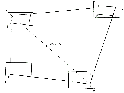
    Fig.1.12: Traversing Method

    Procedure:

  • Set up the instrument at station P. Select the point 'p' on the sheet. Center and level the table when the board is clamped.
  • Mark direction of magnetic meridian on sheet by trough or circular compass.
  • Touching the alidade on 'p' sight the ranging rod at Q and draw a ray.
  • Measure the distance PQ with chain or tap and lay it off to scale on the ray drawn towards Q. Thus, fixing the position of q on the sheet.
  • Shift the instrument and set up at Q, orient it by any method on P with the alidade along qp and then clamp the table.
  • With the alidade touching q, sight the station R and draw a ray.
  • Measure the distance QR and lay it off to scale on the ray drawn towards R to fix the point r on the sheet.
  • The nearby details are also located as usual.
  • Proceed the traverse until all the stations are plotted.
  • At any station the work can be checked by taking sights to two or more proceeding stations visible from the station occupied.
  • Uses:

    Traversing method is used:

  • For running survey lines between the stations previously fixed by any method.
  • To locate the topographical details.
  • For survey of roads, rivers etc.
  • 1.21.4 Resection Method:

  • Only the instrumentation stations established by this method.
  • After fixing the stations, details are located either by radiation or intersection.
  • Procedure:

  • As in the intersection method select a base line AB on the ground.
  • With the help of tape, measure it accurately and plot it to scale on the sheet as 'ab' in a suitable position.
  • Set up the table at A. Centre it so that A is exactly over A and then level it accurately.
  • Place the alidade along AB, then orient the table until ranging road at B is bisected and then clamp it.
  • With the alidade touching A, sight the station C which is to be located by resection and draw a ray along the ruling edge of the alidade. Mark the point 'c' along the rays by estimation.
  • Shift the table to point C such that 'e' is over C. Orient the table by back sight at point A and clamp it.
  • Place the alidade against b and sight B where the edge of alidade cuts (resects) draws a ray. The point of intersection of this ray and that preciously drawn from A gives the required point c.
  • Continue the process to establish the other station points.
  • The above explained method is also called as back ray method as it necessary to draw a ray from the preceding station to the station to be occupied by the plane table.
  • Errors in centering though inevitable, it will not affect the accuracy of the work as it is only used for small work.
  • Details are best located by radiation or intersection.
  • Key Takeaways:

    Methods of plane table surveying are as follows:

  • Radiation Method
  • Intersection method
  • Traversing method
  • Resection method
  •  


  • An art of measuring the relative heights or elevations of the points or objects on the surface of the earth is called as levelling.
  • Levelling deals with the measurements in a vertical plane.
  • It can also be defined as an operation for the measurements in a vertical plane.
  • 1.22.1 Types of leveling:

    Types of leveling are as follows:

    1. Simple leveling:

  • When the difference of leveling between two points is determined by setting the leveling instrument midway between the points, the process is called as simple leveling.
  • 2. Differential leveling:

  • It is adopted when-
  • The points are great distance apart
  • Difference of elevation between two point is large.
  • There is obstruction between the points
  • This method is also called as compound leveling. In this method the level is set up at several suitable position and staff reading are taken at all of these.
  • 3. Fly leveling:

  • When the differential leveling is done in order to connect a benchmark to the starting point of alignment of any project then it is called Fly levelling.
  • 4. Profile leveling:

  • The operation of taking level along the centerline of any alignment at regular interval is called as profile leveling.
  • 5. Cross-section leveling:

  • The operation taking transverse to the direction of longitudinal or profile leveling is known as cross section leveling.
  • Key Takeaways:

    There are five types of leveling:

  • Simple leveling
  • Differential leveling
  • Fly leveling
  • Profile leveling
  • Cross-section leveling
  •  


    Types of Benchmark area as follows:

    1. G.T.S. bench marks (Great trigonometrical survey bench marks):

  • These bench marks are established by the survey of India department throughout the country with very high precision with reference to mean sea level (m.s.l.) considered as zero level at Karachi in Pakistan.
  • The positions of G.T.S. bench marks and elevations are shown on the G.T.S. maps published by survey of India department.
  • Levelling work carried out with reference to G.T.S. bench marks give elevations of points with respect mean sea level.
  • 2. Permanent bench marks:

  • These are permanent reference points established with reference to G.T.S. benchmarks on permanent objects like bridge parapets, culverts, well, plinth of any government buildings.
  • The location and reduced level of this bench mark is usually marked on top of the permanent object.
  • 3. Arbitrary bench marks:

  • When small ordinary levelling work is to be carried out or when permanent bench marks are not nearby the place where survey is to be carried out, then to start the levelling work any prominent object like plinth or steps of the building etc. is chosen as bench mark and its elevation is assumed arbitrarily.
  • The elevation of points obtained in this type of levelling work are elevations with respect to the arbitrary bench mark and not with respect to mean sea level as the elevation of B.M. is assumed arbitrarily.
  • 4. Temporary bench marks:

  • The survey for big projects normally continues for a number of days. Hence at the end of the day, when the levelling work for that day has to be stopped, then any permanent object is chosen on which the work is stopped and can be started further on the next day. Then these types of bench marks chosen are known as temporary bench marks.
  • With reference to this temporary bench mark, the work is carried forward on the next day and so on.
  • Key Takeaways:

    There are four types of benchmarks:

  • G.T.S. bench marks (Great trigonometrical survey bench marks)
  • Permanent bench marks
  • Arbitrary bench marks
  • Temporary bench marks
  •  


  • The dumpy level is commonly used for levelling work being compact and stable type instrument. Fig. shows a dumpy level.
  • The purpose of dumpy level is to provide a horizontal line of sight after the adjustments are done.
  • The dumpy level consists of the following parts:
  • a)     A tripod stand

    b)    Levelling Head

    c)     Telescope

    (a) A tripod stand:

  • A tripod stand as shown in Fig. is used to support the dumpy level.
  • Before starting the levelling work, the dumpy level is mounted on the tripod and is fixed.
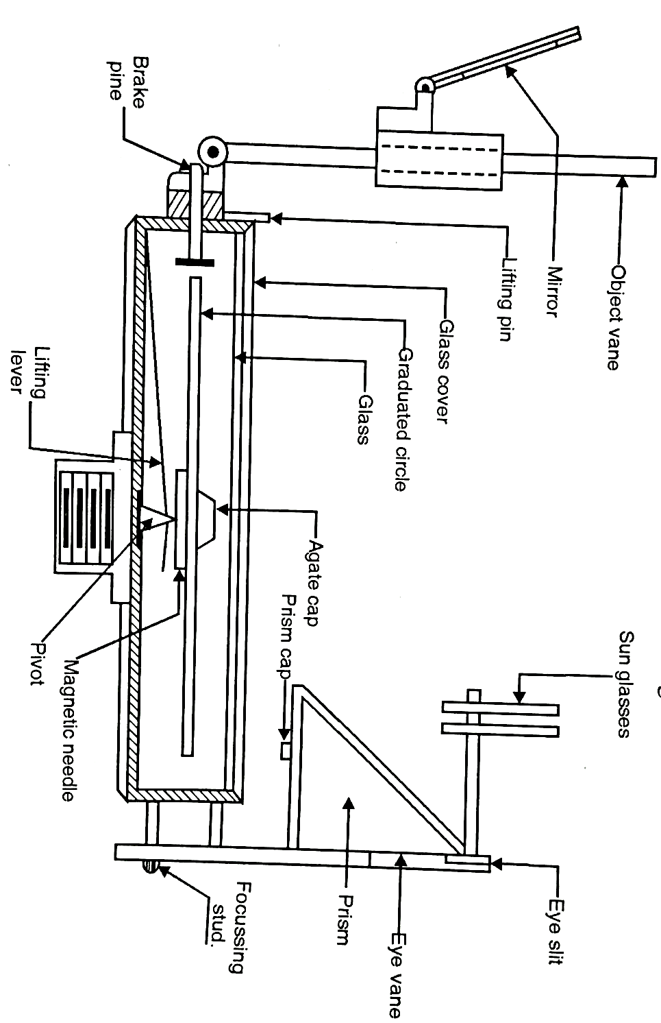
  • Fig.1.13: A tripod stand

    (b) Levelling head:

  • The levelling head levels the dumpy level instrument by bringing the bubble in its center of its run.
  • It consists of two parallel plates with minimum three-foot screws which bring the instrument in a proper level.
  • (c) Telescope:

  • In the dumpy level, a telescope is rigidly fixed to its supports and a bubble tube is placed parallel on top of telescope as shown in Fig.
  • The telescope consists of a movable eyepiece on one side and an object glass on the other side.
  • A diaphragm consisting of a circular glass with cross wires is fitted just in front of the eyepiece. Fig. shows a pattern of the diaphragm fitted just in front of eyepiece of dumpy level.
  • The eyepiece can be rotated either clockwise or anti-clockwise to make the cross wires of diaphragm clear and distinct.
  • A focusing screw is provided on the telescope to make the images of the object look clear and distinct and to bring the image in the plane of the cross-hairs of the the objective side to protect the object glass from diaphragm.
  • A ray shade is provided on the objective side to protect the object glass from direct rays of the sun.
  • Sometimes, a provision of a compass on the lower side of telescope is made for observing bearing of a line.
  • H:\unit 1 survey\IMG_20210525_193753.jpg

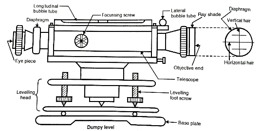
    Fig.1.14: Dumpy level

    Key Takeaways:

    The dumpy level is commonly used for levelling work being compact and stable type instrument


  • These instruments require only approximate levelling by reference to a good circular bubble, and they have no sensitive bubble.
  • The path of the line of sight through the telescope includes reflection at mirrors or prisms which are suspended on fine threads or on a component hanging as a pendulum and the mechanical design of the suspended portion is such that if the body of the instrument is slightly disturbed the consequent motion of the suspended component resets the line of sight into the former direction.
  • H:\unit 1 survey\IMG_20210525_193815.jpg

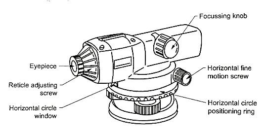
    Fig.1.15: Auto level

    Setting up the Instrument:

    H:\unit 1 survey\IMG_20210525_193836.jpg

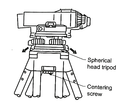
    Fig.1.16: Auto level

  • Spread the tripod legs about the same distance apart so that the tripod head is approximately level. Fix the tripod shoes firmly into the ground.
  • Hold the instrument on the tripod head and tighten the centering screw.
  • Level the instrument. When using the spherical head tripod, slightly loosen the centering screw, hold the base plate in both hands, one slide it across the tripod head until the bubble is in the proximity of the circular level.
  • Tighten the centering screw.
  • Adjust the levelling foot screws until the bubble is exactly centered in the center circle.
  • Focusing and Sighting:

  • Using the peep sight, aim the objective lens towards the staff.
  • Gradually turn the eyepiece until just before the reticle image becomes focused.
  • Turn the horizontal fine motion knobs until the staff is nearly centered in the field of view, then turn the focusing knob to focus on the staff.
  • Looking through the telescope, shift your eyes slightly up and down and to each side.
  • If the staff and reticle show no deviation, the instrument is ready for use. If the staff and reticle deviate, return to step 2.
  • If the reticle image is blurred, or deviation occurs at step 5, errors will occur when taking measurement results. Always make sure to adequately focus the staff.
  • Operation:

    Measuring height difference:
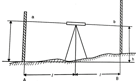
  • Set up the instrument at a point approximately halfway between points A and B.
  • For more accurate measurement, set the instrument as close to halfway as possible, to eliminate errors due to sighting axis misalignment.
  • Position the staff vertically at point A and take the reading a (backsight) on the staff at point A.
  • Then sight the staff at point B and obtain the reading b(foresight).
  • H:\unit 1 survey\IMG_20210525_193854.jpg

    Fig.1.17: Set up

  • The difference a - b is the height difference h of B from A. Example: h = a - b = 1.735 m- 1.244 m = 0.511 m
  • <When the distance between points A and B is large or if the height difference is great>
  • Divide the distance into a number of sections and determine the height difference of each section. The height difference between points A and B is the total of the height differences of all the sections using the following formula.
  • Altitude of the required point altitude of known point+ total of backsight values total of foresight values.
  • This simple leveling technique has no error check. It is better to measure from A to B and back to A so that the error of closure can be calculated.
  • Measuring Horizontal Angle:

  • The horizontal circle graduations are annotated in a clockwise direction. As a result, sighting is performed from left to right.
  • Set up the instrument directly above the surveying point.
  • Sight point A, and set the horizontal circle to 0° by turning the horizontal circle positioning ring.
  • Sight point B and take the angle reading.
  • Key Takeaways:

    These instruments require only approximate levelling by reference to a good circular bubble, and they have no sensitive bubble.


  • It is an automatic level consisting of pendulum compensator. It is capable for normal optical levelling with a rod graduated in meter or feet. Digital level has a provision to take readings automatically by using a bar code.
  • Digital level and bar code is as shown in Fig. It is an automatic level consisting of pendulum compensator. It is capable for normal optical levelling with a rod graduated in meter or feet. Digital level has a provision to take readings automatically by using a bar code.
  • Digital level and bar code is as shown in Fig.
  • It has digital and electronic image processing features which can be used to determine the heights and distances with the automatic recording of data which can further be transferred to computer database.
  • Length of the rod is 4.05 m and this rod is graduated in bar code on one side or on the both sides as shown in fig.
  • After capturing and processing the image of the bar code rod, this processed image of the rod reading is then compared with the image of the complete rod which is permanently stored in memory module of level so as to determine elevation i.e., height and distances.
  • Procedure:

  • First of all, the instrument is properly leveled.
  • The surveyor or observer focus the image of the bar code properly.
  • The observer or surveyor press the measure button to begin the image processing. This is normally done in 4 second.
  • The heights and distances are automatically measured along with horizontal angles.
  • In digital level, coding can be similar as used in total station which helps to collect processed levelling data which is further transferred directly to computer.
  • The range of bar code is 1.8 m to 100 m and the bar code can read within this range of 1.8 m to 100 m away from the instrument.
  • Note that of the rod is not held perfectly vertical or in plumb and then an error message I will automatically flash on the screen.
  • The messages line 'instrument not level', low battery and memory full are displayed on the screen.
  • Accuracy for distance can be obtained within the range of 1/2500 to 1/3000. Levelling accuracy is having standard deviation for a 1000 m double run of 2mm for optical measurement and that of for electronic measurement, it is 1.5 m.
  • Key Takeaways:

    It is an automatic level consisting of pendulum compensator. It is capable for normal optical levelling with a rod graduated in meter or feet. Digital level has a provision to take readings automatically by using a bar code


  • It is advanced type of instrument used in surveying work. It consists of a revolving laser beam to ensure precise horizontal level detection and dramatically improve the efficiency of levelling jobs on civil engineering and construction sites.
  • The main unit automatically emits a continuous laser beam that sweeps a full rotation of 360° so as to allow the operator to mark any location with loom radius.
  • Laser level is highly accurate instrument and very easy to use and operate and imparts the maximum efficiency while taking readings. With the help of laser level system, a single operator can perform even the most complicated levelling tasks.
  • The set up the main unit, just use the built-in circular spirit level to set the unit within 10' of horizontal. The automatic compensation mechanism makes sure the beam plane is perfectly level and ready for use. Its rugged, lightweight design and easy operation make it perfect for any kind of engineering, construction or interior application.
  • The beam detector gives the relative position of the beam with an easy-to-read display and audible tones for quick, precise marking.
  • Laser level instrument is waterproof and hence all the important components are protected from wet weather. Laser level imparts high precision, easy operation and proven durability in a single, compact package
  • Sokkia LP3A and Leica Javelin series lasers are the manufacturers of laser level. Sokkia LP3A level laser and Javelin laser level are available in market.
  • This type of laser instrument is used for fine grading, rough grading general construction work, excavation, land levelling steep slopes and land-fills.
  • Key Takeaways:

    Lazer level is advanced type of instrument used in surveying work. It consists of a revolving laser beam to ensure precise horizontal level detection and dramatically improve the efficiency of levelling jobs on civil engineering and construction sites


    Line of collimation:

  • It is the line joining the intersection of the cross-hairs of the diaphragm optical center of the object glass and its continuation further.
  • Line of collimation is also called the line of sight.
  • Axis of telescope:

  • It is the line joining the optical center of eyepiece and object glass.
  • H:\unit 1 survey\IMG_20210525_193950.jpg

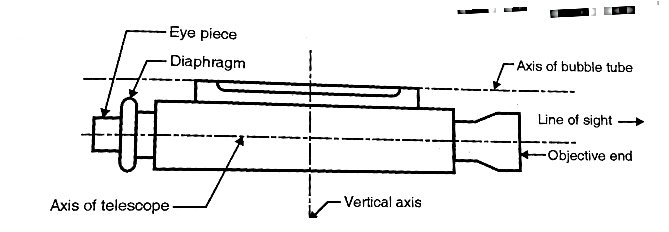
    Fig.1.18: Axes of Dumpy level

    Axis of the level tube:

  • It is an imaginary line which is tangential to the longitudinal curvature of the bubble tube at its center.
  • Axis of the level tube is also called the bubble tube axis.
  • Vertical axis:

  • It is the axis about which the telescope can be rotated in a horizontal plane.
  • Key Takeaways:

    There are four types of principle axis:

  • Line of collimation
  • Axis of telescope
  • Axis of level tube
  • Vertical axis
  •  


    There are following permenant adjustments:

  • Line of collimation parallel to axis of bubble tube
  • Line of collimation perpendicular to vertical axis.
  • Lne of collimation should be coinside with axis of telescope.
  •  


  • When it is necessary to carry levelling across a river or any obstacle a long sight between two points so situated that no place for the level can be found from which the lengths of foresight and backsight will be even approximately equal. Special method i.e., reciprocal levelling must be used to obtain accuracy and to eliminate the following errors due to
  • H:\unit 1 survey\IMG_20210525_194014.jpg

    Fig.1.19; Set up

  • Curvature and refraction
  • Error in instrument adjustment.
  • Reciprocal levelling involves:

  • Two sets of observations yielding two erroneous differences of level, the mean of which is the true result.
  • Thus, to ascertain the difference of level between P and Q, on the opposite banks of a wide river and remote from a bridge reading on a staff held on each point are taken from instrument station 1.
  • The instrument is then transferred to position 2, so that 2P is equal to 2Q.
  • The staff is again observed on P and Q.
  • If due to the combined effect of instrumental error, curvature and refraction on the long and short sights, the difference of level between P and Q, as determined from one of the instrument stations is made too great, the other determination evidently makes it too small by the same amount.
  • The mean of the two differences of level so obtained is therefore the required difference.
  •  


  • In precise levelling work or when the sights are long, the effects of curvature and refraction have to be taken into account.
  • It is evident that a horizontal line departs from a level surface because of the curvature of earth.
  • And in the long sights, the horizontal line of sight does not remain straight but it slightly bends downwards having concavity towards earth surface due to refraction.
  • The effect of curvature is to cause the objects sighted to appear lower than they really are.
  • While that of refraction is to make them appear higher than they really are.
  • The combined effect of curvature and refraction is such that objects appear lower than they really are.
  • Curvature:

  • The vertical distance between the horizontal line and the level line represents the effect of the curvature of the earth.
  • the correction for curvature in meter = 0.0785 d
  • where,

    d is the distance in km from the level to the staff station.

  • True staff reading may, therefore, be obtained by subtracting the correction for curvature from the observed staff reading
  • True staff reading = observed staff reading -0.0785 d²

    Refraction:

  • The effect of refraction is the same as if the line sight was curved downwards or concave towards the earth's surface and hence the rod reading is decreased.
  • The correction of refraction, C, is 0.01122d2 meters
  • where d is taken in km.

    Key Takeaways:

    In precise levelling work or when the sights are long, the effects of curvature and refraction have to be taken into account. It is evident that a horizontal line departs from a level surface because of the curvature of earth.


  • Let 'C' be the point of observation its height being equal to 'h'
  • Let 'A' be the point on the horizon i.e., a point where the tangent from P meets the level line.
  • If dv, is the distance to visible horizon it is given by dv,
    Km
  • d = 3.853 √C km.

    C being in meters. 


  • In this method, the reduced level of collimation plane or height of instrument is determined for each set up of dumpy level and then reduced levels (R.L.) of the other points are found out with respect to the plane of collimation or height of instrument.
  • Level page of the field book

    Staff Station

    B.S

    I.S

    F.S

    H.I

    (Collimation plane level)

    R.L

    Remarks

    B.M


    1


    2


    3


    Procedure:

  • Step 1: To prepare the format of level page before levelling work start:
  • For entering the readings of reduced level of different sights, the following format of level page is commonly used into practice.

  • Step 2: To find the height of instrument (H.I.) or R.L. of plane of collimation:
  • Keep the levelling staff on bench mark (B.M.) and take reading and find the reduced level of collimation plane or height of instrument by adding back sight reading to the R.L. of bench mark.

    Note that, Height of instrument is equal to R.L. of collimation plane.

    Height of instrument (H.I.) = R.L. of bench mark + B.S. reading.

  • Step 3: To find R.L. of intermediate points or change points:
  • Reduced level of intermediate points can be found out as follows:

    R.L. of intermediate points =Height of instrument - Intermediate sight reading

    =H.I-.I.S. reading

    R.L. of change point =Height of instrument - Fore sight reading

    = H.I. - F.S. reading

    Note: When levelling work is to be stopped or change point is to be taken, then foresight reading is taken.

  • Step 4: To find new height of instrument or new plane of collimation:
  • The instrument is shifted and set up and levelled at new position so that reading on levelling staff would be clear and distinct. Then take back sight reading on change point (C.P.) and find the R.L. of new collimation plane or new height of instrument. Refer to Fig.

    R.L. of new height of instrument =R.L. of change point + B.S.

    H:\unit 1 survey\IMG_20210525_194045.jpg

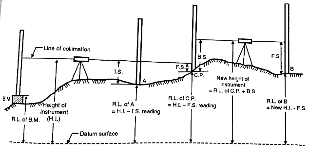
    Fig.1.20: H.I Reading method

  • Step 5: To find reduced levels of the remaining points:
  • Find the reduced levels of the remaining points from new set up of instrument with respect to new height of instrument or new R.L. of collimation plane.

  • Step 6: To finish the levelling work:
  • Repeat the above procedure till all the levelling work is over.

  • Step 7: To find arithmetical check:
  • After completion of levelling work, arithmetical check is found out. From this check. accuracy of the field work of levelling can be cross-checked. This check can be taken at each level page.

  • Arithmetical check:
  • Sum of backsights - sum of foresights =Last R.L. - First R.L.

    In short, . - .= Last R.L. - First R.L.

  • Note: It is noted that the arithmetical check can be taken at each level page.
  •  


  • In this method, instead of H.I. column in the format of level page, two columns of rise and fall are introduced for calculation of R. L’s. Difference of levels between consecutive points is found by comparing the staff readings on the two points for the same setting the instrument.
  • Rise and fall method is stepwise explained as follows:

  • Step 1: Prepare the format of level page before levelling work start, as shown below:
  • Level Page of field book

    Staff Station

    B. S

    I.S

    F. S

    Rise

    Fall

    R. L

    Remark

    B.M


    A


    B


    C


    .


    .


  • Step 2: The difference in staff readings between the consecutive points is found out.
  • Step 3:
  • If the staff reading of second point in level page is higher than the first, then it indicates fall which is then to be subtracted from R.L. of previous point.
  • If the staff reading of second point in level page is lower than the first one, then it indicates rise which is further to be added to the R.L. of previous point.
  • H:\unit 1 survey\IMG_20210525_194135.jpg

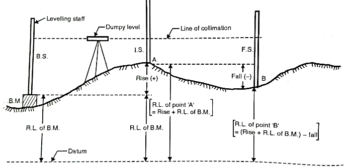
    Fig.1.21: Rise and fall method

  • Step 4: Repeat the same procedure till the levelling work is over.
  • Step 5: After completion of levelling work, the arithmetical check is found out, which shows accuracy and cross check of the field work in levelling. Note that, the check can be taken at each level page and on R.L., of every intermediate points.
  • Arithmetical check:
  • Sum of backsights - sum of foresights = Sum of all rise- sum of all= Last R.L. - First R.L.

    In short, Σ B.S. - . = Rise-fall=Last R.L – First R.L

  • Note: It is noted that arithmetical check can be taken on R.L. of intermediate points.
  • In this method calculation work is more, therefore it is tedious but there is check on every point; hence it is accurate method rather than H.I. method.
  • References:

  • Surveying and leveling by r. Subramanian, Oxford Publication
  • GPS Satellite Surveying-Alfred Leick-Wiley
  • Surveying and leveling Vol.1 and 2 by T.P. Kanetkar and S.V. Kulkarni Pune vidyarthi Griha Prakashan
  • Surveying by B.C. Punmia

  • Index
    Notes
    Highlighted
    Underlined
    :
    Browse by Topics
    :
    Notes
    Highlighted
    Underlined