Back to Study material
S

Unit - 2

Theodolite Surveying


  • The theodolite in which the telescope can be revolved through a complete revolution about its horizontal axis in a vertical plane is known as transit theodolite.
  • The theodolite is most accurate instrument used for measurement of horizontal and vertical angle.
  • It can also be used for various other purposes such as laying off horizontal angles, prolonging survey line, determining difference in elevation, locating points on a line, establishing grade etc.
  • Components of Transit Theodolite (20") and their Function:

    A transit theodolite essentially consists of following:

  • The levelling head
  • The two spindles
  • The lower circular metal plate
  • Vernier plate or upper plate
  • The telescope
  • The level tube
  • The standards
  • The vertical circle
  • The vernier frame
  • The compass
  • Clip screw
  • Optical plumet
  • Eyepiece
  • Shifting head
  • Bubble tube
  • Lower tangent screw
  • Key Takeaways:

    The theodolite in which the telescope can be revolved through a complete revolution about its horizontal axis in a vertical plane is known as transit theodolite.


  • Definition: The method in which the angle is measured in clockwise direction for any number of times is known as repetition method.
  • Usually six times, three repetitions with face left and three with face right.
  • One should note that, the accuracy will not increase by increasing the number of repetitions beyond a certain limit.
  • Procedure:

  • Set up the instrument over Q and level it accurately with the telescope in the normal position.
  • Set the vernier A to 360°. Loosen the lower clamp direct the telescope to left hand ranging rod at P, and bisect it exactly by using lower clamp and lower tangent.
  • The vernier readings should be the same.
  • Loose the upper clamp and turn the telescope in clockwise direction and bisect the right-hand ranging rod at R exactly by using the upper clamp and upper slow-motion screw.
  • Read both vernier. Let the mean reading be 30° 2' The object of reading both verniers is to obtain the approximate value of the angle,
  • Leaving the verniers unchanged unclamp the lower plate and turn the telescope in clockwise direction bisect the ranging rod at P exactly with lower clamp and lower tangent screw. The reading on vernier should be same as before.
  • Loose the upper clamp and turn the telescope in clockwise direction and bisect ranging rod at R exactly by using upper clamp and upper tangent screw
  • The verniers will now read twice the value of angle i.e., 2 x 30° 2'.
  • By leaving the verniers clamped at 60° 40' measure the angle third time.
  • Read both the verniers. Read the final angle.
  • The average angle with face left will be equal to the final reading divided by three.
  • Change the face and make three more repetition as described above.
  • Find the average angle with face right by dividing the final reading by three.
  • By taking average of both the face horizontal angle PQR is obtained.
  • Elimination or minimization of errors by method of repetition:

    Following errors can be eliminated or minimized by this method:

  • The errors due to eccentricity of verniers and centers are eliminated by taking vernier readings and averaging the readings.
  • The errors due to the imperfect adjustment of the line of collimation and the horizontal axis of the telescope are eliminated by face left and face right observation.
  • The errors due to in accurate graduations are minimized by taking the reading on different parts of the circle.
  • Key Takeaways:

    The method in which the angle is measured in clockwise direction for any number of times is known as repetition method.


  • Definition: A vertical angle is the angle between the inclined line of sight and the horizontal line.
  • If the angle is above the horizontal line, it is called as angle of elevation it is always considered as positive angle.
  • If the angle is below the horizontal line, it is called as angle of depression and it is always considered as negative angle.
  • Procedure:

    Fig.2.1: Measurement of vertical angle

  • To measure the vertical angle of an object P at a section O.
  • Set up the instrument over station O and level it carefully with respect to altitude bubble.
  • By means of vertical circle clamp and tangent screw, set zero of the vertical vernier exactly to the zero of the vertical circle.
  • Bring the bubble of the altitude level to the center of its run by means of the foot The line of collimation is thus made horizontal, while the vernier reads zero.
  • Loosen the vertical circle clamp and direct the telescope in vertical plane towards the object 'P' and bisect exactly using the vertical circle tangent screw.
  • Read both the verniers C and D. The mean of the two readings gives the values of the required angle for this face.
  • Change the face of the instrument and repeat the process. The mean of two vernier reading gives the values of the required for this face.
  • The average of two values obtained from left observation and face right observation gives exact values of the required angle.
  • Errors eliminated: The average of two values thus obtained gives required angle which is from instrumental error.
  • Key Takeaways:

    A vertical angle is the angle between the inclined line of sight and the horizontal line


  • Definition: A deflection angle is the angle which a survey line makes with the prolongation of the proceeding line.
  • Deflection angle vary from 0 to 180 degree but never more than 180°.
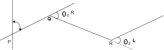
  • Fig.2.2: Deflection angle

  • Deflection angle measured in clockwise direction from the prolonged survey line is known as right deflection angle.
  • Deflection angle measured in anti-clockwise direction from the prolonged survey line is known as left deflection angle.
  • In the above figure
    , θ2 are deflection angles, survey line QR makes an angle θ1, with the prolongation of proceeding survey line PQ, similarly θ2, etc. are deflection angle.
  • Calculation:

    Deflection angle = 180°-included angle

    Procedure:

  • Set up the theodolite at Q and level it accurately
  • With both plates clamped, the vernier A reading 360° take back sight on p (i.e. bisect ranging rod at exactly)
  • Transit the telescope to direct the line of sight produced by PQ.
  • Loose the upper plate and turn to telescope clockwise to take fore sight on R (ie. bisect ranging rod at R exactly using upper clamp and its tangent screw). The mean of two vernier readings give the approximate value of deflection angle at Q.
  • Loose the lower clamp and turn the telescope horizontally to back sight on P. The verniers will read the same reading as in above step and the telescope inverted.
  • Transit the telescope Unclamp the plate and again bisect R read both verniers.
  • Find the mean of final vernier reading. Thus, the deflection angle is doubled and hence, one half of this average value gives the accurate value of deflection angle at Q.
  • Errors Eliminated:

    Following errors are eliminated by this process as the telescope is transited twice.

  • Errors of the eccentricity of the centers and verniers are eliminated as both verniers are read.
  • Eliminates errors caused by imperfect adjustments of instrument.
  • Key Takeaways:

    A deflection angle is the angle which a survey line makes with the prolongation of the proceeding line.


    Fig.2.3: Measurement of magnetic bearing

    Procedure:

  • Attach trough compass or circular box compass to the theodolite at the place provided.
  • Set up the instrument over station P and level it accurately.
  • Set the vernier A to 0° of the horizontal circle.
  • Unclamp the lower plate and release the magnetic needle. Rotate the instrument about its outer axis until the magnetic needle shows N and S directions exactly. The telescope is now pointing to the magnetic north, while the vernier, A reads zero.
  • Loosen the upper plate. Turn the telescope and bisect the station R exactly by using the upper clamp and its tangent screw.
  • Read both verniers. The mean of the two readings gives the magnetic bearings of the line PR.
  • Take both faces observation especially when a round of bearings is to be taken.
  •  


    There are three methods of prolonging a straight line by using theodolite.

    First method:

  • Set up the instrument over Q and level it accurately.
  • Back sight on the station P.
  • With both motions clamped, transit the telescope and set a point R in line beyond Q. Shift the instrument to R and bisect Q.
  • Transit the telescope and establish a point beyond R.
  • Continue the process until last point T is marked.
  • In this method there are chances of angular error if theodolite is not perfectly adjusted. Thus, false line of prolongation will be established.
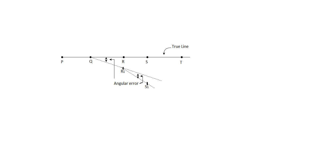
  • Fig.2.4: First method

    Second method:

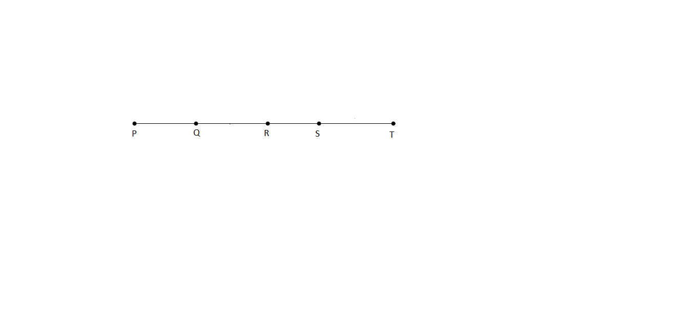
    Fig.2.5: Second method

    It is required to prolong a line PQ up to the point T.

  • Set up the instrument over P and level it accurately. Bisect Q exactly and establish a point R in the line beyond Q.
  • Move the instrument to point R and establish a point S in line beyond
  • Continue the process until the last point t is established.
  • Third method:

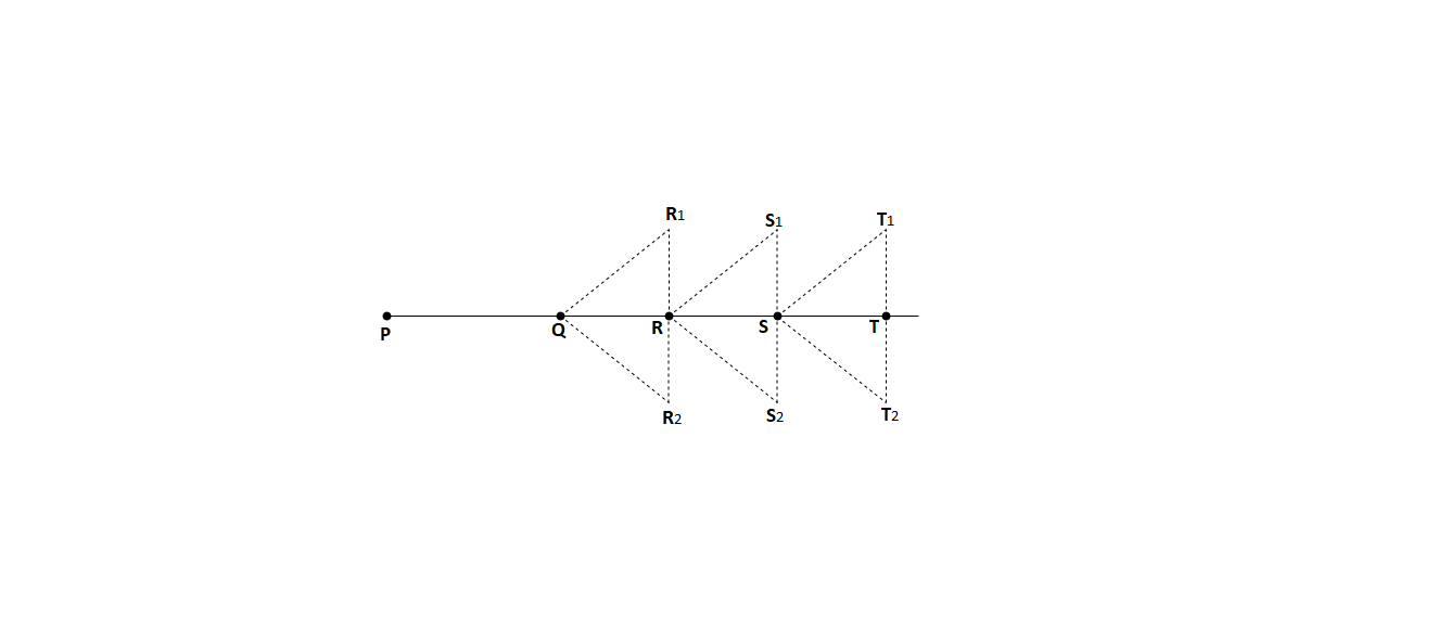
    Fig.2.6: Third method

  • This method is known as 'double sighting method' or 'double reversing method.
  • This method is used when the line is to be prolonged with a high precision or when the instrument is in poor adjustment.
  • Suppose if is required to prolong a line PR to some point T.
  • Procedure:

  • Set up the instrument over Q and level it accurately.
  • Bisect P exactly by using the lower clamp and tangent screw.
  • Transit the telescope and establish point R, on the line PQ produced.
  • Loosen the lower plate, revolve the telescope about its vertical axis and take back sight on P, using lower clamp and its tangent screw. Telescope position is now inverted.
  • Transit the telescope and establish a point R, in line PQ beside the point R, as shown in the Figure.
  • Measure R2R1 and establish R exactly midway which will be on the true prolongation of PQ.
  • Shift the theodolite to R double-sight on Q and establish the point S1S2.
  • Set the true point S exactly midway.
  • Repeat the process until the point T is established.
  • Key Takeaways:

    There are three types of methods:

  • First method
  • Second method
  • Third method
  •  


  • This is performed in 3 stages:
  • Centering the theodolites
  • Level-ling the theodolites
  • Removal of parallax.
  • This process could be encouraged wherein it's far assumed that the theodolite needs to be targeted over a nail withinside the pinnacle of a peg. It is a normal factor or reference mark used withinside the creation and placing out.
  • Tripod need to be saved head to degree while converting its role. When it's been targeted on this way, its legs are driven firmly into the ground. If one foot is going in extra than the others making its head burst off degree, this will be allowed for via way of means of loosening the clamp of the tripod leg affected, adjusting the period after which re-clamping. The theodolite is then taken out of its case, its genuine role is then cited to assist in replacement, and it's far securely connected to the tripod head. Whenever theodolite is to be carried, preserve it via way of means of the requirements and now no longer the telescope. Never allow cross of the theodolite till it's far firmly screwed onto the tripod.
  • The tripod is first installation over the peg. Its legs are located a same distance from the peg and are improved to in shape the peak of the observer. The tripod head need to be made as degree as viable via way of means of eye. Standing returned some paces from the tripod, the middle of the tripod head is checked to peer if it's far vertically above the peg – this ought to be finished via way of means of eye from instructions at proper angles.
  • Key Takeaways:

    This process could be encouraged wherein it's far assumed that the theodolite needs to be targeted over a nail withinside the pinnacle of a peg. It is a normal factor or reference mark used withinside the creation and placing out.


    The Fundamental Axes of the Theodolite are:

  • The vertical axis.
  • The axes of the plate levels.
  • The line of collimation (or the line of sight).
  • The horizontal axis (or trunnion axis or transverse axis).
  • The bubble line of the altitude (or azimuthal) level.
  •  


    Permanent adjustment of theodolite consists of the following:

  • Adjustment of plate levels.
  • Adjustment of the line of collimation.
  • Adjustment of the horizontal axis.
  • Adjustment of the level tube on the telescope.
  • Adjustment of the vertical index frame.
  • (1) Adjustment of plate level:

    Condition:

    To make the axis of plate level perpendicular to the vertical axis.

    Necessity:

  • If this condition is satisfied, the vertical axis will be truly vertical.
  • And horizontal circle and horizontal axis will both be truly horizontal, when the bubble is in center of its run.
  • Test:

  • Set up the theodolite on firm ground.
  • Level it accurately with bubble tube in two positions perpendicular to each other as in temporary adjustment.
  • Rotate the instrument about the vertical axis through 180°
  • If the bubble remains central, then the adjustment is correct.
  • Adjustment:

  • If not, note the deviation of the bubble, say n division
  • Bring each bubble halfway back i.e., n/2 by means of two capstan headed screws.
  • Repeat the test and adjustment until the bubble traverses in center during the whole revolution of the instrument.
  • (2) Adjustment of line of collimation:

    Condition:

  • To make the line of collimation right angle to the horizontal axis.
  • To satisfy the above condition adjustment is done in two steps.
  • Adjustment of the horizontal hair
  • Adjustment of the vertical hair
  • Necessity

    (a) Horizontal hair:

  • The object of this adjustment is to place the horizontal hair into the plane of motion of the optical center of the object glass.
  • Otherwise, the line of sight will change slightly during focusing of external focusing telescope.
  • This adjustment is necessary only when the instrument is used for measuring vertical angles or when it is used for leveling operations.
  • It is not important in measurement of horizontal angles.
  • (b) Vertical hair:

  • The adjustment of vertical hair is necessary when a line is to be prolonged either by transiting or changing the inclination of the telescope, or when a horizontal angle between two points at different levels is to be measured.
  • Testing and adjustment:

    (a) Horizontal hair:

    Test:

  • Select two station O and Q at a distance 100 m apart.
  • Select station P which is in line with OQ as shown in Fig. Set up the instrument at O and level it carefully.
  • With the telescope direct, take readings on the staff held on P and Q.
  • Transit the telescope and swing it through 180°.
  • Set the same reading on the vertical circle and sight the staff.
  • If the same reading is obtained in second position, the horizontal hair is in adjustment.
  • Adjustment:

  • If not, find the mean of two reading.
  • And adjust the diaphragm until the horizontal hair read the mean reading.
  • Repeat till perfect.
  • (b) Vertical hair:

    Test:

  • Set up the instrument at a convenient point on fairly level ground and level it accurately so that the length of about 100 m is available on either side of it.
  • Sight at a point m about 100 m away with telescope normal.
  • Now with both horizontal motions clamped, transit the telescope and mark a point N in the line of sight at about 100 m from instrument.
  • Unclamp the upper motion, swing through 180° and again sight at m. Clamp the upper motion and transit the telescope as before if n is on the line of sight, adjustment is correct.
  • Adjustment:

  • If not. set a point P on the line of sight beside n. Mark a point O such that PO = ¼ pn and adjust the cross hair until the line of sight, passes through O Repeat the procedure till there is no error.
  • (3) Adjustment of horizontal axis:

    Condition:

  • To make the horizontal axis perpendicular to the vertical axis.
  • Necessity:

  • By means of the second and third adjustments, we ensure that the line of sight will revolve in a vertical plane. The adjustment becomes essential in all work necessitating motions of the telescope in altitude.
  • Test:

  • Set up the instrument near high building or other object on which there is a defined point at a considerable altitude such as flag pole, lightening etc.
  • And mark a well-defined point A at a considerable height.
  • Level the instrument accurately, thus making vertical axis truly vertical.
  • Sight the point as shown in the Fig. and with horizontal motion clamped, depress the telescope and set a point P on or near the ground.
  • Unclamp and transit the telescope and swing through 180° with the telescope inverted, again sight on P.
  • Depress the telescope as before, if the line of sight falls on P. the horizontal axis is perpendicular to the vertical axis.
  • Adjustment:

  • If not, mark another point Q in the line of sight on the wall at the same level
  • Mark point R midway between P and Q sight on the point R.
  • Clamp the upper motion.
  • Raise the telescope.
  • The line of sight will now strike the point A.
  • Raise or lower the adjustable end of the horizontal axis by means of screws near the top of the standard until the line of sight passes through the point S. This method is known as the spine test.
  • (4) Adjustment of the bubble line of the altitude level:

    Condition:

  • To make the axis of the telescope level parallel to the line of collimation.
  • Necessity:

  • Due to this, the line of collimation become horizontal when the telescope bubble is brought in the centre. The adjustment is a necessity when the theodolite is to be used as a level or when vertical angles are to be measured.
  • Test:

  • Derive two pegs P and Q on a level ground. Some distance apart says 100 m.
  • Set up the theodolite at O exactly midway between P and Q.
  • Clamp the vertical circle and bring the telescope bubble to the centre of its by means of the tangent screw of the vertical circle.
  • With the bubble exactly central, take readings on the staff held on P and Q find the difference between the readings which gives true difference between P and Q.
  • Shift the instrument and set it up at O1 on the line QP produced at about 10 from P. Level it accurately.
  • With the bubble exactly centred, read the staff on P and then on Q and find the difference between the two readings.
  • If this difference agrees with the first different, the adjustment is correct.
  • Adjustment:

  • If not, calculate the correct staff reading P and Q.
  • Bring the horizontal hair exactly to the correct Q by means of the tangent screw of the vertical circle.
  • Bring the bubble exactly to the centre of its run by means of the level tube nuts.
  • Sight the staff on the near peg and note calculated correct reading is obtained.
  • Repeat the process until the test is satisfied.
  • (5) Adjustment of the vertical index frame:

    Condition:

  • To make the vertical circle read zero when the line of collimation is horizontal.
  • Necessity:

  • If this is not achieved, the vertical circle will not read zero, when the bubble is centered and the line of sight is horizontal. The reading on the vernier, when the line of sight is horizontal, is known as index error, which will be added or subtracted from the observed value if the adjustment is not done.
  • Test:

  • Having centred the plate bubbles, bring the telescope bubble to the center of its run by means of vertical tangent screw as in first adjustment and red the vernier of the vertical circle.
  • Adjustment:

  • If the vernier does not read zero, loosen it and move it until it read zero by means of the screws which hold it to the standard.
  • If the vernier is not adjustable, note the angular error.
  • This angular error is called "index error and is applied as a correction to the observed values of vertical angles
  • Key Takeaways:

    Permanent adjustment of theodolite consists of the following:

  • Adjustment of plate levels.
  • Adjustment of the line of collimation.
  • Adjustment of the horizontal axis.
  • Adjustment of the level tube on the telescope.
  • Adjustment of the vertical index frame.
  •  


  • The technique of repetition used to degree traverse angles to a finer diploma of accuracy than that workable with the least be counted number of the vernier geared up at the theodolite.
  • In this technique, an attitude degree there or 4 instances through maintaining the vernier clamp while sighting on the lower back station.
  • While swinging from forwarding station to lower back station, the top plate is set free and made unfastened to rotate.
  • Thus, an attitude analyzing routinely provides as commonly because the wide variety of repetitions. The distinction among the primary and the ultimate analyzing 5 the incorporated traverse attitude and the common traverse attitude then acquired through dividing the incorporated attitude through the wide variety of repetitions.
  • Key Takeaways:

    The technique of repetition used to degree traverse angles to a finer diploma of accuracy than that workable with the least be counted number of the vernier geared up at the theodolite.


  • The traverse stations are plotted on a map with reference to the axes of co-ordinates OY and OX which are parallel and perpendicular to the meridian.
  • These reference lines are known as the axis of co-ordinates and the point of their intersection O as the origin.
  • The co-ordinates of each point are the distances of that point from each of the co ordinate axes. The projections of the survey line parallel to the meridian is called Latitude.
  • Latitude of line is the distance measured parallel to N-S line. Latitude is positive when measured northward or upward it is called as Northing. Latitude (L) is negative when measured southward or downward. It is called as Southing.
  • Latitude of a line = lcos
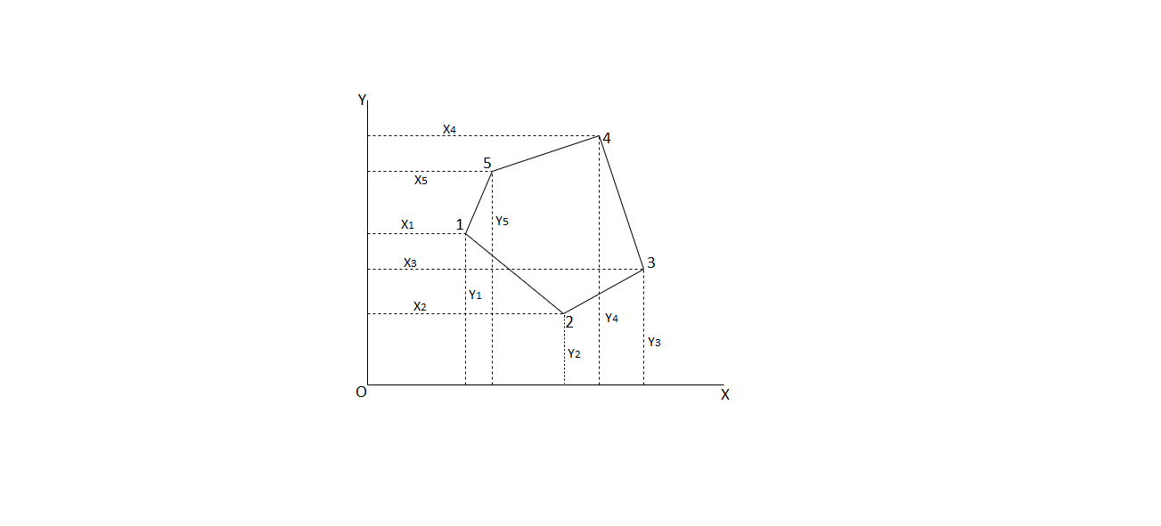
  • Fig.2.7: Traverse computation

  • The projection of the survey line perpendicular to the meridian is called departure.
  • Departure of a line is the distance measured parallel to the line EW and perpendicular to N-S line.
  • Departure is positive when measured eastward or to the right it is called as Easting.
  • Departure is negative when measured westward or to the left it is called as Westing.
  • Departure of a line = l sin
  • = the reduced bearing of the line,

    l= the length of line.

    Consecutive Co-ordinates:

  • The latitude and departure of any point with reference to the preceeding point are called consecutive co-ordinates of the point.
  • Independent Co-ordinates: (Total Latitude and Total Departure)

  • The co-ordinates of any point with respect to a common origin are called as independent co-ordinates of the point.
  • Key Takeaways:

    Consecutive Co-ordinates: The latitude and departure of any point with reference to the preceeding point are called consecutive co-ordinates of the point.

    Independent Co-ordinates: The co-ordinates of any point with respect to a common origin are called as independent co-ordinates of the point.


    The transit rule may be employed to balance the traverse when the angular measurements are more precise than the linear measurement.

    Correction to latitude of any side= Total error in latitude×

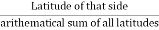
    Correction to departure of any side=

    Total error in departure x


  • This rule, also termed as the compass rule.
  • It is used to balance the traverse when the angular and linear measurements are equally precise.
  • By this rule, the total error in latitude and in departure is distributed in to the lengths of the sides.
  • It is the rule most commonly used in traverse adjustment.
  • Correction to latitude or departure of any side=
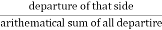
  • Total error in latitude or departure×


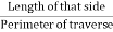
    The calculations for a closed traverse may be made in the following steps and entered in a tabular form which is known as Gale's Traverse Table:

  • Sum up all the included angles. Their sum should be equal to (2N ± 4) right angles according as the interior and exterior angles are measured, where N is the number of the sides of a traverse.
  • If not, apply the necessary corrections to the angles so that the sum of the corrected angles will exactly equal (2N ± 4) 90°.
  • Calculate the whole circle bearing of the other lines from observed bearing of the first line and then corrected included angles.
  • From the whole circle of the lines deduce the reduced bearings of the lines, and determine the quadrants in which the lines lie.
  • From the given lengths and the calculated reduced bearings of the lines, compute their latitudes and departures i.e., consecutive co-ordinates.
  • Add all, northing and southings, find the differences between the two sums. Similarly, obtain the difference between the sum of all eastings and the sum of all westing.
  • Apply necessary corrections by using Bowditch's rule or transit rule so the sum of northing sum of southings and sum of easting sum of westings.
  • From the corrected consecutive co-ordinates calculate the independent co-ordinates of the points so that they are all positive. Then the whole traverse will lie in the first quadrant.
  •  


  • There are a few not unusual place styles of not noted dimension in closed traverse this is as follow:
  • Length of 1 line is not noted.
  • Length of traces aren't measured.
  • Length of 1 line and bearing of different line aren't measured.
  • Bearing of 1 line is missing.
  • Bearing and duration of equal line are missing.
  • Bearing of traces are missing.
  • This instance is generally visible whilst there may be a few barriers like river is among taking analyzing in subject in theodolite surveying.  However, through the usage of the above components and a few calculations, we will locate all statistics associated not noted readings.
  • There are a few strategies for every case and through these strategies we get the all not noted measurements. These strategies are in info given underneath with every case and the method for every element to understand not noted readings withinside the traversing.
  •  


  • The given consecutive coordinates of a traverse are converted into independent co-ordinates with reference to the co-ordinates of the most westernly, thus the whole traverse is transferred to the 1st quadrant.
  • In Fig. A is the most westernly station then the coordinates are arranged in determinant form as follows-
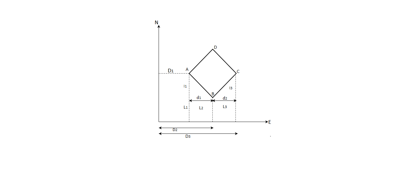
  • Fig.2.8: Area calculation

  • The sum of the products of coordinates joined by solid line,
  • = (y1x2+y2x3+y3x4+y4x5+y5x1)

  • The sum of the products of the co-ordinates joined by the dotted line,
  • = (x1y2+x2y3+x3y4+x4y5+x5y1)

  • The difference between above two sum gives the double area of traverse.
  • Double area=-

    Required area= -)

    Key Takeaways:

    The given consecutive coordinates of a traverse are converted into independent co-ordinates with reference to the co-ordinates of the most westernly, thus the whole traverse is transferred to the 1st quadrant.

    References:

  • Surveying and leveling by r. Subramanian, Oxford Publication
  • GPS Satellite Surveying-Alfred Leick-Wiley
  • Surveying and leveling Vol.1 and 2 by T.P. Kanetkar and S.V. Kulkarni Pune vidyarthi Griha Prakashan
  • Surveying by B.C. Punmia
  •  


    Index
    Notes
    Highlighted
    Underlined
    :
    Browse by Topics
    :
    Notes
    Highlighted
    Underlined