Unit - 1
Flow Over Notches and Weirs
A notch is an opening in the vertical side of a tank such that the liquid in the tank is below the edge of the opening.
It is used to measure discharge through an open channel.
Classification of notches
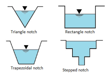
- Depending upon shapes
- Rectangular notch
- Triangular notches or V- notch
- Trapezoidal notches
- Stepped notches
B. Based on the effect of slides
- Notch with end contraction
- Notch without end contraction or suppressed notch
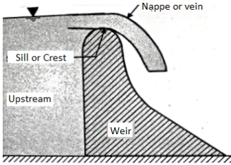
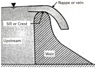
A weir is concrete or masonary dam built across an open channel (i.e. river, canal etc) over which overflow
It is used to overflow the excess flood water entering a reservoir
When the water overflows over the dam, the weir behaves exactly like a notch
Classification of weirs
- According to shape
- Rectangular weir
- Triangular weir
- Trapezoidal weir
- Cippoletti weir
- Stepped channel
B. According to nature of discharge
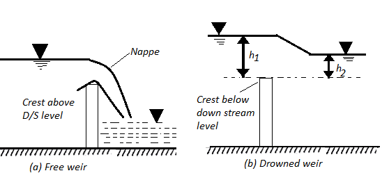
- Ordinary of free weir
- Submerged or drowned weir
C. According to the width of crest
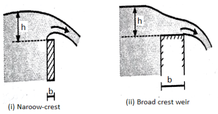
- Narrow crested weir (b<0.5 h)
- Broad crested weir (b>0.5 h)
D. According to nature of crest
- Sharp crested weir
- Ogee weir
Key takeaways:
- Depending upon shapes
- Rectangular notch
- Triangular notches or V- notch
- Trapezoidal notches
- Stepped notches
2. Based on the effect of slides
- Notch with end contraction
- Notch without end contraction or suppressed notch
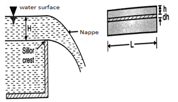
Consider a rectangular channel provided in a channel carrying water
Let H== head of water over crest
L= length of the notch
Cd = coefficient of discharge
Now consider a horizontal strip of water thickness dh at a depth h from free surface as shown in fig.

Theoretical velocity

Discharge through the strip


The total discharge over the notch is obtained by integrating equation

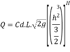

The Francis (1883) equation is handy for weirs working beneath favorable prescribed conditions. The Francis equation is:

Rectangular weirs are used to extract water so that you can emulate the impact of off take discharges in actual irrigation canals. It is feasible to reap the waft fee extracted with the aid of using measuring the water degree upstream of the weir
In a suppressed square weir, the nappe stretches from channel wall to channel wall. On the downstream facet of the weir, the air beneath the nappe becomes entrained within side the nappe because it passes over it because it spills into the downstream channel.
As the air turns into entrained, there may be much less and much less air beneath the nappe. This discount of air beneath the nappe creates a strain gradient. Ultimately the nappe collapses in opposition to the downstream face of the weir until new air is permitted to top off the entrained air.
Aeration and Weir Accuracy: Insufficient aeration, whether or not with the aid of using negative sidewall geometry or inadequate vertical drop from the weir crest to the downstream water floor can boom discharge with the aid of using as tons as 25%, ensuing in float readings which can be dramatically exceptional than could in any other case be received with the aid of using an aerated weir nappe.
Keeping the Nappe Aerated: To keep away from the nappe collapses in opposition to the face of the weir, air need to be allowed to top off that that's entrained with the aid of using the nappe The simplest manner to do that is to region vents on each aspects of the weir beneath the nappe.
Key takeaways:
- Rectangular weirs are used to extract water so that you can emulate the impact of off take discharges in actual irrigation canals.
- It is feasible to reap the waft fee extracted with the aid of using measuring the water degree upstream of the weir
- In a suppressed square weir, the nappe stretches from channel wall to channel wall.
- On the downstream facet of the weir, the air beneath the nappe becomes entrained within side the nappe because it passes over it because it spills into the downstream channel.
A triangular notch is also called as V notch
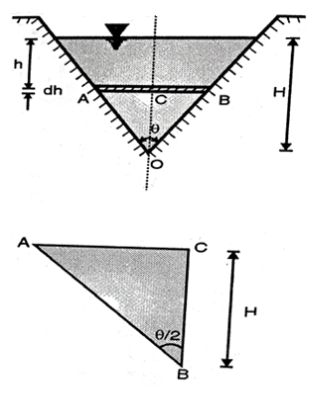
Consider a triangular notch on the one side of tank
Let
H = height of water above the notch
 = Angle of notch
Cd = coefficient of discharge
Now, consider a horizontal strip of water of thickness dh at a depth of h from free surface
From triangle


Width of strip AB = 2 AC = 2
Area of strip = ABdh = 
We know that the theoretical velocity of water through the strip= 
Discharge through the strip


From total discharge integrate the above Equation


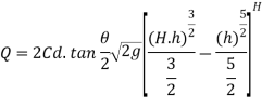


If V notch is right angle  = 90degree and Cd= 0.6
 = 1 put in above equation


A trapezoidal notch is combination of trianagular notch and rectangular notch
Let
H = Height of water over the notch
L= Length of rectangular portion of the notch
Cd = coefficient of discharge
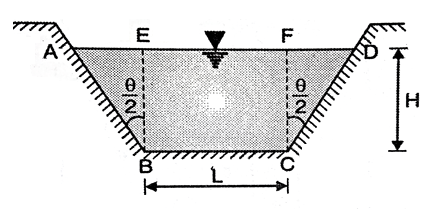
Discharge through central of rectangular portion

Discharge through central of triangular portion

Discharge through trapezoidal portion


It is a trapezoidal weir which has side slope of 1 horizontal to 4 vertical
It has an advantages over a rectangular weir that is decrease in discharge due to end contraction is balanced by the discharge throughthe triangular portion
Discharge through cipolleti weir is calculated by using formu;a of discharge rectangular wire by using 
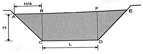
Discharge through rectangular weir dur to end contraction is


The discharge due to end contraction is decrease by

This decrease in discharge is balance by discharge through triangular portion which is obtained by giving side slope
Discharge through triangular weir of vertex angle 

Equating equation above


Discharge through cipolleti weir = Discharge through rectangular portion of weir

- Narrow crested weir
When the width of the weir is less than half of the height of water above the crest the weir is known as narrow crest weir
b < 0.5 H
Discharge through narrow crested weir


L = length of weir
H = Height of water above the crest
2. Ogee weir
Ogee weir used as a spillway for the concrete dams
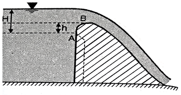
The water level near the crest a point a rise slight and reaches maximum at point B and then falls down parabolic ally down
h= 0.511 H
Discharge over the ogee weir is given by the same equation used for sharp crested weir

3. Submerged weir
When the water level on the down stream side of the weir is rise above the level of the crest the weir is said to be submerged weir
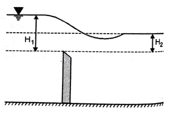
H1 is the height of water level at upstream and H2 is the height of water level on downstream side
The discharge Q over the upper portion as free discharge under the head of (H1-H2)
Q1 is the discharge over the upper portion as free discharge under the head of (H1-H2)

Q2 is the discharge over the lower portion which is submerged under head H2

Total discharge

A Notch is a tool used for measuring the charge of float of a liquid thru a small channel or a tank. It can be described as a gap within side the aspect of a tank or vessel inclusive of liquid floor within side the tank is underneath the extent of opening. Notches may be of various shapes inclusive of triangular, rectangular, trapezoidal, stepped notch, etc. the lowest of the notch over which the water flows is referred to as crest or sill and the skinny sheet of water flowing thru the notch is referred to as nappe or vein. The edges of the notch are bevelled at the downstream aspect a good way to have a sharp-edged aspects and crest ensuing in minimal touch with the flowing fluid.
A broad-crested weir is an overflow shape with a horizontal crest above which the deviation from a hydrostatic stress distribution due to centripetal acceleration can be neglected. In different words, the streamlines are nearly straight and parallel. To reap this example the duration of the weir crest within side the direction of flow (L) must be associated with the overall electricity head over the weir crest as u7 < H> 0.50, so that only light curvature-l G s occur T above the crest and a hydrostatic stress distribution can be assumed. If the measuring shape is so designed that there aren't anyt any tremendous electricity losses within side the sector of acceleration upstream of the manage section
Key takeaways:
- A Notch is a tool used for measuring the charge of float of a liquid thru a small channel or a tank.
- It can be described as a gap within side the aspect of a tank or vessel inclusive of liquid floor within side the tank is underneath the extent of opening.
- Notches may be of various shapes inclusive of triangular, rectangular, trapezoidal, stepped notch, etc
Whenever an obstruction is occurred in the path of flow the depth of flow at first less than the critical depth yc and then the depth of water increase rapid ally over a short length towards the downstream as shown in fig
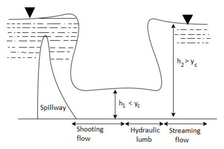
Thus there is a sudden change of flow from super critical flow to sub critical flow. The increase in depth occurs in a short length in channel is known as hydraulic jump or standing wave. The flow at the jump is steady but non uniform
The jump converts the kinetic energy of the rapidly flowing stream into potential energy
During the jump in a flow there is a loss of kinetic energy
Hydraulic jump is utilized in dissipating the surplus energy of water flowing through an open channel. After the jump water flows with a greater height and small velocity The dissipation of energy during hydraulic jump is a desirable phenomena as it prevent the scoring of the bottom of the back side of the dam.
A hydraulic jumps occurs in the following situation:
- On the downstream of sluice gate
- At the foot of spillways
- When the gradient is suddenly change from a steep slope to a flat slope
- When a rapid flow meets a streaming flow having a larger depth
Advantages:
- It helps in dissipating excess energy of water flowing over the spillway of hydraulic dams
- When y2>y1 in case of hydraulic jump it helps for better irrigation.
- It helps to increase the weight on an apron of hydraulic structure due to increase in depth of flow and hence the uplift pressure acting an apron is considerably counterbalanced
- It is used to remove air pockets from water supply pipes
- It is used for aeration and dechlorination of waste water
Assumptions:
- The slope of channel is very small hence the corresponding weight component in the direction of flow is negligible.
- No friction at the sides and channel bed
- The flow is uniform
- Pressure distribution is hydrostatic before and after the jump
- Hydraulic jump occurs abruptly.
Key takeaways:
- Thus there is a sudden change of flow from super critical flow to sub critical flow.
- The increase in depth occurs in a short length in channel is known as hydraulic jump or standing wave.
- The flow at the jump is steady but non uniform
Consider two section 1-1 on the upstream and 2-2 on the downstream of the hydraulic jump
Let y1 and y2 are depth of flow at section 1-1 and 2-2
V1 and v2 are velocity at section
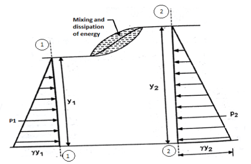
1-1 and at section 2-2
A1 and A2 are area of flow at section 1-1 and at a section 2-2
Discharge per unit width of channel q= Q/b

Pressure force at section 1-1= Area of pressure diagram at section 1-1 = 
Pressure force at section 2-2= Area of pressure diagram at section 2-2 = 
Net force acting on the mass of water between section 1-1 and 2-2


Where  = Specific weight of water but net force must be equals to rate of change of momentum
Net force = (mass of water/sec) x change in velocity

From equating above equation


But v1 = q/y1 and v2 = q/y2 put in equation


Multiplying both side by y2 we get

Solving equation by quadratic equation


If the upstream depth y1 and velocity v1 are known the downstream depth y2 can be found out from equation then hydraulic jump = y2-y1
Conjugate depth:
The two depth y1 and y2 between which specific energy E1 and E2 is conserved this depth is called an alternate depth. Alternate depth valid over energy conserving devices e.g sluice gate
When the hydraulic jump occurs some energy of flowing water is lost due to formation of eddy current and turbulent flow
Let
E1 = specific energy occurs at section 1-1
E2 = specific energy at section 2-2
Loss of energy


Substitute


Substituting value of q^2 we get,


Hydraulic jump based on Froude’s number are classified into five categories
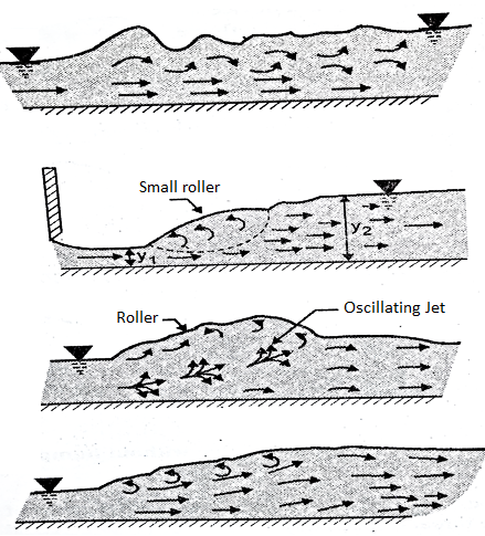
- Undular jump
- Weak jump
- Oscillating jump
- Steady jump
- Strong jump
- Undular jump
Froude number lies between 1 to1.7
The water surface is undulating with a very slight ripple on the surface
Energy loss is practically zero
2. Weak jump
Froude number lies between 1.7 to 2.5 . Small rollers are developed on the water surface
Water surface is smooth after the jump
Energy loss is very small is about 5 to 18%
3. Oscilating jump
Froude number lies between 2.5 to 4.5
Formation of large waves of irregular periods
Waves are transmitted downstream which cause damage to embankment
4. Steady jump
Froude number lies between 4.5 to 9
A clear distinct steady hydraulic jump is formed
The energy loss range from 40 to 70%
5. Strong jump
Froude number is greater than 9
The water surface is very rough and chopy and continues for long distance on downstream
Energy dissipation can be upto 70%
Key takeaways:
- Froude number lies between 1 to1.7
- The water surface is undulating with a very slight ripple on the surface
Energy loss is practically zero
Case Study
- Hydraulic Jump
Thus there is a sudden change of flow from super critical flow to sub critical flow. The increase in depth occurs in a short length in channel is known as hydraulic jump or standing wave. The flow at the jump is steady but non uniform
The jump converts the kinetic energy of the rapidly flowing stream into potential energy
During the jump in a flow there is a loss of kinetic energy
Hydraulic jump is utilized in dissipating the surplus energy of water flowing through an open channel. After the jump water flows with a greater height and small velocity The dissipation of energy during hydraulic jump is a desirable phenomena as it prevent the scoring of the bottom of the back side of the dam.
A hydraulic jumps occurs in the following situation:
5. On the downstream of sluice gate
6. At the foot of spillways
7. When the gradient is suddenly change from a steep slope to a flat slope
8. When a rapid flow meets a streaming flow having a larger depth
Advantages:
6. It helps in dissipating excess energy of water flowing over the spillway of hydraulic dams
7. When y2>y1 in case of hydraulic jump it helps for better irrigation.
8. It helps to increase the weight on an apron of hydraulic structure due to increase in depth of flow and hence the uplift pressure acting an apron is considerably counterbalanced
9. It is used to remove air pockets from water supply pipes
10. It is used for aeration and dechlorination of waste water
Assumptions:
6. The slope of channel is very small hence the corresponding weight component in the direction of flow is negligible.
7. No friction at the sides and channel bed
8. The flow is uniform
9. Pressure distribution is hydrostatic before and after the jump
Hydraulic jump occurs abruptly.
2. Weir and Notches:
Rectangular weirs are used to extract water so that you can emulate the impact of off take discharges in actual irrigation canals. It is feasible to reap the waft fee extracted with the aid of using measuring the water degree upstream of the weir
In a suppressed square weir, the nappe stretches from channel wall to channel wall. On the downstream facet of the weir, the air beneath the nappe becomes entrained within side the nappe because it passes over it because it spills into the downstream channel.
As the air turns into entrained, there may be much less and much less air beneath the nappe. This discount of air beneath the nappe creates a strain gradient. Ultimately the nappe collapses in opposition to the downstream face of the weir until new air is permitted to top off the entrained air.
Aeration and Weir Accuracy: Insufficient aeration, whether or not with the aid of using negative sidewall geometry or inadequate vertical drop from the weir crest to the downstream water floor can boom discharge with the aid of using as tons as 25%, ensuing in float readings which can be dramatically exceptional than could in any other case be received with the aid of using an aerated weir nappe.
Keeping the Nappe Aerated: To keep away from the nappe collapses in opposition to the face of the weir, air need to be allowed to top off that that's entrained with the aid of using the nappe The simplest manner to do that is to region vents on each aspects of the weir beneath the nappe.
A notch is an opening in the vertical side of a tank such that the liquid in the tank is below the edge of the opening.
It is used to measure discharge through an open channel.
Classification of notches
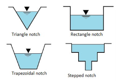
- Depending upon shapes
Rectangular notch
Triangular notches or V- notch
Trapezoidal notches
Stepped notches
B. Based on the effect of slides
Notch with end contraction
Notch without end contraction or suppressed notch
A weir is concrete or masonary dam built across an open channel (i.e. river, canal etc) over which overflow
It is used to overflow the excess flood water entering a reservoir
When the water overflows over the dam, the weir behaves exactly like a notch
Classification of weirs
- According to shape
- Rectangular weir
- Triangular weir
- Trapezoidal weir
- Cippoletti weir
- Stepped channel
B. According to nature of discharge
- Ordinary of free weir
- Submerged or drowned weir
C. According to the width of crest
- Narrow crested weir (b<0.5 h)
- Broad crested weir (b>0.5 h)
D. According to nature of crest
- Sharp crested weir
- Ogee weir
References:
- Engineering Fluid Mechanics, Garde and Mirajgaonkar, Scitech
- A Text Book on Fluid Mechanics and Hydraulic Machines, Sukumar Pati, McGraw Hill, New Delhi
- A Text Book of Fluid Mechanics and Hydraulic Machines, R K Bansal, Laxmi
Publications Pvt. Ltd., New Delhi
4. Fluid Mechanics, Fundamentals and Applications, Yunus A Cengel and John Cimbala, McGraw Hill International, New Delhi
5. Fluid Mechanics by Frank M White, McGraw Hill
6. Fluid Mechanics by Streeter, Wylie and Bedford, McGraw Hill International, New Delhi