Unit - 6
Centrifugal Pumps
A centrifugal pump has the following main components as:
1. Impeller
2. Suction pipe with strainer and foot valve
2. Casing
4. Delivery pipe
- Impeller
An impeller is a wheel or rotor having a series of backward curved vanes or blades.
The impeller is mounted on a shaft which is usually coupled to a motor. The motor provides the required energy to rotate the impeller.
2. Casing
The impeller is enclosed in a watertight casing with delivery pipe on one side and with an arrangement on suction side called eve of impeller as shown in Fig.
Casing has to perform two functions. Firstly, it guides the water from entry to exit of impeller Secondly, the casing is so designed that it helps in partly converting the kinetic energy of the liquid into pressure energy.
3. Suction pipe with strainer and foot valve
The pipe which connects the sump to the eye of impeller is called suction pipe. The sump carries the liquid to be lifted by the pump.
The suction pipe at its inlet is provided with a strainer and a foot valve. The function of strainer is to prevent the entry of any debris into the pump. The foot valve is a non-return valve which allows the flow of water only in upward direction.
Therefore, this valve does not allow the liquid to drain out from suction pipe.
4. Delivery pipe
The pipe which connects the outlet of pump up to point it delivers the liquid to require height is called delivery pipe. A valve is provided in the delivery pipe near the outlet of the pump called delivery valve. It is a sluice open. Its function is to regulate the supply of liquid from the pump to delivery pipe.
5. Casing
The impeller is enclosed in a watertight casing with delivery pipe on one side
Key takeaways:
- An impeller is a wheel or rotor having a series of backward curved vanes or blades.
- The impeller is mounted on a shaft which is usually coupled to a motor.
- The motor provides the required energy to rotate the impeller
Working of Centrifugal Pump:
Centrifugal pump works on the principle that when a certain mass of liquid is made to rotate along the impeller from the central axis of rotation, it impresses a centrifugal heat. It causes the water to move racially outwards at higher velocity and causes the water to rise to a higher level. The motion of water is restricted by casing of pump, it results into pressure build up. In addition, the change in angular momentum of liquid during its flow results into increase in pressure head.
The steps involved in operation of centrifugal pump are as follows:
1. The delivery valve is closed.
2. The priming of the pump is carried out Priming involves the filling the liquid in suction pipe and casing up to the level of delivery valve so that no air pockets are left in the system If any air or gas pockets are left in this portion of pump, it may result into no delivery of liquid by the pump.
3. The pump shaft and impeller is now rotated with the help of an external source of power like a motor or any other prime mover,
4. The rotation of impeller inside a casing full of liquid produces a forced vortex which is responsible in imparting the centrifugal head to the lignite creates a vacuum at the eye of impeller and causes liquid to raise into suction pipe from the sump
4. The speed of impeller should be sufficient to produce the centrifugal head such that it can initiate discharge from delivery pipe
5. Now the delivery valve is opened and the liquid is lifted and discharged through the delivery pipe due to its high pressure
Thus, the liquid is continuously sucked from the sump to impeller eye and it is delivered from the casing of pap through the delivery pipe.
6. Before stopping the pump, it is necessary to close the delivery pipe otherwise the back flow of liquid may take place from the high head reservoir.
Key takeaways:
- Centrifugal pump works on the principle that when a certain mass of liquid is made to rotate along the impeller from the central axis of rotation, it impresses a centrifugal heat.
- It causes the water to move racially outwards at higher velocity and causes the water to rise to a higher level.
- The motion of water is restricted by casing of pump, it results into pressure build up.
Based on the design, constructional features and their application, the centrifugal pumps are classified as follows
- Based on working head
Based on the range of working head the pumps are classified as
(A) Low head pumps (up to a bead of 15 m). Usually, these pumps do not have guide vanes.
(B) Medium head pumps (15 m to 40 m bead) These are usually provided with guide vane.
(C) High head pumps > 40 m head). These are multistage pumps since a single impeller pump cannot build a pressure more than 40 m head
2. Based on type of casing
The shape of casing is designed so as to reduce the loss of kinetic head to minimum. Based on the shape of casing used pumps are classified as
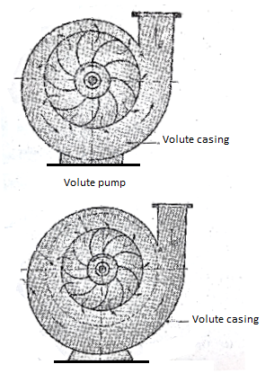
- Volute pump or constant velocity pump
Fig. Shows a centrifugal pump with a volute or collecting passage round the impeller of gradually increasing area from cut water at A to delivery pipe at B.
The cross-section is so designed to give constant velocity in the volute of spiral shape. For this reason, it is also called as constant velocity volute.
In such a volute casing the loss of energy is considerably reduce compared to a circular casing if employed However, the conversion of kinetic energy into pressure energy is not possible. Due to this the efficiency of pump only increases slightly.
b. Vortex or variable velocity volute pump
As improvement of the design of volute pump is shown in Fig. This pump has relatively larger overall diameter. Compared to pump shown in Fig. In order to provide an annular space between the impeller and volute passage
In this annular space called vortex chamber, there is a free vortex in which the velocity of flow of liquid falls as it passes into this chamber from impeller outlet to entry of volute passage. (Since in a free vortex, the velocity of whirl is proportional to radial distance). Due to decrease in velocity the pressure increases racially from centre outwards
The drawback of this arrangement is that to get an efficient chamber the dimensions become excessive and the pump becomes bulky and expensive.
The volute pumps and vortex volute pumps are single stage pumps with horizontal shaft
c. Diffuser or turbine pump
Fig. Shows a diffuser or turbine pump which is similar to vortex volute pomp, but a diffuser ring with guide vanes is fixed in annular space.
Function of guide vanes is to guide the liquid leaving the impeller in streamlined diverging passages into the volute chamber from where it flows to the delivery pipe.
In case of multistage pumps, the liquid from volute chamber flows into the eye of impeller of the next stage pump and the final stage volute discharges into delivery pipe
This pump with diffuser ring becomes in fact a reversed reaction turbine and is therefore commonly known as a turbine pump
The guide vane passages so formed have an increasing cross-sectional area which reduces the velocity of flow hence, the partial kinetic energy of the liquid is converted into pressure energy Further conversion of kinematic energy into pressure energy takes place in the volte chamber of increasing cross sectional area
3. Based on liquid handled (Types of impellers)
Depending on the type and viscosity of liquid to be handled, a pump uses three types of impellers, accordingly pumps are classified as follows
(a) Shrouded or enclosed impeller
(b) Semi-open impeller
(c) Open impeller
(a) Shrouded or enclosed impellers
In this type of impellers, the vanes of impeller are cast between two circular discs or plates (shrouded) as shown in Fig. The plates on entry side is called crown plate and the plate on hack or shaft side is called base plate.
This arrangement provides better guidance for liquid to flow and prevents leaking of liquid from blade tips from dirt
One passage to another passage with high efficiency These types of impeller pumps are mostly used for clear war or for other liquids of low viscosity free from dirt
(b) Semi-open impellers
This impeller has a plate only on back side called based plate as shown in fig.
Such an arrangement helps in dealing liquids mixed with fibrous materials. Therefore, these types of impellers can be used in sewage installation sugar and pulp industry etc. with small amount of debris
(c) Open impellers
These types of impellers do not have any cover plate on either side of the vanes. Therefore, these types of impeller are open from both sides as shown in Fig.
Open to deal with liquid which may contain suspended solid a such as sand, grit, clay etc. since these pumps do not clog Centrifugal Pump
4. Based on relative direction of flow through impeller
Based on relative direction of flow through impeller and on the direction of flow of liquid the impeller the pumps are classified as
(a) Radial flow
(b) Mixed flow
(c) Axial flow
- Radial flow pumps
Most of the centrifugal pumps are radial flow type in which the liquid flows in the impeller in radial direction only as shown in Fig.
In radial type of impellers, the liquids enter at the centre of impeller axially and then it flows racially over impeller blades up to outer periphery. In this the pressure head is developed doe to centrifugal force impressed upon the
b. Mixed flow pumps
It is the modification of radial flow impeller in which the flow is the combination of axial and radial flow and the impeller resembles the propeller of a ship. These are also called as screw pumper due to their resemblance to shape of a screw
The mixed flow impellers have large discharge rates of liquid compared to radial flow impellers at low heads
Therefore, these types of pumps are suitable for irrigation applications.
c. Axial Glow pumps
In axial flow pumps the direction of flow of liquid through its impeller is in the axial direction only from inlet to exit.
These pumps are designed for very large discharge rates at low heads, hence these are ideally suited for irrigation. The pressure head developed in axial flow pump is not due to centrifugal action, rather it is due to flow of liquid on made of aerial section similar to generation of lift by the wings of an aero plane
These pumps have adjustable blades similar to runner blades of a Kaplan turbine.
5. Based on number of entrances to impeller
The centrifugal pumps based on number of entrances to the impeller can be classified as follows
- Single entry pump
In this pump the legal enters only from one side into the impeller from suction pipe as shown in Fig. These are also called as single auction pump
b. Double entry or double suction pump
In these pumps entry to impeller is from both sides of impeller. In such pumps the axial thrust is suitable for large discharge rates is negligible
Key takeaways:
- In axial flow pumps the direction of flow of liquid through its impeller is in the axial direction only from inlet to exit.
- These pumps are designed for very large discharge rates at low heads, hence these are ideally suited for irrigation
- The pressure head developed in axial flow pump is not due to centrifugal action, rather it is due to flow of liquid on made of aerial section similar to generation of lift by the wings of an aero plane
A pump is a power absorbing device in which the work is done by impeller on water
The inlet and outlet velocity diagrams as shown in Fig. Can be drawn in similar way as drawn for an inward f reaction turbine Notations used are same.
In pumps, the water enters the impeller at its centre and leaves at its outer periphery.
Following assumptions are made
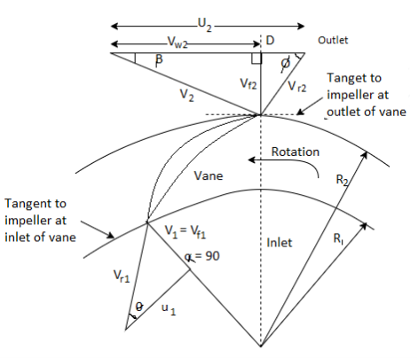
(1) Liquid enters the impeller vane racially for best efficiency i.e., α = 90, therefore, V₁= Vf1 and velocity of whirl, Vw1., = 0.
(2) Liquid enters and leaves the vane without shock
(3) The velocity distribution in passages between vanes is uniform. The velocity distribution in D₁ Diameter of impeller at inlet = 2 x Radius R1
D2 Diameter of impeller at outlet = 2 x Radius of R2
N=Speed of impeller in rpm.
The tangential blade velocity at inlet, u, and at outlet, u2 can be written as


V= absolute velocity
Vr= relative velocity
Vf= velocity of flow
Vw= velocity of whirl
Suffix 1 and suffix 2 represent the velocities at inlet and outlet respectively.
α= angle made by absolute velocity V1 at inlet
 = inlet angle of vane
 = outlet angle of vane
 = discharge angle of absolute velocity at outlet
Work done (W.D.) by impeller on water per N weight of liquid per second is given as

Above equation is known as Euler’s momentum equation for centrifugal pump
But Vw1 = 0 since entry is radial

In case working liquid is water and the weight of water is W then the work done on water per second becomes

Where,
Weight of water/s = 
Discharge rate= Area X velocity of flow

Where, B1 and B2 is width of impeller at inlet and outlet resp.
Key takeaways:
1. Liquid enters the impeller vane racially for best efficiency i.e., α = 90, therefore, V₁= Vf1 and velocity of whirl, Vw1., = 0.
2. Liquid enters and leaves the vane without shock
3. The velocity distribution in passages between vanes is uniform
Various heads connected with centrifugal pump installation
Pressure head, H in meter of fluid column is given by the equation,

V = Velocity of liquid in suction pipe. m/s.
Vd= Velocity of liquid in delivery pipe. m/s
Hfs = Loss of head due to friction in suction pipe, m;
Hfd=Loss of head due to friction in delivery pipe, m Let
Definitions connected with various types of head are as follows
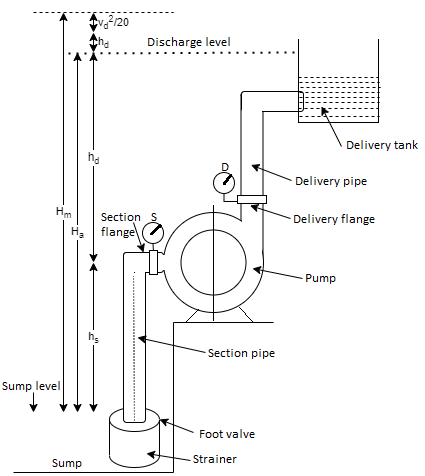
- Suction lift, hs: It represents the vertical distance between the top surface level of sump and the centre of impeller
2. Delivery lift hd: 1 It represents the vertical distance between the centre of impeller and the discharge level in delivery tank.
3. Static head, Hs: It is the sum of suction lift, h, and delivery lift, h, i.e., it represents the vertical distance between the top surface level of sump to discharge level in delivery tank. Hence static head, H, Suction lift, hs, + Delivery lift, hd.
4. Gross head, Hg: The pump is required to work against the static head and the other losses like friction losses in piper and head corresponding to kinetic energy due to suction and delivery velocity of liquid. The total head against which the pump has to work is called the gross bead, H
Gross head, H, Static head, H, + Friction losses in suction and delivery pipe (h+h) + Velocity heads 
5. Manometric bead, Hm: The manometric head is defined as the minimum amount of head against which the pump has to work to deliver the required discharge. It is required to operate against the following heads
(a) To develop the static head, H
(b) To overcome the friction losses in suction and delivery pipes and the friction losses in pipes fittings valve, bends
(c) The velocity bead at discharge to maintain the delivery of liquid.
A Manometric head, Hm = Static head. Hs, + Friction losses, (hfs +hfd) + Velocity head at discharge.
Note that the manometric head. Hm does not include the friction loss head in impeller and casing of the pump,
Usually, the discharge velocity head is small compared to static head and friction head therefore, this head is mostly neglected etc.
6. Relation between Manometer Head and Work done by impeller on Liquid
The manometric head H is also equal to the difference of head imparted by impeller to liquid and the loss of head impeller and casing Hence,

Where,
Hf1= head loss in impeller,
Hf2 = head loss in casing
7. Virtual Head, H
The virtual head represents the total head through which the liquid can be lifted when all friction losses in pipes, impeller and casing are neglected. Therefore, head loss in casing
8. Manometric Head in terms of Suction and Delivery Pressure Measured by Pressure Gauge
Consider that the suction gauge (S) and delivery pressure gauge (D) are installed at suction flange and delivery flange as
Using Bernoulli's equation we can write,

Where, w= Density of liquid in N/m-p-g
In case the suction and delivery pipes are of equal diameters,
Then Vs = Vd
Equation reduces to: 
Key takeaways:
- Suction lift, hs: It represents the vertical distance between the top surface level of sump and the centre of impeller
- Delivery lift hd: 1 It represents the vertical distance between the centre of impeller and the discharge level in delivery tank.
- Static head, Hs: It is the sum of suction lift, h, and delivery lift, h, i.e., it represents the vertical distance between the top surface level of sump to discharge level in delivery tank. Hence static head,
Losses in Pumps:
Various losses which occur during the operation of a centrifugal pump are as follows:

1. Hydraulic losses
Explain the following term related to a centrifugal pump Hydraulic loss. These losses represent the loss of head in pumping installation which are
Losses in pump
(a) Loss of head due to friction in impeller
(b) Loss of head due to shock and eddy's from inlet to exit of impeller
(c) Loss of head in guide vanes due to diffusion and in casing.
Other hydraulic losses
(a) Friction loss in suction and delivery pipes.
(b) Loss of head in bends, fittings, valves etc.
2. Mechanical losses:
Due to disc friction in impeller, friction in bearings and other mechanical parts of the pump
3. Leakage loss
The difference between theoretical and actual discharge is called as the slip. It affects the manometric efficiency and power input to the pump.
A certain ant of energy is loss due liquid which is finally lost in eddies. The liquids leaked through the gland stuffing box etc.
Efficiencies of a Centrifugal Pump
Various efficiencies related to centrifugal pump are
1. Mechanical efficiency
The ratio of power available at the impeller i.e., power delivered by impeller to liquid to the power input at the shaft (motor power or shaft power) is known as mechanical efficiency
Therefore

But power available at impeller is given as


2. Manometric efficiency,
It is defined as the ratio of manometric head Hm developed by the pump to the head imparted by the impeller to liquid
Mathematically

3. Volumetric efficiency
It is ratio of actual liquid discharged from the pump in m^3/s to the theoretical liquid passing through the impeller in m^3/s mathematically

4. Overall efficiency
It is defined as the ratio of power output of the pump called water power to the shaft power
Thus

Key takeaways:
(a) Loss of head due to friction in impeller
(b) Loss of head due to shock and eddy's from inlet to exit of impeller
(c) Loss of head in guide vanes due to diffusion and in casing.
When pump is started, it will not deliver any liquid until the pressure difference in impeller is large enough to overcome the manometric head.
The pressure head developed is due to centrifugal head caused by the centrifugal force impressed on rotating liquid.
But centrifugal head = (u2^2 –u2^2)/2g
The flow will only commence when the centrifugal head exceeds the manometric head, H, therefore,


For minimum speed

Equation gives the minimum speed required for pump to start discharging the liquid.
Key takeaways:
- When pump is started, it will not deliver any liquid until the pressure difference in impeller is large enough to overcome the manometric head.
- Pressure head developed is due to centrifugal head caused by the centrifugal force impressed on rotating liquid.
Pumps are typically grouped into huge categories—tremendous displacement pumps and dynamic (centrifugal) pumps.
Positive displacement pumps use a mechanical approach to differ the dimensions of (or move) the fluid chamber to motive the fluid to waft. On the alternative hand, centrifugal pumps impart momentum to the fluid via way of means of rotating impellers which might be immersed within side the fluid.
The momentum produces a growth in stress or waft on the pump outlet. Positive displacement pumps have a consistent torque characteristic, while centrifugal pumps display variable torque characteristics. This article will talk handiest centrifugal pumps. A centrifugal pump converts driving force strength to kinetic strength in a liquid via way of means of accelerating the fluid to the outer rim of an impeller. The quantity of strength given to the liquid corresponds to the rate at the threshold or vane tip of the impeller. The quicker the impeller revolves or the larger the impeller, then the better the rate of the liquid on the vane tip and the more the strength imparted to the liquid.
Head—Resistance to Flow in Newtonian (true) fluids (non-viscous liquids, which include water or gasoline), the time period head is the dimension of the kinetic strength that a centrifugal pump creates. Imagine a pipe taking pictures a jet of water instantly into the air. The top that the water reaches are the head. Head measures the peak of a liquid column, which the pump ought to create as a result of the kinetic strength the centrifugal pump offers to the liquid.
The foremost motive for the usage of head as opposed to strain to degree a centrifugal pump’s strength is that the strain from a pump will extrude if the unique gravity (weight) of the liquid changes, however the head will now no longer extrude.
End customers can constantly describe a pump’s overall performance on any Newtonian fluid, whether or not it's far heavy (sulfuric acid) or light (gasoline), through the usage of head. Head is associated with the speed that the liquid profits whilst going thru the pump. All the kinds of strength worried in a liquid go with the drift machine may be expressed in phrases of toes of liquid. The overall of those heads determines the whole machine head or the paintings that a pump should carry out within side the machine. The distinctive varieties of head—friction, speed and strain are described on this section.
Friction Head (hf): Friction head is the top required to triumph over the resistance to glide within side the pipe and fittings. It relies upon at the size, situation and sort of pipe; the wide variety and sort of pipe fittings; glide rate; and nature of the liquid.
Velocity Head (hv): Velocity head is the power of a liquid due to its movement at a few pace (V). It is the equal head in ft via which the water might ought to fall to collect the identical pace or, in different words, the top essential to boost up the water. Velocity head may be calculated

Key takeaways:
- Pumps are typically grouped into huge categories—tremendous displacement pumps and dynamic (centrifugal) pumps.
- Positive displacement pumps use a mechanical approach to differ the dimensions of (or move) the fluid chamber to motive the fluid to waft.
- On the alternative hand, centrifugal pumps impart momentum to the fluid via way of means of rotating impellers which might be immersed within side the fluid.
Minimum Diameter of Impeller and pipes D
Usually external diameter, D, = 2 x internal diameter, D1, Le. D2, = 2D1,
Using the concept of minimum starting speed pump N to deliver the given head, H, we can determine the minimum diameter of impeller D, from Equation


1. Pumps in series
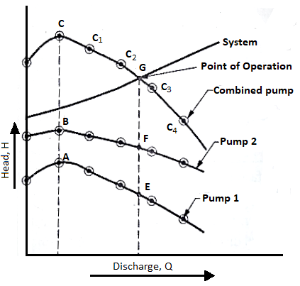
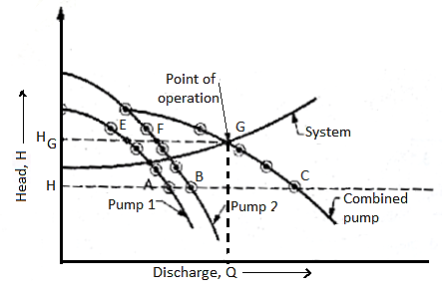
When two identical pumps in series are connected in series the total head developed by the multistage pump is the sum of head developed by each pump while the discharge remain the same equal to discharge of each pump
Therefore, the combined characteristics curves can be plotted but adding the head of each pump at constant different discharges as shown in fig.
The system character tics curves are also shown in fig. The intersection of system and combined pump characteristics curve at point G represents the point of operation
Total head developed = head developed by pump 1+ head developed by pump 2


2. Pumps in parallel
Therefore, the combined characteristics curve can be plotted by taking the locus of point of combined discharge at various constant heads as shown in fig.
The system characteristics curve is also in fig. Which intersect the combine characteristics curve at G point represents the point of operation of multistage pump in parallel
Total discharge at point G = Sum of discharge of pumps 1 and 2 head HG
Q total = QE+QF
H total = HG=HE=HF
Key takeaways:
- When two identical pumps in series are connected in series the total head developed by the multistage pump is the sum of head developed by each pump while the discharge remain the same equal to discharge of each pump
- Estimation of Maximum Permissible Suction Lift
As discussed above, the cavitation occurs when the pressure at inlet to impeller falls below the vapour pressure liquid, p. Therefore, to avoid cavitation the condition is that

Therefore, the limiting value of absolute suction pressure at inlet to impeller is p, P. On substituting this value a
Equation the maximum permissible suction lift, h, can be estimated as follows

Permissible suction lift,

Note: The vapour pressure of liquid increases with the increase in temperature.
2. Net Positive Suction Head (NPSH)
The net positive suction head (NPSH) is defined as the absolute pressure head at the inlet to the pump to force the liquid into the pump at a given temperature.
Fig. Shows how the pressure at the eye of impeller falls below the atmospheric pressure.
It is necessary that NPSH into the eye of impeller.

Therefore,

The value of NPSH is mainly affected by the temperature of liquid to be handled by the pump since hv and hfs are the function of temperature
NPSH (Required)
Required NPSH is based on the pump design and its speed and capacity. It is then tested to determine the NPSH at de pomp gives the maximum efficiency. Accordingly, the value of NPSH required is specified by the manufacturer of mp It presents the minimum value of NPSH to avoid cavitation at specified discharge and speed.
NPSH (Available)
Available NPSH of the pump is estimated after installation of pump which is based on the suction pipe diameter, liquid be handled and temperatures of operation (both the place of installation and the liquid temperature), length of suction pipe a coefficient of friction and flow rates. While estimating this NPSH, the diameter of suction pipe must be same as per acturer's design specifications.
In order to have cavitation free operation of pump the available NPSH must be greater than the required NPSH. NPSH available must be higher than NPSH required.
Key takeaways:
- The net positive suction head (NPSH) is defined as the absolute pressure head at the inlet to the pump to force the liquid into the pump at a given temperature.
- In order to have cavitation free operation of pump the available NPSH must be greater than the required NPSH. NPSH available must be higher than NPSH required.
Cavitation is defined as the phenomenon of formation of vapour bubbles in the region of flowing liquid where its pressure falls below the vapour pressure of liquid, then the liquid will vaporize and flow will no longer will be continuous.
When these vapour bubbles travel into the region of higher pressure, they suddenly collapse on the metallic surfaces and the surrounding liquid rushes to fill the cavities of vapour bubbles. The severe rush of liquid causes the development of extremely high pressures
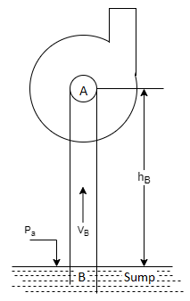
Prolonged cavitation causes erosion and putting of metals, severn vibrations and noise. Fig. Shows the suction side of pump. Consider two points A and B at inlet to eye of impeller and on the sump level respectively.
Let,
Pa = absolute atmospheric pressure.
Ps= absolute pressure at eye of impeller
Hs = suction lift
Vs = velocity in suction pipe
Hfs = friction losses in suction pipe
By Bernoulli’s theorem


Therefore, the absolute pressure at inlet to eye of impeller falls below that of atmospheric pressure
Estimation of Maximum Permissible Suction Lift (Limited by Cavitation)
As discussed above, the cavitation occurs when the pressure at inlet to impeller falls below the vapour pressure liquid, p. Therefore, to avoid cavitation the condition is that

Therefore, the limiting value of absolute suction pressure at inlet to impeller is p, P. On substituting this value a
Equation the maximum permissible suction lift, h, can be estimated as follows

Permissible suction lift,

Note: The vapour pressure of liquid increases with the increase in temperature.
Net Positive Suction Head (NPSH)
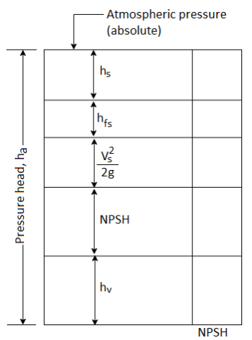
The net positive suction head (NPSH) is defined as the absolute pressure head at the inlet to the pump to force the liquid into the pump at a given temperature.
Fig. Shows how the pressure at the eye of impeller falls below the atmospheric pressure.
It is necessary that NPSH into the eye of impeller.

Therefore,

The value of NPSH is mainly affected by the temperature of liquid to be handled by the pump since hv and hfs are the function of temperature
NPSH (Required)
Required NPSH is based on the pump design and its speed and capacity. It is then tested to determine the NPSH at de pomp gives the maximum efficiency. Accordingly, the value of NPSH required is specified by the manufacturer of mp It presents the minimum value of NPSH to avoid cavitation at specified discharge and speed.
NPSH (Available)
Available NPSH of the pump is estimated after installation of pump which is based on the suction pipe diameter, liquid be handled and temperatures of operation (both the place of installation and the liquid temperature), length of suction pipe a coefficient of friction and flow rates. While estimating this NPSH, the diameter of suction pipe must be same as per acturer's design specifications.
In order to have cavitation free operation of pump the available NPSH must be greater than the required NPSH. NPSH available must be higher than NPSH required.
Thoma's Cavitation Factor
We have seen above, the cavitation may occur when the pressure of the liquid on suction side drops below the vapour pure of liquid The cavitation in a pump can be noted by the sudden drop in discharge and its efficiency along with details and the intensity of cavitation increases with the decrease in NPSH, Therefore, the cavitation imposes a limit on the discharge by the pump and its speed of rotation
Equation can be rewritten in the following form


Dividing by manometric head Hm

In the above equation V^2/2gH is called Thoma Cavitation factor

The cavitation will occur if the value of Thomas cavitation factor, is less than the critical value., at which the cavitation just begins. It implies that

Key takeaways:
- Cavitation is defined as the phenomenon of formation of vapour bubbles in the region of flowing liquid where its pressure falls below the vapour pressure of liquid, then the liquid will vaporize and flow will no longer will be continuous.
- When these vapour bubbles travel into the region of higher pressure, they suddenly collapse on the metallic surfaces and the surrounding liquid rushes to fill the cavities of vapour bubbles.
- The severe rush of liquid causes the development of extremely high pressures
A submersible pump is similar to centrifugal pump having design similar to diffuser or turbine pump discussed earlier with radial or mixed flow impellers. It helps in making their size compact. These are generally multistage type so as to develop high heads.
The motor and the pumps are made as one compact. Unit which is submerged in water while in operation Unit is mounted in a vertical configuration.
The pump is above the motor having a common shaft. The pump is connected to the rising main by flanges and it is suspended in it.
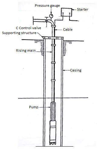
Between the pump and the motor, the suction is provided. However, there is no problem of suction since the pump is submerged. A non-return valve is provided at the delivery end.
Submersible motors are water filled, water lubricated squirrel cage type of motor. The axial thrust generated by the pump is absorbed by the thrust bearings fitted at the bottom of the motor.
Sealing is provided to prevent the well water from entering the motor and mixing with water already filled inside. (Note that the water which is filled inside the motor for cooling and lubrication is different from the well water).
Submersible pumps are efficient, maintenance free, silent and smooth running for considerable period of time. It should only be used for pumping of clean and cold water which is non-corrosive and non-abrasive to pump material.
It is used for irrigation in drinking water supply installation, pressure boosting air conditioning systems, industrial plants, cooling water systems, fountains, sea water desalination etc.
Key takeaways:
- A submersible pump is similar to centrifugal pump having design similar to diffuser or turbine pump discussed earlier with radial or mixed flow impellers.
- It helps in making their size compact. These are generally multistage type so as to develop high heads.
- The motor and the pumps are made as one compact unit which is submerged in water while in operation Unit is mounted in a vertical configuration.
A centrifugal pump designed to develop certain manometric head and discharge at constant speed since the pump set driven by A.C. Motors.
In certain cases, the pumps may be driven by an I.C engine at variable speed or the pump in actual practices may needed to develop a certain head or discharge. Under this actual condition the behavior of the pump will be different than expected. Therefore, various tests on the pump under variable conditions are conducted in order to predict the behaviour and Hence of the pump. The test results are then plotted on a graph under different flow rates, head and speed. The curves thus obtained are known as characteristic curves for the pump.
Types of Performance Characteristic Curves
The performance characteristic curves are broadly divided into following four categories
1. Main characteristic curves
2. Operating characteristic curves
3. Iso-efficiency or Muschel curves
4. Constant head and constant discharge curves
a. Main Characteristic Curves

Main characteristic curves are obtained by test run at constant speed and the discharge Ar each discharge, the mano metre head H, and input power P are measured and the overall efficiency n, is calculate is varied by means of delivery
Test curves are planed between H Vs Q.PVs Q and r Vs Q as shown in Fig. For that constant speed. The test run is repeated by running the pump at another constant speed. A family of curves will be obtained at various constant speeds N. N, as shown in Fig.
b. Operating Characteristic Curves
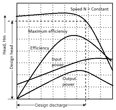
The pumps are designed for maximum, efficiency at a given speed called designed speed.
Therefore, the pumps are test run at designed speed as provided by the manufacturer of the pump
Design discharge characteristic curve and the head and power input are measured. The overall efficiency of the pump is calculated.
The performance curve thus obtained at design speed are called characteristic operating.
c. Iso-efficiency or Maschel Curves
Iso-efficiency Le constant efficiency curves are useful in predicting the performance on entire operations and its bet performance.
These characteristic curves can be drawn with the help of n, Vs Q and H, Vs Q curves shown Fig. Respectively. The method is as follows
(1) Draw a borontal line on n, Vs Q curve. It represents the constant efficiency line.
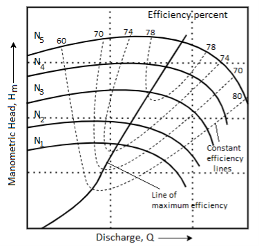
(2) The points at which the constant efficiency line cuts the constant speed lines, the discharges (3) At a given discharge and speed, the Hm is noted from H Vs Q graph are noted
(4) These values of H and Q at constant efficiency and speed are projected on a graph of H, Vs Q
(5) The points corresponding to same overall efficiency are then joined with a smooth curve. These curves represent the iso-efficiency curves. These iso-efficiency curves help to locate the regions where the pump would operate at maximum efficiency.
d. Constant Head and Constant Discharge Curves
Often a centrifugal pump is draw required to operate variable speed than the signed speed. Therefore, it is necessary to the performance curves of a pump at unable speed so that these curves can be used to predict the performance.
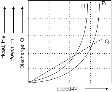
The procedure is as follows:
The delivery valve opening is fixed and kept constant during the test on jump. Then it is operated at variable speed. For each speed the manometric head H. Discharge Q and power input P, are measured.
The graphs H Vs N. P, Vs N and Q Vs N can be drawn as shown in fig
Specific Speed
Suction specific speed is another parameter used in pumps to indicate whether the cavitation will occur. It is defined as the speed of geometrically similar model pump which will operate with similar degree of cavitation.
Specific speed of the pump is given as

Therefore, replacing H by NPSH for similar degree of cavitation, the suction specific speed, can be written as:
Suction specific speed,


Model testing:
Test set up fir conduct of tests on centrifugal pump in a laboratory:
- It consists of a water storage tank of suitable capacity on which the pump along with motor and variable speed arrangement is fixed. The suction of the pump is connected through the suction line and the strainer cum foot valve arrangement to the storage tank. The pump delivery is connected through a flow control valve to the measuring tank
- On the suction line, a vacuum gauge is fitted and a pressure gauge is fixed on the delivery line. Arrangement for priming the pump is provided using a priming cock and funnel on to the delivery line
- Measuring tank consists of level indicator glass tube and the scale to measure discharge. Below the measuring tank, the drain value is fitted which allows to drain the water from measuring tank to storage tank
- The motor is connected through an energy motor which is fixed on the control panel. The motor speed is measured by the digital pickup indicator located on the control panel. The delivery head is measured by pressure gauge and the vacuum at pump suction is measured by vacuum gauge.
- The pump is tested at constant speed by varying the discharge rates controlled by the flow control valve. The power input is named by energy meter. The pump efficiency is calculated. Various graphs are plotted for power, head
- Experiments are repeated at variable speed by keeping the constant valve opening. Head, discharge and power input are and various performance curves at plotted.
Key takeaways:
- The motor is connected through an energy motor which is fixed on the control panel.
- The motor speed is measured by the digital pickup indicator located on the control panel.
- The delivery head is measured by pressure gauge and the vacuum at pump suction is measured by vacuum gauge.
- The pump is tested at constant speed by varying the discharge rates controlled by the flow control valve. The power input is named by energy meter. The pump efficiency is calculated. Various graphs are plotted for power, head
Case study
- Submersible pump
A submersible pump is similar to centrifugal pump having design similar to diffuser or turbine pump discussed earlier with radial or mixed flow impellers. It helps in making their size compact. These are generally multistage type so as to develop high heads.
The motor and the pumps are made as one compact. Unit which is submerged in water while in operation Unit is mounted in a vertical configuration.
The pump is above the motor having a common shaft. The pump is connected to the rising main by flanges and it is suspended in it.
Between the pump and the motor, the suction is provided. However, there is no problem of suction since the pump is submerged. A non-return valve is provided at the delivery end.
Submersible motors are water filled, water lubricated squirrel cage type of motor. The axial thrust generated by the pump is absorbed by the thrust bearings fitted at the bottom of the motor.
Sealing is provided to prevent the well water from entering the motor and mixing with water already filled inside. (Note that the water which is filled inside the motor for cooling and lubrication is different from the well water).
Submersible pumps are efficient, maintenance free, silent and smooth running for considerable period of time. It should only be used for pumping of clean and cold water which is non-corrosive and non-abrasive to pump material.
It is used for irrigation in drinking water supply installation, pressure boosting air conditioning systems, industrial plants, cooling water systems, fountains, sea water desalination etc.
2. Centrifugal pump
A centrifugal pump has the following main components as:
1. Impeller
2. Suction pipe with strainer and foot valve
2. Casing
4. Delivery pipe
Impeller
An impeller is a wheel or rotor having a series of backward curved vanes or blades.
The impeller is mounted on a shaft which is usually coupled to a motor. The motor provides the required energy to rotate the impeller.
Casing
The impeller is enclosed in a watertight casing with delivery pipe on one side and with an arrangement on suction side called eve of impeller as shown in Fig.
Casing has to perform two functions. Firstly, it guides the water from entry to exit of impeller Secondly, the casing is so designed that it helps in partly converting the kinetic energy of the liquid into pressure energy.
Suction pipe with strainer and foot valve
The pipe which connects the sump to the eye of impeller is called suction pipe. The sump carries the liquid to be lifted by the pump.
The suction pipe at its inlet is provided with a strainer and a foot valve. The function of strainer is to prevent the entry of any debris into the pump. The foot valve is a non-return valve which allows the flow of water only in upward direction.
Therefore, this valve does not allow the liquid to drain out from suction pipe.
Delivery pipe
The pipe which connects the outlet of pump up to point it delivers the liquid to require height is called delivery pipe. A valve is provided in the delivery pipe near the outlet of the pump called delivery valve. It is a sluice open. Its function is to regulate the supply of liquid from the pump to delivery pipe.
Casing
The impeller is enclosed in a watertight casing with delivery pipe on one side
Working of Centrifugal Pump:
Centrifugal pump works on the principle that when a certain mass of liquid is made to rotate along the impeller from the central axis of rotation, it impresses a centrifugal heat. It causes the water to move racially outwards at higher velocity and causes the water to rise to a higher level. The motion of water is restricted by casing of pump, it results into pressure build up. In addition, the change in angular momentum of liquid during its flow results into increase in pressure head.
The steps involved in operation of centrifugal pump are as follows:
1. The delivery valve is closed.
2. The priming of the pump is carried out Priming involves the filling the liquid in suction pipe and casing up to the level of delivery valve so that no air pockets are left in the system If any air or gas pockets are left in this portion of pump, it may result into no delivery of liquid by the pump.
3. The pump shaft and impeller are now rotated with the help of an external source of power like a motor or any other prime mover,
4. The rotation of impeller inside a casing full of liquid produces a forced vortex which is responsible in imparting the centrifugal head to the lignite creates a vacuum at the eye of impeller and causes liquid to raise into suction pipe from the sump
4. The speed of impeller should be sufficient to produce the centrifugal head such that it can initiate discharge from delivery pipe
5. Now the delivery valve is opened and the liquid is lifted and discharged through the delivery pipe due to its high pressure
Thus, the liquid is continuously sucked from the sump to impeller eye and it is delivered from the casing of pap through the delivery pipe.
References:
- Engineering Fluid Mechanics, Garde and Mirajgaonkar, Scitech
- A Text Book on Fluid Mechanics and Hydraulic Machines, Sukumar Pati, McGraw Hill,
New Delhi
3. A Text Book of Fluid Mechanics and Hydraulic Machines, R K Bansal, Laxmi
Publications Pvt. Ltd., New Delhi
4. Fluid Mechanics, Fundamentals and Applications, Yunus A Cengel and John Cimbala, McGraw Hill International, New Delhi
5. Fluid Mechanics by Frank M White, McGraw Hill
6. Fluid Mechanics by Streeter, Wylie and Bedford, McGraw Hill International, New Delhi